

Abstract
This paper describes and characterizes a novel microfabricated neuronal culture device. This device combines microfabrication, microfluidic, and surface micropatterning techniques to create a multicompartment neuronal culturing device that can be used in a number of neuroscience research applications. The device is fabricated in poly(dimethylsiloxane), PDMS, using soft lithography techniques. The PDMS device is placed on a tissue culture dish (polystyrene) or glass substrate, forming two compartments with volumes of less than 2 μL each. These two compartments are separated by a physical barrier in which a number of micron-size grooves are embedded to allow growth of neurites across the compartments while maintaining fluidic isolation. Cells are plated into the somal (cell body) compartment, and after 3–4 days, neurites extend into the neuritic compartment via the grooves. Viability of the neurons in the devices is between 50 and 70% after 7 days in culture; this is slightly lower than but comparable to values for a control grown on tissue culture dishes. Healthy neuron morphology is evident in both the devices and controls. We demonstrate the ability to use hydrostatic pressure to isolate insults to one compartment and, thus, expose localized areas of neurons to insults applied in soluble form. Due to the high resistance of the microgrooves for fluid transport, insults are contained in the neuritic compartment without appreciable leakage into the somal compartment for over 15 h. Finally, we demonstrate the use of polylysine patterning in combination with the microfabricated device to facilitate identification and visualization of neurons. The ability to direct sites of neuronal attachment and orientation of neurite outgrowth by micropatterning techniques, combined with fluidically isolated compartments within the culture area, offers significant advantages over standard open culture methods and other conventional methods for manipulating distinct neuronal microenvironments.
I. Introduction
A multicompartment culturing method for neuritic isolation was first described by Campenot for primary cultures of sympathetic neurons.1,2 In this method, a tissue culture dish is coated with collagen and parallel lines, spaced 200 μm apart, are scratched along the surface of the dish. A three-compartment Teflon piece is sealed to a tissue culture dish with silicone grease, and neurons are plated in the small central chamber of the Teflon piece. Neurites grow outward into the two other compartments on either side, aligning parallel to the scratches.1 Variations of the Campenot chamber have been used in studies of various types of long projection neurons. However, to use cortical and hippocampal neuronal cultures, it was necessary to optimize neuron outgrowth and redesign the chamber to allow neurites to enter the outer compartment after only modest periods of outgrowth. Ivins et al. developed such chambers with a relatively short barrier distance (150 μm versus 300 μm in the classic Campenot chamber).3 These chambers used a glass coverslip fixed to hemisected Teflon tubing using Sylgard 184 (Dow Corning, Corning, NY). A small amount of silicone vacuum grease (Dow Corning) was applied to the bottom of the coverslip using a dissecting microscope, and the whole apparatus was placed on the tissue culture dish. Neurites extended through the vacuum grease barrier between the polystyrene and the coverslip, if the vacuum grease barrier was sufficiently thin. The process of making these chambers was time-consuming and the percentage of useful devices was less than 30%. In addition, the chambers were not compatible with live cell imaging; thus, the effects of insults were observed only after the chambers were removed and the cells were fixed.
In this paper, we describe a new type of microfabricated neuronal device. This device can be used in a number of neuroscience applications, including Alzheimer's disease (AD) research where the ability to expose insults locally to portions of neurons is desired. The benefits of microfabrication include a reduction in reagent usage, batch processing ability, and reproducibility. In addition, we demonstrate the ability to micropattern the substrate of the device in order to align the neurites. The device is created using soft lithography techniques and has two separate compartments connected by micron-size grooves at the bottom of a 150 μm wide barrier. Within 4 days after embryonic neurons are plated in one compartment, neurites are visible through the grooves and into the adjacent compartment. The small grooves connecting the two chambers have enough resistance that a hydrostatic pressure difference between the two compartments results in the ability to contain and isolate a biomolecular insult (e.g., β-amyloid, MW = 3–4 kD) in the lesser volume compartment for many hours. Compatibility of the device with neuronal culture and characterization of the device for localized insult application were investigated.
II. Experimental Section
Fabrication of Neuronal Devices
The neuron culture device was fabricated in poly(dimethylsiloxane) (PDMS) using rapid prototyping and soft lithography following published procedures.4,5 The master for the device was fabricated by patterning two layers of photoresist (Figure 1). A 20 000 dpi high-resolution printer (CAD/Art Services, San Diego, CA) was used to generate the first transparency mask from a CAD file in order to create the microchannels (10 μm wide, spaced 50 μm apart). SU-8 5 (Microchem, Newton, MA) photoresist was spun on an air-plasma-cleaned silicon wafer at a rate of 4000 rpm for 60 s to obtain an approximate thickness of 3 μm. The transparency mask was used to pattern the SU-8 5 photoresist. SU-8 50 was used as a second layer and spun at1000 rpm for 60 s. The second mask was used to create the chamber areas; this mask was printed at 5080 dpi with a resolution of approximately 35 μm and aligned to the first pattern. After developing, the wafer was placed in a clean Petri dish and was treated with (tridecafluoro-1,1,2,2-tetrahydrooctyl) trichlorosilane to facilitate removal of the PDMS from the master mold. PDMS was made using a 10:1 ratio of prepolymer and catalyst. The Petri dish containing the wafer was then placed in a dry oven for 1 h at 70 °C. Ethanol was used to sterilize the devices.
Figure 1.

Schematic of the fabrication process for the neuron chamber. The top piece of the chamber is fabricated in PDMS by molding against a master that has a two-level photoresist pattern. Steps A and B show the formation of microgrooves (3 μm high and 10 μm wide) in the master using a thin photoresist layer. The size of the grooves was designed to limit the neurons in the somal chamber while allowing the growing neuritic processes to cross from one chamber to another. Steps C and D show the fabrication step for main compartments for soma and neurite chambers. Two chambers, separated by a barrier, form fluidically isolated areas that each hold less than 2 μL of fluid (100 μm high, 1500 μm wide, and 8 mm long). The top part of the device is formed by replica molding PDMS against the master (step E). Releasing the PDMS and sealing it to a flat substrate completes the neuron chamber fabrication (step F).
Glass coverslips (22 mm × 30 mm, no. 1 thickness, Proper) were cleaned by sonication in an ethanol solution for 30 min and then treated in an air plasma cleaner for 10 min to remove residual materials from the surfaces. The tissue culture dishes and glass coverslips were coated with poly-L-lysine (Sigma) at 50 μg/mL in sterile H2O for 2 h at room temperature. The devices and tissue culture dishes were air-dried overnight before use.
Culture of Embryonic Rat Cortical Neurons
Primary cultures of E18 rat cortical neurons were prepared as described previously.3 Briefly, cortexes of E18 rat embryos were dissected in CMF-HBSS [calcium- and magnesium-free Hanks' balanced salt solution (HBSS) containing 1 mM pyruvate, 4.2 mM sodium bicarbonate, and 0.3% bovine serum albumin (BSA)], rinsed with CMF, and resuspended in a trypsin solution (0.125% trypsin in CMF-HBSS containing 0.5 mM EDTA) for 7 min at 37 °C or 25 min at ambient temperature. Trypsinization was stopped with Dulbecco's modified Eagle's medium (DMEM) containing 10% fetal calf serum, the tissue was centrifuged at 1000 rpm for 1 min, and the resulting cell pellet was resuspended in 2 mL of culture medium (Neurobasal medium, Gibco 21103, containing B27 supplement, Gibco 17504, GlutaMAX, Gibco 35050, and penicillin–streptomycin, Gibco 15070). Following trituration through fire-polished Pasteur pipets with the diameter maximally 50% constricted, the cell suspension was filtered through a 40 μm cell strainer, and viability was determined with trypan blue. Cells were plated with densities from 1 to 4 × 10⁶ cells/mL. For plating the controls, the cell suspension was diluted 25-fold to obtain comparable cell density per area as in the devices.
Microscopy
Phase contrast and epifluorescent images were taken using an inverted microscope Nikon TE 300, aCCDcamera, and MetaMorph (Universal Imaging, PA). DG-4 was used as our excitation light source which has an internal shutter controlled by MetaMorph in order to take time-lapse images at different excitation wavelengths. We used a Prior motorized stage to take images at multiple locations throughout the samples.
Substrate Patterning
We used two methods. First, micromolding in capillaries (MIMIC)6,7 was used to selectively adsorb and pattern poly-L-lysine on the surface of tissue culture dishes. The PDMS elastomeric mold, having 25 μm lines and spaces with a depth of 50 μm, was cast from patterned silicon wafers generated with SU-8 50 by using photolithography. The degassed 10:1 mixture of elastomer and curing agent was poured over a master pattern and cured at 70 °C for 1 h. The PDMS mold was sterilized with ethanol and allowed to dry for at least 1 h; a sterile tissue culture dish was used as the substrate for the mold. A drop of a 50 μg/mL solution of poly-L-lysine (PLL) in sterile deionized (DI) water was placed at an open end of the network of channels, filling the channels by capillary action. After the channels are filled, the solution was incubated for 1 h to allow adsorption onto the surface. After this step, the PDMS mold was removed and a fresh buffer solution or sterile deionized water was used to wash away the excess solution.
The second method of patterning, microcontact printing, was used to create poly-L-lysine lines on coverglass; this technique has been described previously.8 The PDMS elastomeric stamp having 25 μm lines and spaces with a depth of 10 μm was cast from patterned silicon wafers generated with SU-8 10 by using photolithography. The degassed 10:1 mixture of elastomer and curing agent was poured over a master pattern and cured at 70 °C for 1 h. The elastomer stamp was peeled away from the master pattern after cooling. The ink was prepared under ambient atmosphere using a 5 mg/mL solution of octadecyltrichlorosilane (OTS) in a hexane solvent. The patterned face of the PDMS stamp was coated with a solution of OTS by the spin-coating technique at 1500 rpm for 30 s, dried in a stream of argon for 30 s, and then placed on top of a precleaned glass surface and kept in contact with the inked stamp for 30 s. After contact printing, the OTS-patterned sample was rinsed thoroughly in isopropyl alcohol and immersed in a 50 μg/mL solution of PLL in water for 2 h. The sample was rinsed in water and dried. Micropatterns on the glass substrates were verified using fluorescence microscopy; the micropatterned surface was exposed to a solution of 10 μg/mL fluorescein isothiocyanate (FITC; Molecular Probes, Eugene, OR) in PBS (pH 7.4, 50 mM) at 37 °C for 30 min: the terminal −NH2 group reacts with the isothiocyanate group of FITC yielding FITC-conjugated PLL patterns.9 The patterned glass substrate was then washed with DI water and ethanol.
III. Results and Discussion
Design of Neuronal Devices
The neuronal culture devices were fabricated in PDMS for the following reasons: (1) PDMS is optically transparent and well suited for live cell imaging, (2) many molds can be made from the same master with reproducible results, (3) PDMS can be covalently sealed to glass using plasma bonding, and (4) a watertight seal can also be made with polystyrene or other flat substrates by conformal contact. Both glass and polystyrene tissue culture dishes can be used as substrates for the device. The neuritic and somal compartments are connected by 120 grooves, 10 μm wide, 3 μm high, and 150 μm in length. The grooves are spaced 50 μm apart to prevent the grooves from collapsing. The size of the grooves is sufficiently small that dissociated neurons during loading do not pass over to the adjoining neuritic compartment. This design simplifies the loading process and allows selective placement of neurons in one compartment. There are four holes (8 mm in diameter) in each PDMS device, two at either end of each compartment, which serve as loading inlets and cell medium reservoirs for nutrient and gas exchange. When small holes (2.3 mm diameter) were used, the devices quickly dried out after a few days. Even if cell culture medium was added frequently, there was low cell viability with these small holes due to poor exchange of nutrients, wastes, and gases such as CO2. The volume in each covered compartment (i.e., without the reservoirs) is less than 2 μL. In comparison, the combined reservoirs for each compartment can hold up to 400 μL. By having such small culture volumes, reagent amounts can be reduced from traditional culturing methods.
After approximately 3–4 days of growth, neurites from the somal compartment extend into the neuritic compartment. The rate of neurite outgrowth in our cultures was between 50 and 100 μm per day. After 7 days, or when an insult is desired, 15 μL of medium can be transferred from the neuritic compartment to the somal compartment, leaving a net volume difference of 30 μL (assuming the volumes in the two compartments have equilibrated during the past 7 days). A 5 μL solution containing the insult can then be administered to the neuritic side. When performing these operations, we are careful to add and withdraw equivalent amounts to wells on the same side in order to minimize convective flow effects.
Viability of Neurons inside the Microfabricated Device
Viability of neurons in the device is important because it demonstrates that the neurons are healthy and not adversely affected by the device microenvironment and the materials that were used in fabrication. We compared the viability of neurons inside the microfabricated device with a control (tissue culture dish) after 7 days of culture. The viability was assessed using calcein AM and ethidium homodimer live/dead stain (Molecular Probes). Results are shown in Figure 2. Viability in the device was approximately 10–20% lower than in tissue culture controls. We noticed that the viability of neurons was very sensitive to the cell density. To get accurate viability data, we used similar cell densities in the devices and controls. We used a plating density of 3 × 10⁶ cells/mL for the devices and diluted this 1:25 for the tissue culture controls which gave us an average of 1.5 × 10⁵ cells/cm2 for both devices and controls. For each experiment, three devices and one control were used. If the three devices were judged to be equivalent, live/dead staining was done on only one of the samples. Morphologically, the cells in the devices were equivalent to the controls as shown in Figure 2A,B. The slightly lower viability inside the devices may be due to increased salt concentration from evaporation and lower nutrient and gas exchange due to the smaller total volume of media. Also, an increased ratio of dead cells may get trapped in the device because of the small compartment height (100 μm).
Figure 2.
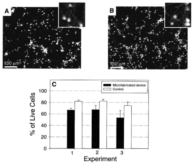
Viability of cultured primary neurons inside the microfabricated device versus tissue culture controls. (A) Fluorescence micrograph of neurons cultured for 7 days inside the microfabricated device. The PDMS top piece was sealed against a polylysine-coated tissue culture dish. Live cells were stained with a fluorescent probe, calcein AM (Molecular Probes). The box in the upper right-hand corner is a magnified section of the image showing the detailed morphology of the neurons. (B) Fluorescence micrograph of neurons cultured on a polylysine-coated tissue culture dish, without the PDMS device. Morphology typical of healthy neurons was evident in both microfabricated devices and controls. (C) Graph of cell viability inside the devices and controls after 7 days in culture (both used a polylysine-coated tissue culture dish as the substrate). The viability of cells cultured inside the microfabricated devices is slightly lower (10–20%) than that in controls, but they are generally comparable.
Targeted Insult Application, Isolation, and Characterization
For the device to be useful, we needed to determine and extend the length of time that the insult is isolated in the neuritic compartment with minimum migration/diffusion into the somal compartment. To determine the time when leakage will occur, we used fluorescent dyes to visualize infiltration of fluid from one chamber to another. Three devices were prepared by contact sealing the PDMS top to the polylysine-coated tissue culture dish. The microfabricated device was filled with PBS (∼200 μL in each somal and neuritic chamber) and placed in a water-saturated incubator for 12 h for the fluid levels to equalize. The following procedure was used to create hydrostatic pressure between the chambers: First 125 μL of PBS was added to the somal compartment, dividing the volume between the two reservoirs. Then, 100 μL of fluorescein (6 μM) in PBS was quickly added to the neuritic compartment, again, dividing the volume between the two reservoirs. The slightly higher volume on the somal side caused a slow net flow of liquid from the somal to the neuritic compartment that acts against leakage or diffusion of fluorescein from the neuritic to the somal compartment. Fluorescence images were taken every half hour for over 15 h using an exposure time of 200 ms with a FITC filter at three separate locations in each side of the somal and neuritic chamber. Intensity measurements were obtained by recording the average intensity reading of each image. In each adjoining chamber, three images were averaged for each half-hour time increment. The data were then normalized to the maximum intensity reading. Results from two devices on polystyrene dishes were averaged to plot Figure 3C. Similar results were obtained for devices on glass (data not shown).
Figure 3.
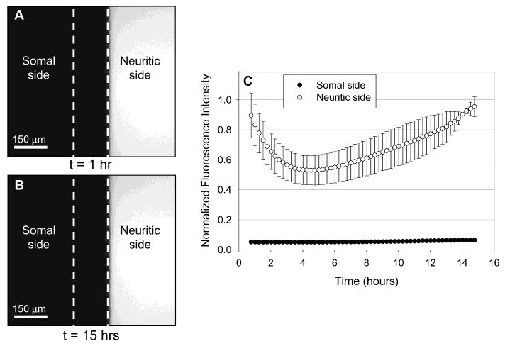
Fluorescence intensity measurements of fluorescein (400 Da) were taken in somal and neuritic compartments to characterize fluidic isolation. The left side is the somal chamber, and the right is the neuritic chamber. The dotted white line delineates the boundaries of the barrier. The microfabricated device was filled with PBS (∼200 μL in each somal and neuritic chamber) and placed in a water-saturated incubator for 12 h for the fluid levels to equalize. First, 125 μL of PBS was added to the somal compartment, dividing the volume between the two reservoirs. Then 100 μL of fluorescein (6 μM) in PBS was quickly added to the neuritic compartment, again, dividing the volume between the two reservoirs. The slightly higher volume on the somal side caused a slow net flow of liquid from the somal to the neuritic compartment that acts against leakage or diffusion of flourescein from the neuritic to the somal compartment. (A) The initial fluorescence micrograph (t = 1 h) shows that fluorescein is isolated to the neuritic compartment. (B) A fluorescence micrograph of the same region after 15 h shows that the insult is still isolated to the neuritic compartment. (C) A graph of normalized fluorescence intensity as a function of time is shown. The fluorescence intensity in the somal side is below 7% of the maximum intensity (i.e., noise level) for over 15 h, indicating that there is no leakage of fluorescein into the somal compartment during this period. The fluorescence intensity of fluorescein in the neuritic compartment decreases to 50% of the maximum due to dilution by the net flow of fluid from the somal compartment.
Figure 3C shows the fluorescence intensity of fluorescein in the somal and neuritic compartment as a function of time. The graph clearly indicates that fluorescein is isolated in the neuritic side throughout the period of measurement. The fluorescence intensity in the neuritic compartment is at background levels (below 7% of the maximum intensity) for over 15 h. The decrease in fluorescence intensity on the neuritic side is due to slow dilution from the somal side. This dilution causes a reduction in fluorescence intensity to 50% after 4 h.
To illustrate the function and effectiveness of the device, we cultured neurons in the microfabricated device allowing the neurites to extend over to the neuritic compartment. Figure 4A is a phase contrast micrograph of the neurons in the microfabricated device after 4 days in culture. Texas Red dextran (10 kDa) and calcein AM (1 kDa) were added into the neuritic compartment 1 h before taking the fluorescence micrograph, Figure 4B. A slight pressure head, corresponding to a volume differential of 20 μL of medium, was established in the somal side in order to ensure that dextran or calcein AM did not migrate from the neuritic to the somal side. Texas Red dextran was used to simulate the insult in the neuritic compartment and is clearly delineated by the barrier boundary (Figure 4B). Since calcein AM was added to the neuritic compartment, only the neurons with processes entering this compartment were illuminated. The phase contrast image shows additional neurons that were not stained with calcein AM because they did not have processes extending into the neuritic compartment; this illustrates that the neuritic compartment is fluidically isolated.
Figure 4.
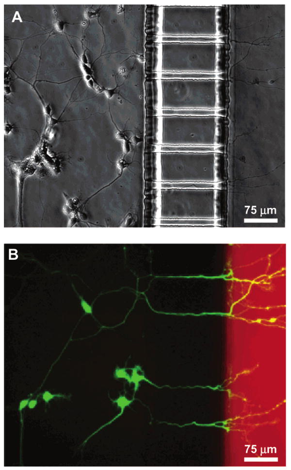
Demonstration of neuronal culture inside the microfabricated device and effectiveness of neuritic insult containment. Calcein AM and Texas Red dextran (MW = 10 kDa) were added to the neuritic chamber 1 h before taking the micrographs. A positive hydrostatic pressure difference was set up between the somal and neuritic chambers as explained in Figure 3. (A) Phase micrograph of neurons extending processes to the neuritic chamber after 4 days in culture. (B) Epifluorescence micrograph of the same region with cells stained with calcein AM (green) and isolation of Texas Red dextran (red) in the neuritic chamber. Only the live cells take up calcein and get fluorescently labeled. The micrograph clearly demonstrates selective labeling of neurons that have processes extending into the neuritic side. Texas Red dextran was added to the neuritic chamber simulating a typical insult (e.g., β-amyloid, MW = 4 kDa). A slight pressure head, an additional 20 μL of medium in the somal chamber, prevented the Texas Red dextran from migrating from the neuritic to the somal chamber. Texas Red dextran is not detectable in the somal chamber.
Substrate Micropatterning
In addition to simply isolating somas from their processes, we have also been able to pattern the growth of neurites on the substrate inside the microfabricated device. Micropatterning of the cells and their processes facilitates identification of cells and improves visualization of results. For instance, if one needs to investigate the disruption in transport of cellular cargos such as mitochondria after injury to distal neuronal processes, it is helpful to determine the direction of transport by identifying the relative position of a soma with respect to its neurites. In a random culture on a tissue culture dish, due to entangled network neurites and axons, this simple determination cannot be performed easily. If the cell body is positioned in one side of the device (on the somal side) and its processes are guided and oriented in a predetermined direction, the determination of anterograde or retrograde transport can be greatly simplified.
We used MIMIC to pattern tissue culture dishes with polylysine. MIMIC represents a technique that can pattern protein and other biological molecules.4,5,10 In MIMIC, the PDMS mold is placed on the surface of the plastic substrate and makes conformal contact with the substrate. The relief structure in the mold forms a network of empty channels. We used sterile conditions for creating our MIMIC patterns. When the PDMS mold is removed, a pattern of protein remains on the substrate. Figure 5A shows a fluorescence micrograph of FITC, which was conjugated to amine groups in polylysine.
Figure 5.
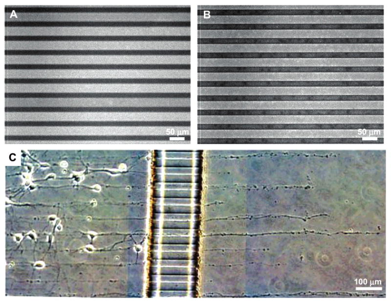
The combination of substrate micropatterning and the microfabricated device allows oriented growth of neuron processes across fluidically isolated chambers. (A) Fluorescence micrograph of polylysine patterned lines conjugated with FITC on a polystyrene tissue culture dish. MIMIC was used to pattern the lines with widths of 25 μm and a spacing of 25 μm. Bright lines indicate the region of patterned polylysine that was conjugated with FITC. (B) Fluorescence micrograph of microcontact-printed polylysine lines conjugated with FITC on a glass coverslip. Microcontact printing was used to pattern the lines with widths of 25 μm and a spacing of 25 μm. (C) Phase micrograph of neurites crossing the barrier from the somal to the neuritic chamber via the grooves while following the polylysine pattern on a tissue culture dish patterned by MIMIC (25 μm wide lines with 25 μm spacing).
Microcontact printing (μCP) is an efficient method for patterning proteins, polymers, and self-assembled monolayers (SAMs).4,5,10 Microcontact printing uses an elastomeric stamp (PDMS with a patterned relief structure on its surface) to print a variety of molecules with micron resolution. An elastomeric stamp can be made by curing PDMS against a microfabricated master.4 The surface is coated with the desired molecules (for printing proteins, the PDMS stamp will be exposed to an oxygen plasma to render its surface hydrophilic) and placed in conformal contact with the substrate. If a stamp with strips of raised regions separated by recessed regions is used, the molecules/proteins from the raised region will be transferred onto the host substrate.4,5Figure 5B shows the FITC-conjugated pattern of polylysine on glass using microcontact printing.
Figure 5C shows the growth of neurites across the barrier, via the grooves, along patterned polylysine lines. The polylysine pattern was formed on a tissue culture dish using MIMIC. Patterning of the substrates with polylysine prior to assembly with a PDMS device is simplified because the polylysine pattern can be dried and even sterilized with ethanol.
This figure illustrates that the substrate patterning methods (microcontact printing and MIMIC) can be combined with a microfabricated device to direct the sites of neuronal attachment and the orientation of neurite outgrowth. Combined with fluidically isolated compartments, this approach offers significant advantages over standard open culture methods and other conventional methods for manipulating distinct neuronal microenvironments.
IV. Conclusion
We have described a novel microfabricated neuronal culture device that allows directed growth of neurites and isolation of neurites from their cell bodies. We demonstrated the ability to use hydrostatic pressure to isolate insults to one compartment and, thus, expose localized areas of neurons to insults. Due to the high resistance of the microgrooves for fluid transport, insults are contained in the neuritic compartment without appreciable leakage into the somal compartment for over 15 h. Finally, we demonstrate the use of polylysine patterning in combination with the microfabricated device to facilitate identification and visualization of neurons. The ability to direct the sites of neuronal attachment and the orientation of neurite outgrowth by micropatterning techniques, combined with fluidically isolated compartments within the culture area, offers significant advantages over standard open culture methods and other conventional methods for manipulating distinct neuronal microenvironments.
Acknowledgments
The Institute of Brain Aging and Dementia thanks NIA (AG17765).
Footnotes
Part of the Langmuir special issue entitled The Biomolecular Interface.
References
- 1.Campenot RB. Local control of neurite development by nerve growth factor. Proc Natl Acad Sci USA. 1977;74(10):4516–4519. doi: 10.1073/pnas.74.10.4516. [DOI] [PMC free article] [PubMed] [Google Scholar]
- 2.Campenot RB. Development of sympathetic neurons in compartmentalized cultures. I. Local control of neurite growth by nerve growth factor. Dev Biol. 1982;93(1):1–12. doi: 10.1016/0012-1606(82)90232-9. [DOI] [PubMed] [Google Scholar]
- 3.Ivins KJ, Bui ETN, et al. β-Amyloid Induces Local Neurite Degeneration in Cultured Hippocampal Neurons: Evidence for Neuritic Apoptosis. Neurobiol Dis. 1998;5(5):365–378. doi: 10.1006/nbdi.1998.0228. [DOI] [PubMed] [Google Scholar]
- 4.Xia Y, Whitesides GM. Soft lithography. Angew Chem Int Ed. 1998;37:550–75. doi: 10.1002/(SICI)1521-3773(19980316)37:5<550::AID-ANIE550>3.0.CO;2-G. [DOI] [PubMed] [Google Scholar]
- 5.Whitesides GM, Ostuni E, Takayama S, Jiang X, Ingber D. Soft lithography in biology and biochemistry. Annu Rev Biomed Eng. 2001;3:335–373. doi: 10.1146/annurev.bioeng.3.1.335. [DOI] [PubMed] [Google Scholar]
- 6.Kim E, Xia Y, Whitesides GM. Polymer microstructures formed by moulding in capillaries. Nature. 1995;376:581–584. [Google Scholar]
- 7.Kim E, Whitesides GM. Imbibition and flow of wetting liquids in noncircular capillaries. J Phys Chem B. 1997;101:855–863. [Google Scholar]
- 8.Xia Y, Whitesides GM. Extending Microcontact Printing as a Microlithographic Technique. Langmuir. 1997;13:2059–2067. [Google Scholar]
- 9.Schnaible V, Przybylski M. Identification of Fluorescein-5′-Isothiocyanate-Modification Sites in Proteins by Electrospray-Ionization Mass Spectrometry. Bioconjugate Chem. 1999;10:861–866. doi: 10.1021/bc990039x. [DOI] [PubMed] [Google Scholar]
- 10.Kane RS, Takayama S, Ostuni E, Ingber D, Whitesides GM. Patterning proteins and cells using soft lithography. Biomaterials. 1999;20:2363–2376. doi: 10.1016/s0142-9612(99)00165-9. [DOI] [PubMed] [Google Scholar]