Abstract
Molecular Dynamics simulations with the CHARMM atomistic force field have been used to study monolayers of a series of linear alkylbenzene sulfonates (LAS) at the water/air interface. Both the numbers of carbon atoms in the LAS alkyl tail (1 to 11), and the position of attachment of the benzene ring on the alkyl chain have been varied. Totally 36 LAS homologues and isomers have been investigated. The surface tensions of the systems and the average tilt angles of the LAS molecules are found to be related to both the length and the degree of branching of the alkyl tails, whereas the solubility and mobility are mostly determined by the tail length.
Keywords: Computer simulation, surfactant, molecular dynamics, liquid-vacuum interface, LABS
1. Introduction
Surfactants are amphiphilic compounds which lower the surface tension of a liquid (or interfacial tension between liquids). The linear alkylbenzene sulfonate (LAS) is the world’s most important synthetic surfactant family, taking into consideration their wide applicability, cost-effectiveness, and overall consumption levels.1–5 LAS accounts for roughly 75% of synthetic detergents and 25% of the total surfactant consumption in the major industrialized countries.1 LAS has been the workhorse of the detergents industry since it was introduced in the early 1960s. The global production of LAS is over 3.0 million tons according to the statistics from European Council on Studies on LAB/LAS (ECOSOL, http://www.lasinfo.org/) and the Human and Environmental Risk Assessment project (HERA, http://www.heraproject.com/RiskAssessment.cfm).
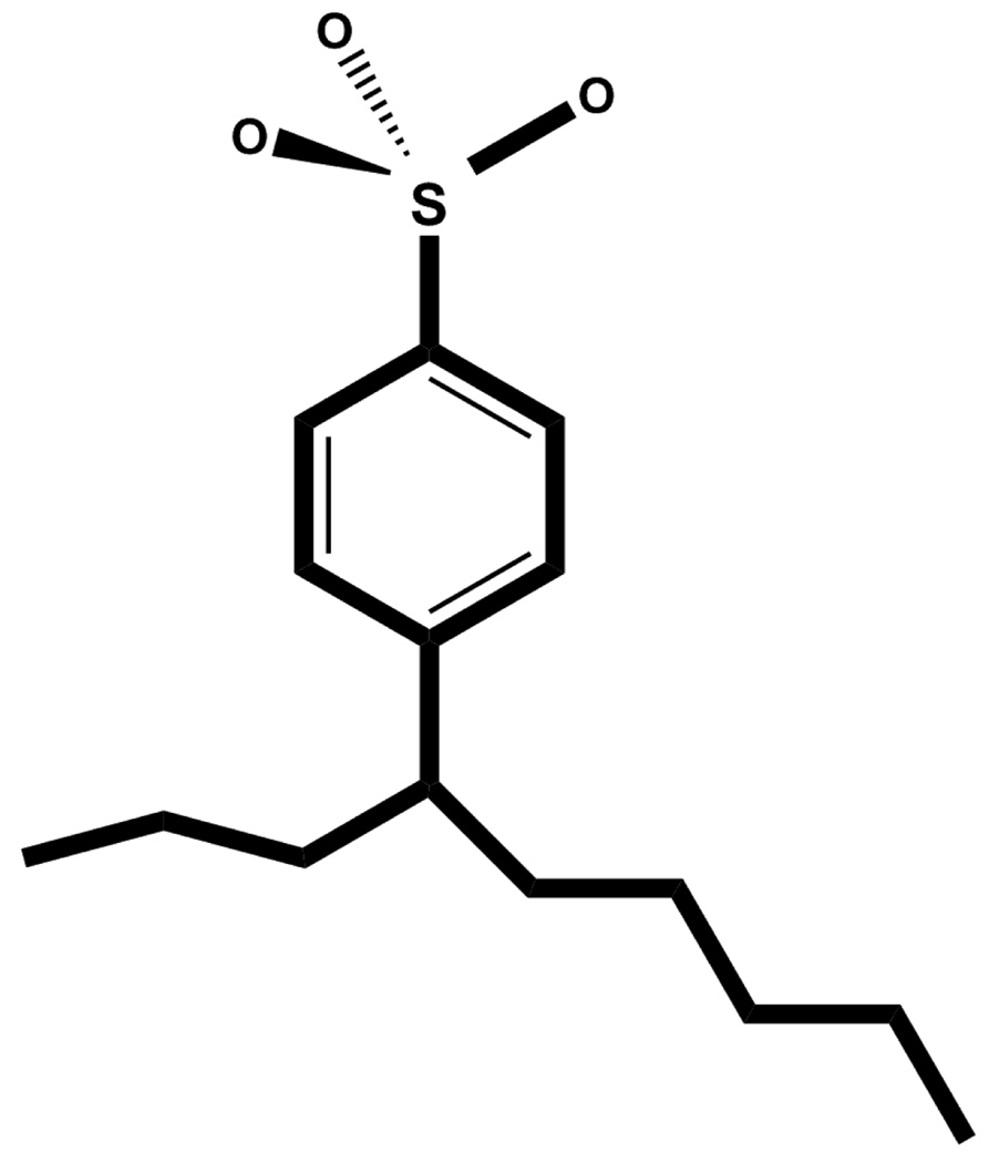
LAS is composed of a sulfonate group and a linear alkyl chain which are attached to the 1, 4 positions of a benzene ring, respectively (Figure 1).3 Commercial LAS surfactants are usually complex mixtures of homologues, i.e. different lengths of the alkyl chain, and structural isomers, i.e. different positions on the alkyl chain where the benzene ring is attached.1–3 The heterogeneous compositions improve the performance, making LAS of utility in a wide range of applications, such as detergents, cosmetics, mineral extraction, oil recovery, etc.1–5 However, this heterogeneity also makes it more difficult to elucidate the detailed mechanisms and functions of LAS members. To date, most of the research done on LAS has been performed on the mixtures, 1–7 especially in the industrial environment, and relatively few studies on pure homologues and isomers are available.8–10
Figure 1.
The structure of Φ4-C9BS, one member of the LAS family. There are 9 carbon atoms in the alkyl chain, and the benzene ring is attached to the 4th carbon.
Because of their importance in industrial processes as well as basic scientific interest, monolayers of surfactant molecules at the water/air interface have been extensively investigated during the previous decades by various experimental techniques, such as vibrational sum frequency generation,11 X-ray reflection,12 neutron reflection,13 surface tensiometry,14 Brewster angle microscopy,15 etc. However, details of the microstructures and the complex molecular interactions within surfactant systems are not easily obtained from experiments. Accordingly, the traditional “trial and error” approach is still the standard method of optimizing surfactant formula because it is difficult to predict the surfactant effect empirically.1
Computer simulations can help to correlate the microscopic details with the macroscopic properties of surfactant systems. In particular, molecular dynamics (MD) simulations have proven to be a very useful tool for the investigation of the structural and dynamical details of surfactants at a molecular level. So far, a number of MD simulation studies have been done on surfactants adsorbed at the water/air interface, but most of them focused on a few highly purified, homogeneous surfactant molecules such as sodium dodecylsulfate (SDS),16–18 alkyltrimethylammonium bromide (CTAB),18–20 or alkyl glycol ether surfactants.21–23 Very few MD simulations have been done on LAS. Tobias and co-workers24 simulated one single calcium hexadecane benzenesulfonate reverse micelle in nonpolar enviroments (CCl4, octane and vacuum) and Jang et al25 simulated sodium hexadecane benzenesulfonate at the water-decane interface. This dearth of simulation studies on LAS surfactants is surprising due to their widespread use and complexity. In this study, we applied MD simulations with the CHARMM atomistic force field on a series of homologues and isomers of the LAS family at the water/air interface. To the best of our knowledge, this is the first attempt to study and compare the LAS family members with different alkyl tails at the water/air interface systematically by atomistic MD simulations.
The rest of this article is organized as follows. In Section 2, the systems and simulation methods are described. The results obtained from the simulations are presented and discussed in Section 3. Finally, the conclusions are given in Section 4.
2. Simulation Details
A total of 36 different surfactant systems were simulated, each containing one type of LAS homologue and isomer. In this article, all surfactant molecules are referred to as Φm-CnBS, where n denotes the number of the carbon atoms in the alkyl chain (n = 1 ~ 11), and m stands for the position of the alpha carbon (Cα) in the alkyl chain where the benzene ring is attached to (m = 1 ~ 6), and BS refers to benzenesulfonate. Figure 1 shows the structure of Φ4-C9BS.
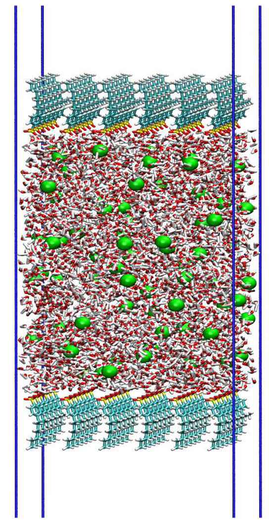
All simulated surfactant systems have similar initial configurations (Figure 2): a thick slab of bulk water with the top and bottom covered by surfactant monolayers. Initially the two monolayers are set up in the X-Y plane, with the Z axis perpendicular to the water/air interfaces. The sulfonate headgroups point into the water slab and the alkyl tails point out to the vacuum spaces which are above or below the water slab. In each system, 72 identical surfactant molecules are evenly distributed at the two water/air interfaces. The average surface area per surfactant molecule is 61 Å2. This value is within the range of experimental coverage density of C12BS isomers (43 Å2 ~ 65 Å2) at critical micelle concentration (CMC).9 To neutralize the negative charges carried by the sulfonate groups, 72 sodium ions are randomly inserted in the bulk water. The water slab contains 4679 H2O molecules, with a thickness of ~ 70 Å, which is large enough to give a distinct region of bulk solution. The total length of the Z dimension of the unit box (water slab plus surfactant monolayers plus vacuum spaces) is 300 Å. We assume that the approximate mirror symmetry combined with the large Z dimension results in negligible interactions between periodic replicas in the Z direction.
Figure 2.
A snapshot of the initial configuration of one monolayer system. The Na+ ions are drawn in green, S atoms are drawn in yellow, O atoms are drawn in read, C atoms are drawn in cyan, and H atoms are drawn in white.
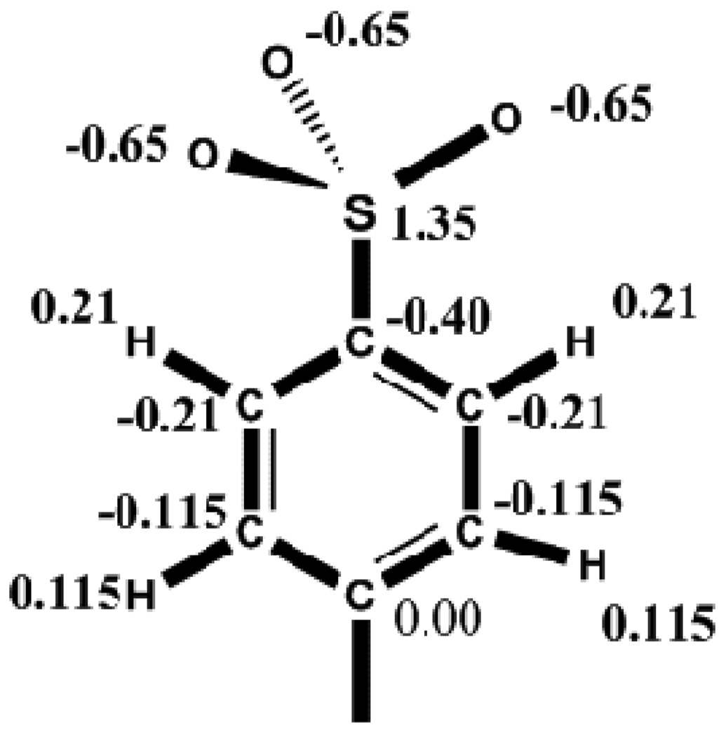
All MD simulations were performed with the program NAMD version 2.6.26 The TIP3P model27 was used for water molecules. The CHARMM force field28 was used for the alkyl tails. The charges and other parameters for the benzenesulfonate group were developed (Figure 3 and Table 1) by following the general strategy of parameterization for CHARMM force field.28,29 Periodic boundary conditions were implemented for all XYZ directions and the NVT ensemble was applied to all simulations, with the temperature T controlled at 298.0 K. The particle mesh Ewald approach30,31 was used to calculate the long-range electrostatic interactions while the van der Waals interactions were cut off at 12 Å. Covalent bonds between hydrogen atoms and heavy atoms were constrained to their equilibrium value by means of the SHAKE/RATTLE algorithm. 32,33 A time step of 1.5 fs was used. Each system was simulated for 12 ns, and the trajectories from the last 8 ns were used for data analysis.
Figure 3.
Assignment of charges on atoms in the sulfonate and benzene ring.
TABLE 1.
The parameters for the sulfonate and benzene ring of LAS homologs and isomers.
| Bonds | Kb (kCal/mol/Å2) |
B0 (Å) |
|
|---|---|---|---|
| SL-CA | 230.0 | 1.78 | |
| CTL3-CA | 230.0 | 1.49 | |
| CTL1-CA | 230.0 | 1.49 | |
| Angles | Kθ (kCal/mol/rad2) |
θ0 (degrees) |
|
| O2L-SL-CA | 85.0 | 98.0 | |
| SL-CA-CA | 10.0 | 122.3 | |
| CTL1-CA-CA | 45.8 | 122.3 | |
| CTL3-CA-CA | 45.8 | 122.3 | |
| CTL3-CTL1-CA | 51.8 | 107.5 | |
| CTL2-CTL1-CA | 51.8 | 107.5 | |
| HAL1-CTL1-CA | 49.3 | 107.5 | |
| HAL3-CTL3-CA | 49.3 | 107.5 | |
| Dihedrals | Kχ (kCal/mol) |
n | χ (degrees) |
| SL-CA-CA-HP | 4.20 | 2 | 180.0 |
| SL-CA-CA-CA | 3.10 | 2 | 180.0 |
| O2L-SL-CA-CA | 4.00 | 2 | 0.00 |
| CA-CA-CA-CTL1 | 3.10 | 2 | 180.0 |
| CA-CA-CA-CTL3 | 3.10 | 2 | 180.0 |
| CA-CA-CTL1-HAL1 | 0.00 | 6 | 0.00 |
| CA-CA-CTL3-HAL3 | 0.00 | 6 | 0.00 |
| HP-CA-CA-CTL1 | 4.20 | 2 | 180.0 |
| HP-CA-CA-CTL3 | 4.20 | 2 | 180.0 |
Note: SL and O2L stand for the S atom and O atom in the sulfonate group, respectively. CA and HP stand for the C atom and H atom in the benzene ring, respectively. CTL1, CTL3, HAL1 and HAL3 are C or H atoms in the alkyl tail according to the convention of CHARMM forcefield.
The surface tension was computed as follows:
| (1) |
where Lz is the box size in the Z direction (normal to the water/air interface) and Pii (i = x, y, z) is the diagonal components of the pressure tensor. The factor 1/2 is to account for the two interfaces in each simulation box. The average is over the last 8 ns of each simulation. The calculated surface tension of pure TIP3P water is 53.2 mN/m, which agrees with results of other simulation works.34,35
3. Results and Discussion
Figure 4 shows final snapshots (cross-sectional view perpendicular to the water/air interfaces) of three equilibrated systems: Φ1-C1BS, Φ2-C3BS and Φ3-C8BS. For amphiphilic molecules like LAS, the polar headgroups tend to be immersed in the aqueous phase while the nonpolar tailgroups tend to avoid the water molecules. The resulting adsorptions of amphiphilic molecules depend on the balance between the hydrophilic and hydrophobic forces. Φ1-C1BS has only one carbon atom in the tail of the alkyl chain, and the hydrophilic force outweighs the hydrophobic force, hence a significant amount of Φ1-C1BS molecules left their original positions at the water/air interfaces and were dissolved in the aqueous phase (Figure 4a). As more carbon atoms are included in the alkyl chain, the hydrophobicity increases and the solubility of the LAS molecule in water decreases. Therefore, compared to the Φ1-C1BS systems, less Φ2-C3BS molecules moved into the region of bulk water (Figure 4b). For LAS with a long alkyl chain such as Φ3-C8BS, all surfactant molecules remained at the water/air interfaces for the duration of the 12 ns simulation (Figure 4c). However, the ordering and the smooth surfaces of the monolayers as in the initial configuration of Figure 2 were not retained during the simulation process. It is clear from Figure 4c that roughness around the headgroups as well as tail regions was developed during the simulation.
Figure 4.
Snapshots at the end of simulations. (a) Φ1-C1BS (b) Φ2-C3BS (c) Φ3-C8BS. For clarity, the water molecules are not shown. The color scheme for the snapshots is the same as Figure 2.
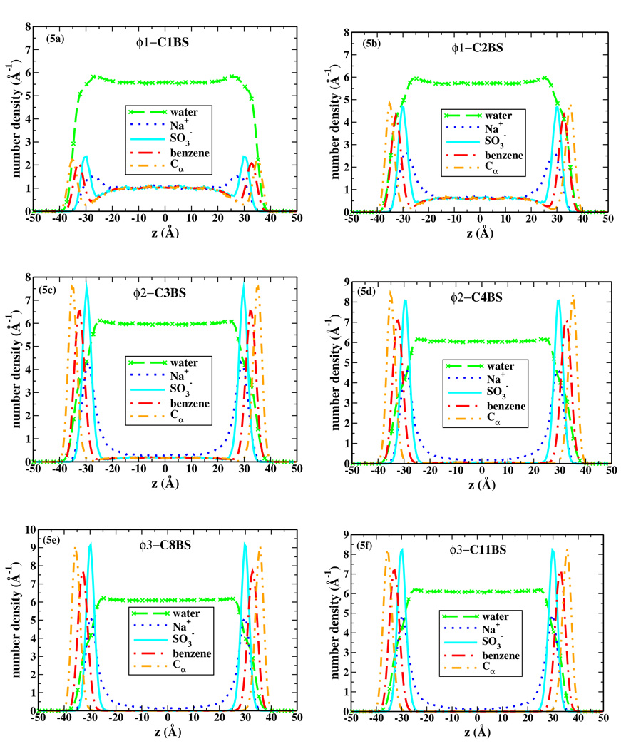
The number density profiles of the water, sodium ion, sulfonate group, benzene ring, and the alpha carbon (Cα) which connects to the benzene ring, from the center of the bulk solution and along the Z axis, are presented in Figure 5 for selected systems. We note that the density distributions of the two monolayers in all systems are symmetric. Each density profile shows a flat density region of bulk water in the middle, approximately from −20 Å to 20 Å. At the water/air interfaces, the water density increases slightly at around z ≈ ± 26 Å, before gradually decreasing to zero at positions z ≈ ± 40 Å. This small density increase is caused by water molecules attracted by the layers of charged headgroups and their counterions. This effect was not found in previous MD simulations of ionic surfactant monolayers at the water/air interface in which the simulation time was around 1 ns, 16,17,19,20 but was found in simulations extending to 5 ns or longer.18,39 For LAS homologues and isomers with long tails (carbon number n >= 5 in the alkyl chain), all surfactants remained at the interfaces with none diffusing into the bulk water region during the whole simulation processes. However, for LAS homologues and isomers with shorter tails (n <= 4 in the alkyl chain), some of the surfactant molecules dissolved into the solvent. The shorter the alkyl chain, the more LAS molecules moved into the bulk. This agrees with the general trend of solubility of surfactants, which is that the solubility increases as the length of the hydrophobic tail decreases.
Figure 5.
Density profile along the Z axis for selected simulation systems. The names of systems are shown at the up-middle positions of each panel. The profiles for water are divided by 12.
The maxima of the density plots of sulfonates, benzene rings and carbons in the alkyl chains are located, respectively, from the water side to the vapor side in sequence. It is not surprising that the sulfonate headgroups for all systems are completely hydrated as seen in the density profiles, where water penetrates well beyond the sulfonate headgroups. On the other hand, it is interesting to note that the water extends into the surfactant monolayer beyond the maximum of the benzene components. In fact, the benzene and water densities decay to zero at approximately the same positions (the densities of water in Figure 5 are divided by 12). The interaction between the alpha carbons and water is less distinctive. The density profiles for other carbon atoms in the alkyl chain are not shown in Figure 5 for clarity. They are either partially hydrated or mostly excluded from the water layer.
Figure 5 also shows a diffuse electrical double layer at each interface formed by a negatively charged diffuse barrier of sulfonate heads and a positively charged diffuse barrier of sodium counterions. The density distribution of sodium ions is located mainly near the sulfonates, but some of the ions diffuse through out the bulk water even for long-chain LAS remaining at the interfaces.
The distributions of surfactant groups at the water surfaces can be well fitted by a Gaussian function:
| (2) |
where Ns is a constant which in fact refers to the number of atoms (groups) in each monolayer peak, zc is the position of the peak center, σ is the standard deviation which shows the width of each peak.
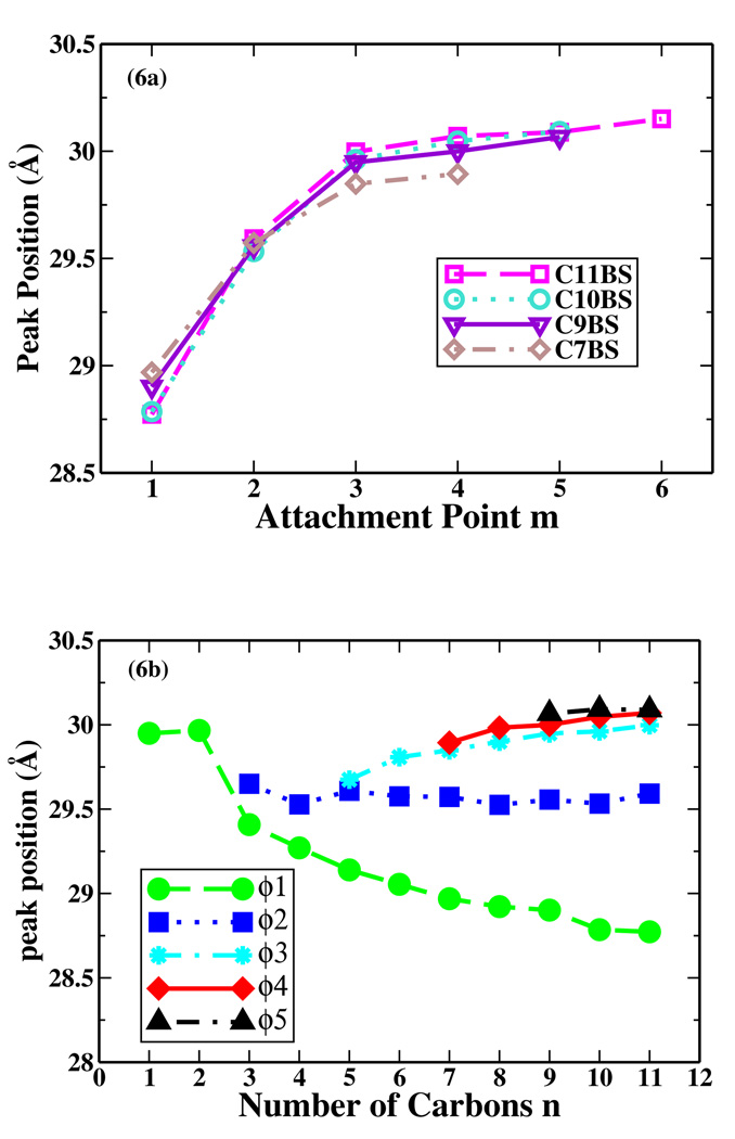
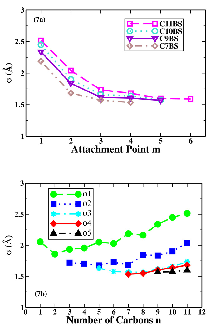
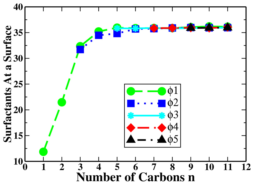
We fit the density profile of sulfonates of each simulated system to Equation (2) averaging over both monolayers, and the obtained values of zc, σ and Ns are displayed in Figure 6, 7, and 8, respectively. Figure 6a shows the average of the absolute values of the sulfonate peak positions in the headgroups of isomers of C7BS, C9BS, C10BS and C11BS. As the alpha carbon moves from the end of the alkyl chain to the middle carbons, the peak position moves away from the water phase for LAS isomers with the same length of the alkyl chain. However, for LAS homologues with the same attachment point of benzene ring, as the length of the alky chain increases (Figure 6b), the peak position of Φ1 series moves toward to the water layer, that of Φ2 series almost keeps the same z value, but Φ3, Φ4, and Φ5 series moves away from the water layer.
Figure 6.
The absolute peak positions of sulfonates versus: (a) the benzene attachment point along the alkyl chain; (b) the number of carbon atoms in the alkyl chain.
Figure 7.
The σ of the sulfonate peaks versus: (a) the benzene attachment point along the alkyl chain; (b) the number of carbon atoms in the alkyl chain.
Figure 8.
The number of surfactant molecules remained at one water/air interface versus the number of carbon atoms in the alkyl chain.
Figure 7a shows the σ of isomers of C7BS, C9BS, C10BS and C11BS. As the alpha carbon moves from the end of the alkyl chain to the middle carbons, σ decreases for LAS isomers with the same length of the alkyl chain. However, for LAS homologues with the same attachment point of the benzene ring, as the length of the alky chain increases, σ first decreases and then increases, in a zig-zag fashion resulting from the odd-even chain length effects (Figure 7b).
As may be seen from Figure 8 as the number of carbon atoms in the alkyl tail increases from 1 to 5, the number of sulfonate groups (hence the number of LAS molecules) Ns at each water surface increases. When the carbon number n >= 5, Ns reaches the plateau value (Ns ≈ 36), which is the total number of LAS molecules originally put at one interface and which means that LAS molecules with a alkyl tail longer than 5 carbons always remained at the water surfaces during the simulation time as mentioned above. The results from Figures 4, 5, and 8 demonstrate the trend of solubility for LAS molecules: the shorter the alkyl chain, the higher the solubility. Toluene-sulfonate (Φ1-C1BS), and cumene-sulfonate (Φ2-C3BS) are often used as hydrotropes for increasing the solubility of LAS and other ingredients in detergent formulations.36
Solubility and other practical surfactant properties like wetting ability are related but the relationship is not simple.36–38 It is commonly understood that, for the same hydrophilic group, if the hydrophobic tail is shorter, the surfactant is more soluble in water, and it has a smaller tendency to migrate to the interface. So its wetting ability is reduced and surfactant properties are minimal. 36–38 As the hydrophobic group increase in molecular weight, the surfactant becomes less soluble, and adsorption and hence surface active properties are higher. 36–38 If the hydrophobic tail group is too long, the surfactant becomes practically insoluble for use in aqueous medium while the surfactant properties are minimal. Typical surfactant formulations are a compromise between surface active properties and solubility.
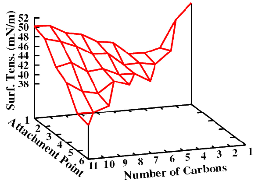
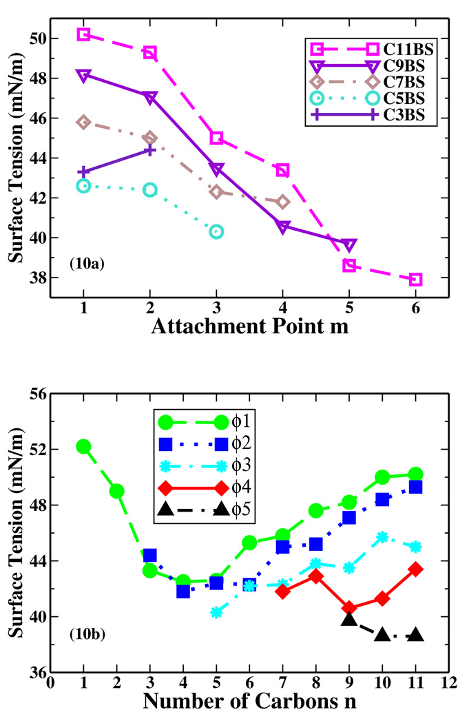
Surface adsorption and reduction of surface tension are the characteristic features and the reason for the wide application of surfactants. We computed the average surface tension (γ) for all systems (Figure 9). The relationship between the surface tension and the number of carbon atoms (n) in the alkyl chain or the attachment point (m) of the benzene ring along the alkyl chain can not be expressed in a simple term. In Figure 10a γ versus m is plotted for various systems. Because Φ2-C3BS is more soluble than Φ1-C3BS, less Φ2-C3BS molecules remained at the interfaces than Φ1-C3BS, therefore γ of Φ2-C3BS is higher than that of Φ1-C3BS. For LAS molecules with alkyl chain longer than 5 carbons, all LAS molecules stayed at the interface. As the benzene attachment point moves to the middle of the alkyl chain, surface tension γ decreases. The relationship between γ and n for LAS homologues is more complicated (Figure 10b). Take the single tail Φ1 series as an example. For systems containing Φ1-C1BS, the surface tension is just slightly lower than that of the pure water system because most of the surfactants moved into the bulk water. As the length of the alkyl tail increases, the surface tension first decreases until n = 4, and then gradually increases. The γ curve also has an odd-even oscillation. The Φ2 series has the same trend with minimum γ at n = 4. The surface tension γ keeps increasing for the odd Φ3 series (Φ3-C5BS, Φ3-C7BS, Φ3-C9BS and Φ3-C11BS), as it does for the even Φ3 series (Φ3-C6BS, Φ3-C8BS and Φ3-C10BS), while γ of odd Φ3 series is lower than neighboring even Φ3 series. As for the Φ4 series, γ increases from Φ4-C7BS to Φ4-C8BS, then sharply goes down for Φ4-C9BS, and then gradually increase through Φ4-C10BS to Φ4-C11BS. The γ for the Φ5 series keeps decreasing from Φ5-C9BS to Φ5-C11BS.
Figure 9.
The calculated surface tension for all monolayers of LAS homologs and isomers.
Figure 10.
(a) Surface tension versus the benzene attachment point on the alkyl chain. (b) Surface tension versus the number of carbon atoms of the alkyl chain.
At first sight it is puzzling to see that some LAS with long alkyl chains, such as Φ1-C11BS and Φ2-C11BS, have a weak ability to lower the surface tension of aqueous solutions. We examined the configurations of all the systems in their equilibrium states. Figure 11 shows the final snapshots of Φ1-C11BS and Φ6-C11BS systems. The strong cohesive forces among the straight hydrocarbon tails of Φ1-C11BS molecules make them aggregate and form surfactant domains at the water/air interface. Part of the water surface is directly exposed to the vacuum. Therefore the calculated surface tension for Φ1-C11BS system is high. In the Φ6-C11BS system, the branched alkyl chains prevent them from aggregating, therefore the Φ6-C11BS molecules cover the full interface and significantly reduce the surface tension of water.
Figure 11.
Final snapshots (top view) of one monolayer of: (a) Φ1-C11BS; (b) Φ6-C11BS. The color scheme for the snapshots is the same as Figure 2.
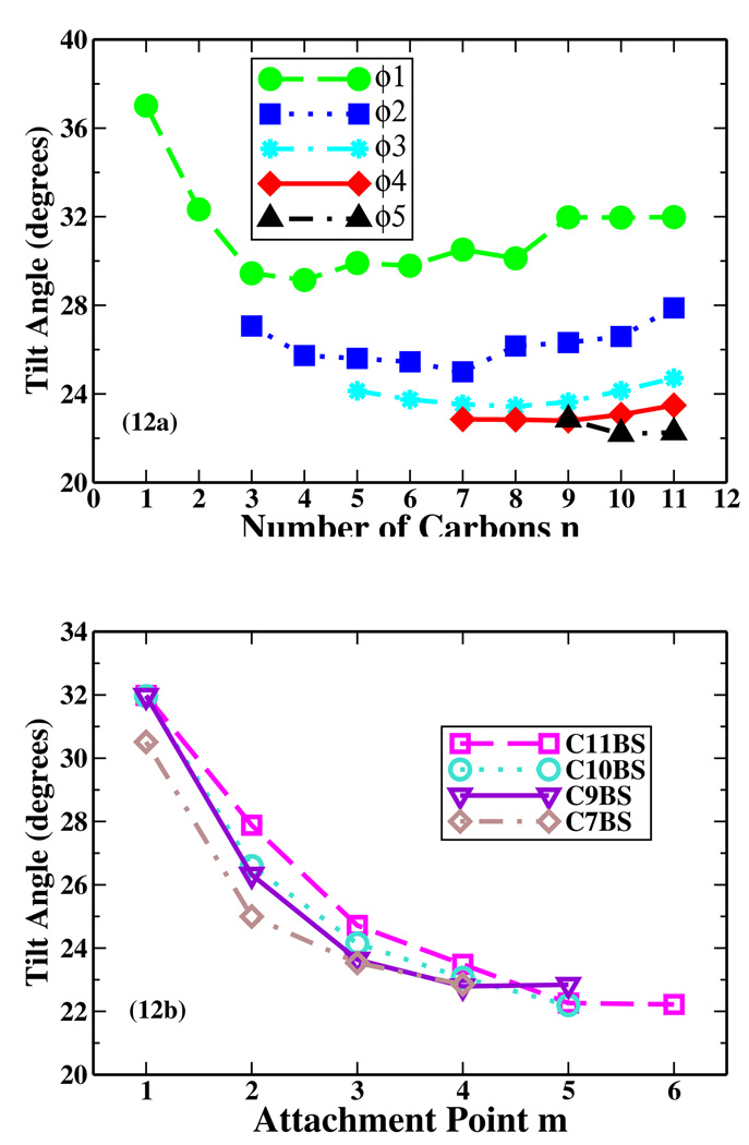
The orientation of the surfactants in a monolayer is another important property, which illustrates the different condensed phases formed by a single layer of amphiphilic molecules. We defined two vectors, the benzene vector and the tail vector, and computed the tilt angles of these two vectors with respect to the monolayer normal (the Z axis), which are referred as θbenzene and θtail, respectively. The benzene vector is defined as the vector from the sulfur atom to the alpha carbon atom. This vector passes through the benzene plane. The tail vector is defined as the vector from the alpha carbon atom to the terminal carbon atom of the longer branch chain pointing to vacuum. From Figure 12a we can see that, for each benzene attachment point, when the carbon number n in the alkyl chain increases, the tilt angle θbenzene firstly decreases and then increases, with minima at 29.1° with Φ1-C4BS for the Φ1 series, 25.0° with Φ2-C7BS for the Φ2 series, 23.4° with Φ3-C8BS for the Φ3 series, and 22.8° with Φ4-C9BS for the Φ4 series. For the Φ5 series, the tilt angle of the benzene vector decreases from Φ5-C9BS to Φ5-C11BS. As the benzene attachment point moves from the terminal carbon of the alkyl chain to the middle carbon, the LAS molecule becomes more symmetrical, and the tilt angle of the benzene vector decreases to ~ 23° (Figure 12a & 12b).
Figure 12.
(a) Tilt angle of the benzene vector versus the number of carbon atoms in the alkyl chain. (b) Tilt angle of the benzene vector versus the benzene attachment point.
MD simulations have been performed on monododecyl pentaethylene glycol (C12E5) monolayers at water/air interfaces with the average area per single surfactant molecule corresponding to the experimental value at CMC.21,23 These simulations suggested that the hydrophobic group of C12E5, which has a single straight tail, presents average tilt angle about 43°. The tilt angle of SDS at a water/air interface is ~47°.17 Other simulations of single-chain surfactants at water/air interface revealed that the mean tilt angle varied around 50°.16–23 These calculated average orientation angles agree well with corresponding experimental data. Our calculated θtail for most of the single straight tail series Φ1-LAS is around 50° except Φ1-C2BS (Figure 13a). Although there are no corresponding experimental data to compare with, our calculated values are within the reasonable range of other single-chain surfactants. It turns out that after reaching thermodynamic equilibrium, the alkyl chains of Φ1-LAS are approximately oriented diagonal to the water/air interface.
Figure 13.
(a) Tilt angle of the tail vector versus the number of carbon atoms in the alkyl chain. (b) Tilt angle of the tail vector versus the benzene attachment point.
The θtail for most of the Φ2-LAS is around 60° except Φ2-C3BS (Figure 13a). For Φ3-LAS, the tail tilt angle decreases from 70 degrees for Φ3-C5BS to 62 degrees for Φ3-C11BS (Figure 13a). Similarly, θtail decreases as the number of carbon atoms increases for the Φ4-LAS and Φ5-LAS series (Figure 13a).
Figure 13b shows θtail for the isomers of C7BS, C8BS, C9BS, C10BS and C11BS. When the benzene attachment point moves from 1 to 4, θtail for C7BS (C8BS) increases from 49° (50°) to 68° (66°). As to C9BS, C10BS and C11BS, θtail increases from Φ1 isomer to Φ3 isomer, then decreases to Φ4 isomer, and then increases until Φ5 or Φ6.
The translational mobility of the surfactant molecules can be investigated by measuring their mean square displacement (MSD) from the MD trajectory. The MSD is defined as:
| (3) |
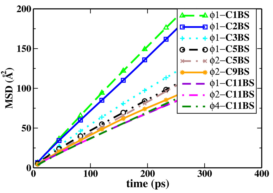
Here, ri(t) denotes the position vector of the center of mass of the surfactant molecules i and N is the number of surfactants. From the atom positions stored in the trajectory data files, we have calculated the average MSD of the mass centers of surfactant molecules, and the results are displayed in Figure 14. We can see that as the carbon number in the alkyl chain increases from 1 to 11, the MSD of Φ1-LAS keeps decreasing. Figure 14 also shows that the benzene attachment point has very little effect on the mobility of C11BS isomers.
Figure 14.
The mean square displacement of selected homologs and isomers of LAS.
4. Conclusions
In the present work, we systematically studied a series of linear alkylbenzene sulfonate (LAS) homologues and isomers at the water/air interface with individual atomistic MD simulations. All LAS molecules have the same headgroup but different hydrophobic tails, and the benzene ring is attached to different carbon atoms of the linear alkyl tail. LAS surfactants with shorter tails are found to have higher solubility and mobility, resulting in less reduction of the surface tension of water. Whereas the homologues with longer tails are less soluble in bulk water, and prefer to stay at the surface. The surface tensions of the systems are related to both the lengths and the degrees of branching of the alkyl chains. The LAS molecules with a straight long tail are also found to have a lower ability to reduce the surface tension because they aggregate and form domains at the water/air interface, leaving part of the water surface directly exposed to vacuum and, therefore, unperturbed. The LAS molecules with long and highly branched tails tend to fully cover the water/air interface and effectively lower the water surface tension. The tilt angle of the LAS molecules varies according to the length and the degree of branching of the alkyl chain.
Although the LAS family is widely used in household applications and in industry, molecular level experimental data are lacking on the pure homologues and isomers due to the complicated mixtures of the LAS products. The formulation of surfactant products are still based on the traditional “trial and error” approach1. Even though there are no experimental data to directly compare to, the AA-MD simulation results of the LAS series in this work provide detailed information revealing the role of molecular topology in surfactant properties, and can be useful for the formulation of surfactant mixtures. With the development of new techniques such as nonlinear vibrational sum frequency spectroscopy, it has become possible to quantitatively probe the details of surfactant interfaces including the orientation and structures of surfactant molecules40–44. The series of LAS molecules can serve as model systems for this kind of detailed molecular level experimental studies in the future.
Acknowledgment
We thank Dr. Kelly L. Anderson at Procter & Gamble Co. for inspiring this project, Dr. Sudip Chakraborty, Dr. Axel Kohlmeyer and Dr. Russell DeVane for helpful discussions.
This work was funded by Procter & Gamble Co., NSF and NIH GM070855 to ADM. Computing resources provided through the DoE INCITE program are gratefully acknowledged.
References
- 1.Myers D. Surfactant Science And Technology. third edition. Hoboken, New Jersey: John Wiley & Sons. Inc.; 2006. [Google Scholar]
- 2.de Almeida JLG, Dufaux M, Taarit YB, Naccache C. J. Am. Oil Chem. Soc. 1994;71:675–694. [Google Scholar]
- 3.Cavalli L, Clerici R, Radici P, Valtorta L. Tens. Surf. Det. 1999;36:254–258. [Google Scholar]
- 4.Holmberg K, Jönsson B, Kronberg B, Lindman B. Surfactants and Polymers in Aqueous Solution. second edition. Chichester, West Sussex, England: John Wiley & Sons Ltd; 2003. [Google Scholar]
- 5.Schoenkaes U. Chim. Oggi. 1998;169:9–13. [Google Scholar]
- 6.Garrett PR, Moore PR. J. Colloid Interf. Sci. 1993;159:214–225. [Google Scholar]
- 7.Cohen L. Tenside Surfact Det. 1998;35:265–269. [Google Scholar]
- 8.van Os NM, Kok R, Bolsman TABM. Tenside Surfact Det. 1992;29:175–189. [Google Scholar]
- 9.Ma JG, Boyd BJ, Drummond CJ. Langmuir. 2006;22:8646–8654. doi: 10.1021/la0602822. [DOI] [PubMed] [Google Scholar]
- 10.Yang J, Zhao Y, Li Z, Qiao W, Cheng L. Energ. Source. 2005;27:1013–1018. [Google Scholar]
- 11.Gragson DE, McCarty BM, Richmond GL. J. Phys. Chem. 1996;100:14272–14275. [Google Scholar]
- 12.Li ZX, Lee EM, Thomas RK, Penfold J. J. Colloid Interf. Sci. 1997;187:492–497. doi: 10.1006/jcis.1996.4713. [DOI] [PubMed] [Google Scholar]
- 13.Lu JR, Thomas RK, Penfold J. Adv. Colloid Interfac. Sci. 2000;84:143–304. doi: 10.1016/s0001-8686(99)00019-6. [DOI] [PubMed] [Google Scholar]
- 14.Kjellin URM, Claesson PM, Linse P. Langmuir. 2002;18:6745–6753. [Google Scholar]
- 15.He W, Liu F, Ye Z, Zhang Y, Guo Z, Zhu L, Zhai X, Li J. Langmuir. 2001;17:1143–1149. [Google Scholar]
- 16.Schweighofer KJ, Essmann U, Berkowitz M. J. Phys. Chem. B. 1997;101:3793–3799. [Google Scholar]
- 17.Dominguez H, Berkowitz ML. J. Phys. Chem. B. 2000;104:5302–5308. [Google Scholar]
- 18.Clavero E, Rodriguez J, Laria D. J. Chem. Phys. 2007;127:124704. doi: 10.1063/1.2779876. [DOI] [PubMed] [Google Scholar]
- 19.Tarek M, Tobias DJ, Klein ML. J. Phys. Chem. 1995;99:1393–1402. [Google Scholar]
- 20.Yuan S, Ma L, Zhang X, Zheng L. Colloid. Surface. A: Physicochem. Eng. Aspects. 2006;289:1–9. [Google Scholar]
- 21.Kuhn H, Rehage H. Colloid Polym. Sci. 2000;278:114–118. [Google Scholar]
- 22.Chanda J, Bandyopadhyay S. J. Chem. Theory Comput. 2005;1:963–971. doi: 10.1021/ct050019y. [DOI] [PubMed] [Google Scholar]
- 23.Cuny V, Antoni M, Arbelot M, Liggieri L. Colloid. Surface. A: Physicochem. Eng. Aspects. 2008;323:180–191. [Google Scholar]
- 24.Tobias DJ, Klein ML. J. Phys. Chem. 1996;100:6637–6648. [Google Scholar]
- 25.Jang SS, Lin ST, Maiti PK, Goddard WA, Shuler P, Tang YC. J. Phys. Chem. B. 2004;108:12130–12140. [Google Scholar]
- 26.Kale L, Skeel R, Bhandarkar M, Brunner R, Gursoy A, Krawetz N, Phillips J, Shinozaki A, Varadarajan K, Schulten K. J. Comput. Phys. 1999;151:283–312. [Google Scholar]
- 27.Jorgensen WL, Chandrashekar J, Mdura JD, Impey R, Klein ML. J. Chem. Phys. 1983;79:926–935. [Google Scholar]
- 28.Klauda JB, Brooks BR, MacKerell AD, Jr, Richard M, Venable RM, Pastor RW. J. Phys. Chem. B. 2005;109:5300–5311. doi: 10.1021/jp0468096. [DOI] [PubMed] [Google Scholar]
- 29.MacKerell AD. J. Comput. Chem. 2004;25:1584–1604. doi: 10.1002/jcc.20082. [DOI] [PubMed] [Google Scholar]
- 30.Darden T, York D, Pederson L. J. Chem. Phys. 1993;98:10089–10092. [Google Scholar]
- 31.Essmann U, Perera L, Berkowitz ML, Darden T, Lee H, Pederson LG. J. Chem. Phys. 1995;103:8577–8593. [Google Scholar]
- 32.Ryckaert JP, Ciccotti G, Berendson HJC. J. Comput. Phys. 1977;23:327–341. [Google Scholar]
- 33.Andersen HC. J. Comput. Phys. 1983;52:24–34. [Google Scholar]
- 34.Vega C, de Miguel E. J. Chem. Phys. 2007;126:154707. doi: 10.1063/1.2715577. [DOI] [PubMed] [Google Scholar]
- 35.Chen F, Smith PE. J. Chem. Phys. 2007;126:221101. doi: 10.1063/1.2745718. [DOI] [PubMed] [Google Scholar]
- 36.Rosen MJ. Surfactants and interfacial phenomena. second edition. John Wiley & Sons, Inc.; 1989. [Google Scholar]
- 37.Porter MR. Handbook of Surfactants. second edition. London: Blackie Academic & Professional; 1994. [Google Scholar]
- 38.Stache HW. Anionic Surfactants -- Organic Chemistry. New York: Marcel Dekker; 1996. [Google Scholar]
- 39.Dominguez H. J. Phys. Chem. B. 2006;110:13151. doi: 10.1021/jp062018n. [DOI] [PubMed] [Google Scholar]
- 40.Voss LF, Hadad CM, Allen HC. J. Phys. Chem. B. 2006;110:19487–19490. doi: 10.1021/jp062595b. [DOI] [PubMed] [Google Scholar]
- 41.Harper KL, Allen HC. Langmuir. 2007;23:8925–8931. doi: 10.1021/la7006974. [DOI] [PubMed] [Google Scholar]
- 42.Schrödle S, Richmond GL. J. Am. Chem. Soc. 2008;130:5072–5085. doi: 10.1021/ja076664r. [DOI] [PubMed] [Google Scholar]
- 43.Tyrode E, Rutland MW, Bain CD. J. Am. Chem. Soc. 2008;130:17434–17445. doi: 10.1021/ja805169z. [DOI] [PubMed] [Google Scholar]
- 44.Sovago M, Vartiainen E, Bonn M. J. Phys. Chem. C. 2009;113:6100–6106. doi: 10.1063/1.3257600. [DOI] [PubMed] [Google Scholar]


