Abstract
Silver nanocubes with edge lengths controllable in the range of 30–200 nm were synthesized using an approach based on seeded growth. The key to the success of this synthesis is the use of single-crystal Ag seeds to direct the growth and the use of AgNO3 as a precursor to elemental Ag where the by-product HNO3 can block both the homogeneous nucleation and evolution of single-crystal seeds into twinned nanoparticles. Either spherical (in the shape of cubooctahedron) or cubic seeds could be employed for this growth process. The edge length of resultant Ag nanocubes can be readily controlled by varying the amount of Ag seeds used, the amount of AgNO3 added, or both. For the first time, we could obtain Ag nanocubes with uniform edge lengths controllable in the range of 30–200 nm and then compare their localized surface plasmon resonance and surface-enhanced Raman scattering properties.
Keywords: seed-mediated growth, oxidative etching, size control, surface-enhanced Raman scattering
Introduction
Noble-metal nanocrystals have been extensively studied in recent years due to their unique physical and chemical properties substantially different from bulk materials.1–6 Silver, a noble metal historically used in the fabrication of ornaments, electrical conductors, mirrors, photographic films, and antimicrobial coatings,7–11 has received ever increasing attention in the form of nanocrystals because of their superior performance in various applications such as catalysis, electronics, optical labeling, and biosensing.12–15 A wide variety of methods have been developed for synthesizing Ag nanocrystals with different shapes such as sphere, cube, bipyramid, decahedron, bar, and rod/wire with a pentagonal cross section.16–22 Among them, Ag nanocubes have received particular interest due to their great potential as catalysts for epoxidation reactions, substrates for plasmonic sensing, substrates for surface-enhanced Raman scattering (SERS), building blocks for self-assembly, and sacrificial templates for generating gold nanocages.23–27
Thanks to the efforts from a large number of research groups, a wealth of methods are now available for generating Ag nanocubes.28–36 However, it is still very difficult to find a method that can be conveniently applied to synthesize Ag nanocubes with controllable edge lengths over a broad range. In this article, we report a simple and robust approach based on seeded growth for producing Ag nanocubes with edge lengths tunable and controllable in the range of 30–200 nm. In a typical synthesis, single-crystal Ag seeds in a spherical or cubic shape were first prepared using a polyol process recently developed by our group that used CF3COOAg as a precursor to elemental Ag.37 The seeds were collected and then mixed with AgNO3 in ethylene glycol at an elevated temperature to form Ag nanocubes. Our mechanistic studies indicate that oxidative etching played an important role in the seed-mediated growth of Ag nanocubes. When AgNO3 was used for the polyol process, HNO3 was formed during the synthesis,38 which could serve as an oxidative etchant to block the homogeneous nucleation of Ag atoms and the evolution of single-crystal seeds into twinned nanoparticles. The size of the resultant Ag nanocubes could be reliably controlled by any one the following means: i) quenching the reaction once the localized surface plasmon resonance (LSPR) peak had reached a specific position; ii) varying the amount of AgNO3 precursor mixed with a specific quantity of Ag seeds; and iii) varying the quantity of Ag seeds added into a specific amount of AgNO3 precursor. These Ag nanocubes with highly tunable and controllable sizes allowed us to systematically investigate the size effect for both LSPR and SERS properties.
Experiment section
Preparation of Different Types of Single-Crystal Seeds
Single-crystal seeds of Ag were prepared using a recently reported polyol process, with ethylene glycol (EG, J. T. Baker, Lot No. G32B27) as the solvent and silver trifluoroacetate (CF3COOAg, Aldrich, 04514TH) as a precursor to elemental silver.37 In a typical synthesis, 5 mL ethylene glycol was added into a 100-mL round bottom flask (ACE Glass) and heated under magnetic stirring in an oil bath pre-set to 150 °C, and then 0.06 mL NaHS (3 mM in EG, Aldrich, 02326AH) was quickly injected. After 2 min, 0.5 mL HCl (3 mM in EG, Aldrich, cat. no. 01158CJ) was injected into the heated solution, followed by the addition of 1.25 mL of poly(vinyl pyrrolidone) (PVP, 20 mg/mL in EG, MW ≈ 55,000, Aldrich). After another 2 min, 0.4 mL CF3COOAg (282 mM in EG) was added into the mixture. During the entire process, the flask was capped with a glass stopper except the addition of reagents. The spherical and cubic seeds were obtained by quenching the reaction with an ice-water bath when the major LSPR peak of the Ag seeds had reached 399 nm and 435 nm, respectively. After centrifugation and washing with acetone and de-ionized (DI) water three times, the seeds were stored in EG. The particle concentration of Ag seeds was determined using a combination of TEM imaging (for size measurement) and inductively coupled plasma mass spectrometry (ICP-MS, for the Ag concentration). The sample for ICP-MS (Agilent 7500 CE) was prepared by dissolving 10 μL of the suspension of Ag seeds with 30 μL of concentrated HNO3. The resultant solution was further diluted to a level of 100 ppb for ICP-MS analysis.
Seed-Mediated Growth of Ag Nanocubes
In a standard synthesis, 1.25 mL of EG was held in a 20 mL glass vial and heated in an oil bath at 150 °C under magnetic stirring. After 1.5 min, 0.3 mL of a PVP solution in EG (20 mg/mL) was added. After another 1.5 min, 50 μL of the as-prepared single-crystal Ag seeds (1.1×10¹² particles/mL) in EG solution was introduced, followed by the addition of 200 μL of silver nitrate (AgNO3, Aldrich) solution in EG (282 mM). Aliquots were taken at different reaction stages of a synthesis using glass pipettes, and then quickly injected into cool acetone held in 1.5-mL centrifuge tubes. The growth was terminated after 3 h by quenching with an ice-water bath. All the products were centrifuged, followed by washing with acetone and DI water to remove excess EG and PVP. The final product was dispersed in DI water.
Solution-Phase SERS Measurements
The as-prepared samples of Ag nanocubes were first characterized by SERS prior to surface functionalization. After washing with DI water, 50 μL of the suspension of Ag nanocubes were placed in a small measurement vessel and covered with a glass cover slip. The cover slip prevented water evaporation and served as a reference point from which the focal volume was lowered 200 μm into the solution.
Correlated SERS and SEM Experiments
In a typical procedure, a small aliquot of the as-prepared Ag nanocubes (dispersed in water, 3 μL) was mixed with 30 μL of 1 mM solution of 1,4-benzenedithiol(1,4-BDT, Aldrich) in ethanol for 1 h. Then, the sample for correlated SEM and SERS experiments were prepared by drop-casting the ethanol solution containing Ag nanocubes and 1,4-BDT on a Si substrate that had been patterned with registration marks and letting it dry under ambient conditions. Once the sample had dried, it was rinsed with copious amounts of ethanol. The sample was immediately employed for SERS measurements after preparation, by following a previously reported protocol.39
Instrumentation
The TEM images were captured using a microscope (FEI G2 Spirit Twin) operated at 120 kV. High-resolution TEM images were obtained using a JEOL 2100F operated at 200 kV. The SEM images were taken using a field-emission microscope (FEI, Nova NanoSEM 230) operated at an accelerating voltage of 10–20 kV. The UV-vis spectra were taken using a Cary 50 spectrophotometer (Palo Alto, CA). The SERS spectra were recorded using a Renishaw inVia confocal Raman spectrometer coupled to a Leica microscope with a 50× objective (NA=0.90) in the backscattering configuration. The 514-nm excitation source was obtained from an argon laser coupled to a holographic notch filter with a grating of 1200 lines per millimeter. Additionally, solution-phase measurements were made using a 785-nm excitation source generated by a diode laser coupled to a holographic notch filter with a grating of 1200 lines per millimeter. The backscattered Raman signals were collected on a thermoelectrically cooled (−60 °C) CCD detector. The scattering spectra for substrate-supported samples were recorded in the range of 550–1800 cm−1, in one acquisition of 20 s accumulation, and 0.5 mW of laser power at the sample. For solution-phase samples, the spectra were collected in the range of 550–1100 cm−1 with a laser power of 5 mW and 60 s accumulation.
Results and Discussion
Comparison of Different Seeds and Different Precursors to Silver
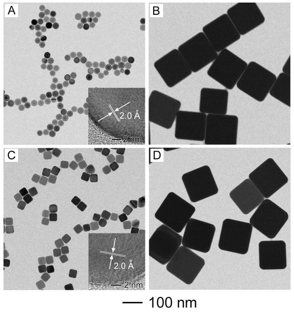
Figure 1 shows TEM images of two different types of single-crystal Ag seeds and the Ag nanocubes grown from these seeds. The spherical (Fig. 1A) and cubic (Fig. 1C) seeds were prepared using a new protocol recently developed in our group, which involved the use of CF3COOAg as a precursor to elemental Ag.37 The seeds were 29±1 nm in diameter and 39±2 nm in edge length, and they were obtained, respectively, by stopping the reaction once the extinction peaks of the reaction solution had reached 399 and 435 nm. The high-resolution TEM images (insets of Fig. 1, A and C) taken from these two types of seeds both gave a lattice fringe spacing of 2.0 Ǻ, which was consistent with the spacing between the {200} planes of face-centered cubic (fcc) Ag.28 These results confirm that the spherical and cubic Ag seeds were both single crystalline in structure. When 200 μL of AgNO3 solution (282 mM) was added into suspensions of the seeds as a source of Ag, the spherical and cubic seeds grew into Ag nanocubes with an edge length of 154±5 and 155±6 nm (Fig. 1, B and D), respectively. The TEM images suggest that the Ag nanocubes had a uniform distribution in terms of both shape and size. It is worth pointing out the Ag nanocubes obtained from these two different types of seeds had essentially the same edge length even though the sizes of the initial seeds were different by 10 nm. This result suggests that the added AgNO3 was not completely consumed during the growth process. Otherwise, the larger seeds are supposed to generate Ag nanocubes with longer edge lengths (see the discussion in the next section).
Figure 1.
TEM images of two different types of single-crystal Ag seeds and Ag nanocubes obtained from these seeds: (A, B) spherical seeds and the resultant nanocubes, respectively; and (C, D) cubic seeds and the resultant nanocubes, respectively. In a typical synthesis, 200 μL AgNO3 (282 mM) was added to 50 μL of spherical (1.1×10¹² particles/mL) or cubic (1.1×10¹² particles/mL) seeds, and the reaction was terminated in 3 h.
For the purpose of testing different precursors to elemental Ag, CF3COOAg instead of AgNO3 was also used for the growth while other parameters were kept the same. However, essentially no Ag nanocubes could be found in the final products. Instead, we obtained Ag nanoparticles with irregular shapes and poorly controlled sizes (Fig. S1A). As discussed in our previous publication,36 when AgNO3 was used as a precursor, the small amount of HNO3 generated during polyol reduction could serve as an oxidative etchant to dissolve any twinned particles that might evolve from single-crystal seeds. The presence of HNO3 could also help block homogeneous nucleation from the added AgNO3, which might lead to the production of twinned seeds and polydispersed samples. In comparison, the small amount of CF3COOH resulting from CF3COOAg precursor and polyol reduction has no oxidative etching power. It could not prevent the single-crystal Ag seeds from evolving into twinned nanoparticles; neither could it block the homogeneous nucleation process. As a result, twinned particles with irregular, poorly defined shapes could easily form during the seeded growth process (Fig. S1A). This observation is consistent with our previous study where Ag nanocubes could not be obtained by only adding CF3COOAg to a polyol process.37 When we introduced a trace amount of HCl into the seeded synthesis to provide an oxidative etchant by combining with the O2 from air,36 we found that a small portion of Ag nanocubes with an edge length of about 115 nm could be found in the final product, in addition to the irregularly shaped Ag particles (Fig. S1B). In this case, the Ag nanocubes evolved from the added single-crystal Ag seeds while the irregular particles most likely grew from the twinned seeds that were formed during the introduction of CF3COOAg.
Supply and Consumption of the AgNO3 Precursor
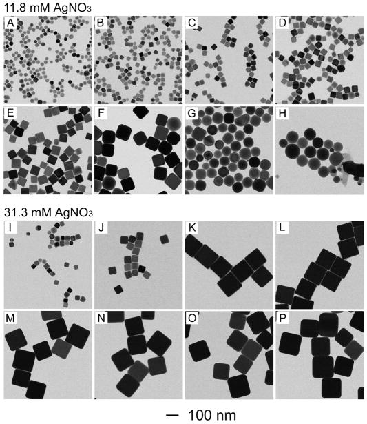
In order to better understand the mechanism involved in the seed-mediated growth of Ag nanocubes, we took aliquots at different time points from the two syntheses that both used spherical Ag seeds, but with AgNO3 at different concentrations in the reaction solution. The top panel in Figure 2 shows TEM images of the Ag nanoparticles sampled from the synthesis where 75 μL of 282 mM AgNO3 solution and 125 μL EG were introduced with other parameters being kept the same as the synthesis shown in Figure 1. The concentration of AgNO3 in the final reaction solution was 11.8 mM. At t=10 min, the spherical Ag seeds (Fig. 1A) had already evolved into nanocubes with rounded corners (Fig. 2A), with the edge length (~30 nm) of these nanocubes being essentially the same as the diameter (~29 nm) of the spherical seeds. This observation indicates that the Ag atoms were mainly added to the corners of the seeds in the early stage of growth. It should be pointed out that the spherical Ag seeds were essentially cubooctahedrons with a mix of both {100} and {111} facets on the surface.40 They can grow into nanocrystals with different shapes, including cubes, truncated cubes, and octahedrons depending on the ratio of growth rates along <111> and <100> directions.41 In this case, the spherical Ag seeds grew into nanocubes because the PVP added as a stabilizer could bind to the {100} facets of Ag more strongly than other facets.42 After the addition of AgNO3 for 20 min, the product sampled from the reaction solution had grown into Ag nanocubes of 35 nm in edge length together with sharp corners (Fig. 2B). When the reaction proceeded to t=3 h, the Ag nanocubes had been further enlarged to an edge length of 97 nm (Fig. 2F). At the same time, the nanocubes became slightly truncated at corners. The truncation could be attributed to the higher energies of corner sites relative to the side faces. Once the production of Ag atoms via reduction of AgNO3 had ceased, there would be a strong tendency for the sharp corners to become rounded through Ostwald ripening. At t=4 h, most of the Ag nanocubes had their corners considerably truncated, so they looked more like nanospheres (Fig. 2G). The diameter of the nanosphere was essentially the same as the edge length of the nanocubes. When the reaction was further prolonged to t=5 h, essentially all the Ag nanocubes had evolved into nanospheres (Fig. 2H).
Figure 2.
TEM images of samples obtained at different stages of two syntheses, where the same amount of seeds (spherical, 50 μL, and 1.1×10¹² particles/mL) was used, but AgNO3 solutions of two different concentrations were used: (A, I) 10 min, (B, J) 20 min, (C, K) 40 min, (D, L) 1 h, (E, M) 2 h, (F, N) 3 h, (G, O) 4 h, and (H, P) 5 h.
The bottom panel in Figure 2 shows TEM images of Ag nanocubes taken from a similar synthesis where 200 μL of 282 mM AgNO3 solution was used. The concentration of AgNO3 in the final reaction solution was increased to 31.3 mM. In this case, the Ag seeds grew very quickly at the early stage. The edge length of the Ag nanocubes was increased to 133 nm within 40 min (Fig. 2K) and finally to 162 nm at t=5 h. It is worth pointing out that the Ag nanocubes could maintain their sharp corners up to t=5 h due to the presence of a larger amount of AgNO3 in the reaction solution and prolonged production of Ag atoms.
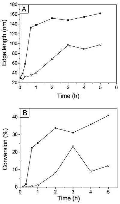
To gain insights on the growth mechanism, we plotted the edge length of Ag nanocubes and the percentage of conversion for AgNO3 (calculated from the changes in volume for the Ag seeds) as a function of the reaction time. As shown in Figure 3A, the Ag nanocubes grew much faster in size when the concentration of AgNO3 in the reaction solution was increased from 11.8 mM to 31.3 mM. At 31.3 mM, the edge length of the Ag nanocubes quickly increased to 133 nm after the reaction had only processed for 40 min while the edge length of the Ag nanocubes only increased to 35 nm for the 11.8 mM case. After the fast-growth stage, the synthesis with 31.3 mM AgNO3 went into a slow growth process that continued until the end of the reaction. The edge length of the Ag nanocubes only increased from 133 to 162 nm during this growth plateau. In contrast to the synthesis with 31.3 mM AgNO3, the Ag nanocubes grew slowly and continuously in the case of 11.8 mM AgNO3. The edge length of the Ag nanocubes gradually increased from 30 to 97 nm within the first 3 hours. After that, the Ag nanocubes became truncated at the corners and finally evolved into nanospheres. The conversion of AgNO3 into Ag in the synthesis with 31.3 mM AgNO3 also increased quickly in the early stage, and finally reached the maximum percentage of 40.9% at a reaction time of 5 h. In the synthesis with 11.8 mM AgNO3, the conversion of AgNO3 reached the maximum percentage of 23.2% at a reaction time of 3 h, but then decreased to 8.9% at a reaction time of 4 h. This decrease can be attributed to oxidation of Ag into Ag+ ions during the truncation of corners for the Ag nanocubes.
Figure 3.
Plots of edge length of Ag nanocubes and percentage of conversion of AgNO3 as a function of reaction time for the two syntheses shown in Figure 2. The curves with hollow and solid symbols correspond to syntheses with the use of 11.8 mM and 31.3 mM AgNO3 solutions, respectively.
It is well known that the synthesis of metal nanocrystal is a dynamic process that involves interplay of both growth and dissolution.2 During growth, Ag atoms were added onto the Ag seeds or nanocubes and the remaining Ag+ ions in the reaction solution would be reduced, together with an increase for the generated HNO3. As a result, oxidative etching of Ag by the HNO3 was expected to increase in terms of dominance. For the synthesis with 11.8 mM AgNO3, the dissolution of Ag caused by HNO3 overcame the growth caused by reduction of AgNO3 at t=3 h, so the Ag nanocubes started to be truncated at corners to form nanospheres. For the synthesis with 31.3 mM AgNO3, the concentration of AgNO3 also decreased (to 21.6 mM at t=3 h), but it was still much higher than the concentration of AgNO3 (9.1 mM) in the case of 11.8 mM AgNO3. As a result, the Ag nanocubes in the reaction with 31.3 mM AgNO3 could keep their sharp corners from being truncated (Fig. 2, N–P). To verify the oxidative etching role of HNO3 in this synthesis, we added a small amount of HNO3 to a typical synthesis after the reaction had continued for 20 min. The product obtained at a reaction time of 1.5 h consisted of Ag nanocubes with rounded corners, Ag nanospheres, and a small number of Ag nanocubes with sharp corners (Fig. S2). This observation suggests that HNO3 indeed played an important role in the evolution from Ag nanocubes to nanospheres.
Size Control for the Silver Nanocubes
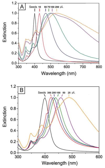
The results described in Figure 2 suggest a simple method for controlling the size of the Ag nanocubes by stopping the synthesis at different reaction times. In addition to this method, we could vary the sizes of Ag nanocubes in a better controlled fashion by adjusting the amounts of Ag seeds and/or AgNO3 added into the reaction system. Figure 4, A–E, shows TEM images of Ag nanocubes with different sizes that were obtained by adding different amounts of AgNO3 into reaction solutions that contained the same amount of single-crystal Ag seeds. All the syntheses were stopped at t=3 h. The edge length of these Ag nanocubes increased from 36 to 58, 99, 144, and 172 nm, respectively, when the amount of AgNO3 added into the reaction solution increased from 10 to 50, 75, 100, and 200 μL. As shown in Figure 5A, the major LSPR peaks of these Ag nanocubes displayed a continuous red-shift from 430 to 468, 497, 513, and 537 nm. The Ag nanocubes obtained from the reactions with the addition of 50, 75, 100, and 200 μL AgNO3 showed relatively broad LSPR peaks, which could be attributed to their large sizes and thus the involvement of multipode excitations in addition to dipole excitation.43 Figure 4, F–J, shows TEM images of Ag nanocubes with edge lengths increasing from 38, to 40, 45, 56, and 76 nm that were obtained by adding 300, 200, 100, 50, and 20 μL of the single-crystal Ag seeds to the reaction solutions, followed by the addition of 50 μL AgNO3. All the syntheses were stopped at t=3 h. As the number of Ag seeds in the reaction solution was reduced, the edge length of the Ag nanocubes was increased. As shown in Figure 5B, the major LSPR peaks of these Ag nanocubes also exhibited a continuous red-shift from 400 to 489 nm as their edge lengths were increased. The results above suggest that both the methods of quenching the reaction at different time and varying the amount of AgNO3 precursor added into the reaction solution provided us the reliable and precise routes to adjust Ag nanocubes in a broad range of sizes.
Figure 4.
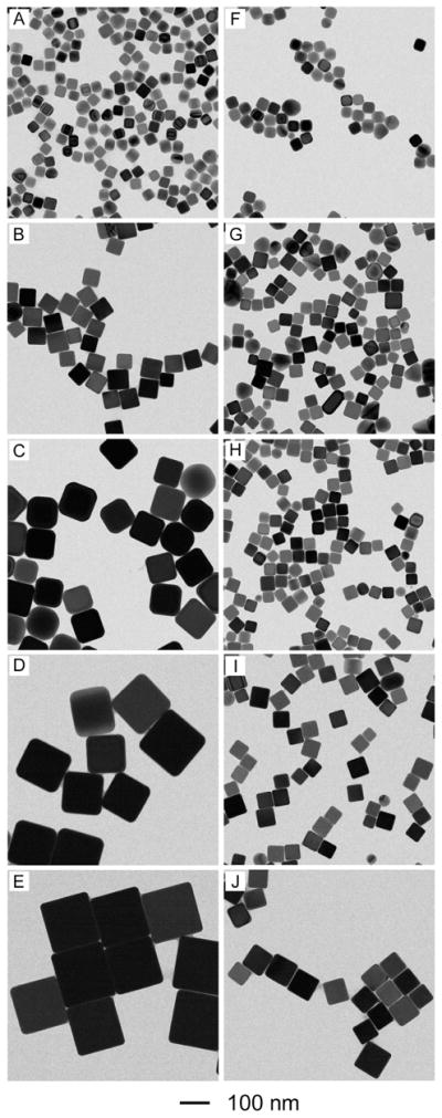
Size control over Ag nanocubes by adding different amounts of AgNO3 (the left volume), and single-crystal seeds (the right volume), respectively. (A–E) 10, 50, 75, 100, and 200 μL AgNO3 was added to 50 μL of spherical seeds (1.1×10¹² particles/mL); (F–J) 300, 200, 100, 50, and 20 μL of the spherical seeds (1.1×10¹² particles/mL) was used with 50 μL AgNO3 solution (282 mM).
Figure 5.
UV-vis spectra taken from products of the syntheses shown in Figure 4: (A) adding different amounts (as indicated on the curves) of AgNO3 to the same amount of spherical seeds; and (B) adding different amounts (as indicated on the curves) of spherical seeds to the same amount of AgNO3 solution.
Additionally, Figure 6 shows that the intensity of SERS bands from PVP adsorbed on the surface of the Ag nanocube increased as the edge length increased. This is a clear indication that PVP remained on the surface of the Ag nanocubes to stabilize the colloidal solution post-synthesis. The surface area of the cube increases in proportion to the square of the edge length, which allows a greater number of PVP molecules to adsorb to the larger cubes. Since the particle concentration was essentially the same for all different samples (as determined by the concentration of the Ag seeds), the SERS signals were supposed to be stronger as the nanocubes became bigger. Some of the key vibrational bands of PVP that increased with edge length were the pyrrolidone ring breathing modes at 841 and 862 cm−1 and the rocking mode of CH2 groups on the pyrrolidone ring at 936 cm−1.44
Figure 6.
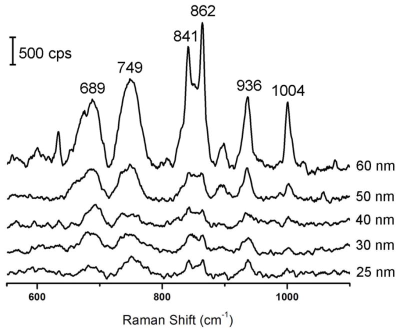
Solution-phase SERS spectra of the as-prepared Ag nanocubes with five different edge lengths as labeled on the plot. Band assignments for PVP are as follows: C-C stretch (689 cm−1), pyrrolidone ring torsion (749 cm−1), pyrrolidone ring breathing mode (841 and 862 cm−1), CH2 ring rocking mode (936 cm−1), and backbone CH2 deformation (1004 cm−1). cps=counts per second.
SERS Properties of Silver Nanocubes with Different Sizes
We further performed SERS measurements with a standard probe molecule for Ag nanocubes with different edge lengths. We used 1,4-BDT as the probe molecule because it is known to form a well-defined monolayer on the Ag surface with a characteristic molecular footprint, which is critical for estimating the total number of molecules probed in the SERS measurement and thus to calculate the enhancement factor (EF). Figure 7 shows the SERS spectra recorded from individual Ag cubes with four different edge lengths: 57 nm, 82 nm, 125 nm, and 170 nm (from bottom to top in the plot). The insets show the corresponding SEM images. In Figure 7A, the nanocubes were oriented with one of their edges parallel to the laser polarization. The strong peak located at 1562 cm−1 can be assigned to the phenyl ring stretching motion (8a vibrational mode), while the weak peak at 1181 cm−1 can be attributed to the CH bending motion (9a vibrational mode).45,46 The broad band at 900–1000 cm−1 came from the Si substrate. In addition, the SERS spectra for 1,4-BDT showed a broad band from 1056 to 1086 cm−1. This is because the ordinary Raman spectrum of 1,4-BDT displays two bands in this region (1080 and 1065 cm−1), which tend to broaden and overlap in the SERS spectrum owing to the interactions between the Ag surface and the π-orbital system of the benzene ring.45,46 It is clear that the intensity of the characteristic 1,4-BDT SERS peaks increased with increasing edge length for the cubes: 57 nm < 82 nm < 125 nm < 170 nm. The intensity of SERS signal for the 170-nm cube was about 12 times stronger than that of the 57-nm cube. The same trend was also observed when the nanocubes were orientated with one of its face diagonals parallel to the laser polarization (Figure 7B). Moreover, it should be pointed out that the scale bar for the intensity (with the same counts per second or cps) shown in Figure 7B is shorter than that in Figure 7A. This reveals that the intensity of the SERS signal from each cube was much stronger when one of its face diagonals rather than the edge was oriented parallel to the laser polarization. Figure S3 shows a typical comparison of SERS spectra of the 82-nm cube along these two polarizations displayed in one figure. It can be clearly seen that the intensity of the SERS signal with the laser polarization along a face diagonal of the cube is about two times stronger than that with laser polarization along an edge of the cube. The same trend was also observed for Ag nanocubes with other edge lengths. As previously reported by our group, the SERS signals taken from a single Ag nanocube had a strong dependence on the laser polarization, which could be attributed to the difference in near-field distribution over the surface of a nanocube under different polarization directions.39
Figure 7.
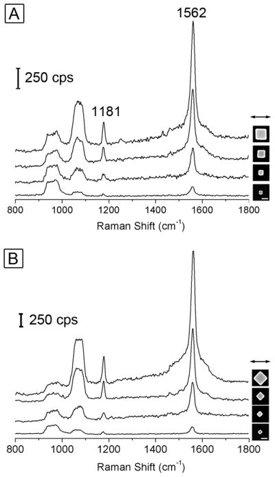
SERS spectra recorded from Ag cubes with four different edge lengths: 57 nm, 82 nm, 125 nm, and 170 nm (from bottom to top in the plot) under two laser polarization directions: (A) along an edge and (B) along a face diagonal. The scale bars in the insets correspond to 100 nm and are applied to all the images. cps=counts per second.
We employed the peak at 1562 cm−1 (the strongest band in the spectra) to estimate the EF through the following equation:
| (1) |
where ISERS and Ibulk are the intensities of the same band for the SERS and bulk spectra, Nbulk is the number of bulk molecules probed for a bulk sample, and NSERS is the number of molecules probed in the SERS spectrum. The intensities ISERS and Ibulk were determined by the areas of the 1562 cm−1 band. Nbulk was calculated based on the Raman spectrum of a 0.1 M 1,4-BDT solution in 12 M NaOH(aq) and the focal volume of our Raman system (1.48 picoL). NSERS was determined according to the assumption that a monolayer of 1,4-MBT molecules was formed on the surface of Ag with 0.54 nm2 molecular footprint.45,46 The NSERS here represents a theoretical maximum number of molecules. Therefore, the actual EF is supposed to be higher than the value reported here. Table 1 summarizes the EFs calculated for single Ag nanocubes with different edge lengths under two laser polarization directions: along an edge and along a face diagonal, respectively. We can see that the EFs for the cubes actually did not change a lot with the increasing edge length. The EFs of cubes are all on the order of 106, even though the intensities of the SERS signal of the cubes dramatically increase with the increasing edge length, as shown in Figure 7. The reason is that when ISERS increases with increasing size of the cube, NSERS also becomes larger, which means that more molecules were adsorbed on the cube. Therefore, the EFs did not show much variation when calculated using equation (1). In addition, the EFs for cubes orientated with one of its face diagonals parallel to the laser polarization (EFdiagonal) was about twice higher than those oriented with one of their edges parallel to the laser polarization (EFedge).
Table 1.
A summary of the enhancement factors (EFs) measured for individual Ag nanocubes with various edge lengths (lcube) under two different laser polarization directions: along an edge (EFedge) and along a face diagonal (EFdiagonal).
| lcube (nm) | EFedge | EFdiagonal |
|---|---|---|
| 170 ± 4 | 1.9 × 10⁶ | 3.6 × 10⁶ |
| 125 ± 4 | 2.1 × 10⁶ | 3.9 × 10⁶ |
| 82 ± 5 | 2.0 × 10⁶ | 4.1 × 10⁶ |
| 57 ± 4 | 1.5 × 10⁶ | 1.9 × 10⁶ |
Conclusion
We have demonstrated the use of seed-mediated growth as a simple and robust approach to the synthesis of Ag nanocubes with highly tunable and precisely controllable edge lengths in the range of 30–200 nm. Both spherical and cubic single-crystal Ag seeds were synthesized and then successfully applied to the production of Ag nanocubes with controllable sizes. Specifically, the single-crystal Ag seeds were prepared through the polyol process that used CF3COOAg as a precursor to elemental Ag. By monitoring the LSPR positions, we could stop the synthesis to obtain single-crystal Ag seeds with a spherical (i.e., cubooctahedral) or cubic shape. The seeds were then collected and mixed with AgNO3 at different ratios in ethylene glycol to obtain Ag nanocubes with controllable sizes. It is important to use AgNO3 rather than CF3COOAg for the seeded growth process as the by-product of HNO3 can block homogeneous nucleation and prevent the single-crystal seeds from evolving into twinned species. In principle, this seed-mediated growth can be extended to other noble-metal systems to produce nanocrystals with controllable sizes and shapes, a prerequisite for manufacturing nanocrystals for various applications. For the Ag nanocubes with well-controlled sizes, it was possible to systematically investigate the dependence of LSPR and SERS properties on size, and thus gain insight on these phenomena in an effort to design the best substrate for SERS.
Supplementary Material
Acknowledgments
This work was supported in part by a grant from the NIH (1R01 CA138527) and startup funds from Washington University in St. Louis. As a visiting student from the University of Science and Technology of China (USTC), Q.Z. was also partially supported by the China Scholarship Council. Part of the work was performed at the Nano Research Facility (NRF), a member of the National Nanotechnology Infrastructure Network (NNIN), which is supported by the NSF under award no. ECS-0335765. Y.X. was partially supported by WCU (World Class University) program through the National Research Foundation of Korea funded by the Ministry of Education, Science and Technology (R32-20031).
Footnotes
Supporting Information Available: SEM images of Ag nanoparticles obtained when CF3COOAg instead of AgNO3 was used for the seed-mediated growth and when a trace amount of HCl was introduced into the synthesis in the case of CF3COOAg; TEM image of Ag nanoparticles obtained by adding 0.93 mM HNO3 after AgNO3 had been added for 20 min in a standard synthesis; SERS spectra recorded from 82-nm Ag cubes under two laser polarization directions: along an edge and along a face diagonal. This material is available free of charge via the Internet at http://pubs.acs.org.
References
- 1.Talapin DV, Lee JS, Kovalenko MV, Shevchenko EV. Chem Rev. 2010;110:389–458. doi: 10.1021/cr900137k. [DOI] [PubMed] [Google Scholar]
- 2.Xia Y, Xiong Y, Lim B, Skrabalak SE. Angew Chem Int Ed. 2009;48:60–103. doi: 10.1002/anie.200802248. [DOI] [PMC free article] [PubMed] [Google Scholar]
- 3.Collier CP, Saykally RJ, Shiang JJ, Henrichs SE, Heath JR. Science. 1997;277:1978–1981. [Google Scholar]
- 4.Talapin DV, Murray CB. Science. 2005;310:86–89. doi: 10.1126/science.1116703. [DOI] [PubMed] [Google Scholar]
- 5.Daniel MC, Astruc D. Chem Rev. 2004;104:293–346. doi: 10.1021/cr030698+. [DOI] [PubMed] [Google Scholar]
- 6.Alivisatos AP. Nat Biotechnol. 2004;22:47–52. doi: 10.1038/nbt927. [DOI] [PubMed] [Google Scholar]
- 7.Ferrero JL, Roldfin C, Navarro E, Ardid M, Marzal M, Almirante J, Ineba P, Vergara J, Mata C. J Radioanal Nucl Chem. 1999;240:523–528. [Google Scholar]
- 8.Wiley BJ, Wang Z, Wei J, Yin Y, Cobden DH, Xia Y. Nano Lett. 2006;6:2273–2278. doi: 10.1021/nl061705n. [DOI] [PubMed] [Google Scholar]
- 9.Shen L, Ji J, Shen J. Langmuir. 2008;24:9962–9965. doi: 10.1021/la801774v. [DOI] [PubMed] [Google Scholar]
- 10.Rogach AL, Shevchenko GP, Afanaśeva ZM, Sviridov VV. J Phys Chem B. 1997;101:8129–8132. [Google Scholar]
- 11.Kumar A, Vemula PK, Ajayan PM, John G. Nat Mater. 2008;7:236–241. doi: 10.1038/nmat2099. [DOI] [PubMed] [Google Scholar]
- 12.He J, Ichinose I, Kunitake T, Nakao A, Shiraishi Y, Toshima N. J Am Chem Soc. 2003;125:11034–11040. doi: 10.1021/ja035970b. [DOI] [PubMed] [Google Scholar]
- 13.Wu Y, Li Y, Ong BS. J Am Chem Soc. 2007;129:1862–1863. doi: 10.1021/ja067596w. [DOI] [PubMed] [Google Scholar]
- 14.Schrand AM, Braydich-Stolle LK, Schlager JJ, Dai L, Hussain SM. Nanotechnology. 2008;19:235104. doi: 10.1088/0957-4484/19/23/235104. [DOI] [PubMed] [Google Scholar]
- 15.Peng HI, Strohsahl CM, Leach KE, Krauss TD, Miller BL. ACS Nano. 2009;3:265–2273. doi: 10.1021/nn900112e. [DOI] [PubMed] [Google Scholar]
- 16.Wiley B, Herricks T, Sun Y, Xia Y. Nano Lett. 2004;4:1733–1739. [Google Scholar]
- 17.Sun Y, Xia Y. Science. 2002;298:2176–2179. doi: 10.1126/science.1077229. [DOI] [PubMed] [Google Scholar]
- 18.Jin R, Cao YC, Hao E, Métraux GS, Schatz GC, Mirkin CA. Nature. 2003;425:487–490. doi: 10.1038/nature02020. [DOI] [PubMed] [Google Scholar]
- 19.Wiley BJ, Xiong Y, Li ZY, Yin Y, Xia Y. Nano Lett. 2006;6:765–768. doi: 10.1021/nl060069q. [DOI] [PubMed] [Google Scholar]
- 20.Gao Y, Jiang P, Song L, Wang JX, Liu LF, Liu DF, Xiang YJ, Zhang ZX, Zhao XW, Dou XY, Luo SD, Zhou WY, Xie SS. J Cryst Growth. 2006;289:376–380. [Google Scholar]
- 21.Wiley BJ, Chen Y, McLellan JM, Xiong Y, Li ZY, Ginger D, Xia Y. Nano Lett. 2007;7:1032–1036. doi: 10.1021/nl070214f. [DOI] [PubMed] [Google Scholar]
- 22.Hu JQ, Chen Q, Xie ZX, Han GB, Wang RH, Ren B, Zhang Y, Yang ZL, Tian ZQ. Adv Funct Mater. 2004;14:183–189. [Google Scholar]
- 23.Chimentão RJ, Kirm I, Medina F, Rodríguez X, Cesteros Y, Salagre P, Sueiras JE. Chem Commun. 2004;7:846–847. doi: 10.1039/b400762j. [DOI] [PubMed] [Google Scholar]
- 24.Sherry LJ, Chang SH, Wiley BJ, Xia Y, Schatz GC, Duyne RPV. Nano Lett. 2005;5:2304–2308. doi: 10.1021/nl0515753. [DOI] [PubMed] [Google Scholar]
- 25.Yang Y, Matsubara S, Xiong L, Hayakawa T, Nogami M. J Phys Chem C. 2007;111:9095–9104. [Google Scholar]
- 26.Tao A, Sinsermsuksakul P, Yang P. Nat Nanotechnol. 2007;2:435–440. doi: 10.1038/nnano.2007.189. [DOI] [PubMed] [Google Scholar]
- 27.Chen J, McLellan JM, Siekkinen A, Xiong Y, Li ZY, Xia Y. J Am Chem Soc. 2006;128:14776–14777. doi: 10.1021/ja066023g. [DOI] [PMC free article] [PubMed] [Google Scholar]
- 28.Yu D, Yam VWW. J Am Chem Soc. 2004;126:13200–13201. doi: 10.1021/ja046037r. [DOI] [PubMed] [Google Scholar]
- 29.Chen H, Wang Y, Dong S. Inorg Chem. 2007;46:10587–10593. doi: 10.1021/ic7009572. [DOI] [PubMed] [Google Scholar]
- 30.Fan FR, Liu DY, Wu YF, Duan S, Xie ZX, Jiang ZY, Tian ZQ. J Am Chem Soc. 2008;130:6949–6951. doi: 10.1021/ja801566d. [DOI] [PubMed] [Google Scholar]
- 31.Zhang Q, Huang CZ, Ling J, Li YF. J Phys Chem B. 2008;112:16990–16994. doi: 10.1021/jp8081535. [DOI] [PubMed] [Google Scholar]
- 32.Kundu S, Maheshwari V, Niu S, Saraf RF. Nanotechnology. 2008;19:065604. doi: 10.1088/0957-4484/19/6/065604. [DOI] [PubMed] [Google Scholar]
- 33.Tao A, Sinsermsuksakul P, Yang P. Angew Chem Int Ed. 2006;45:4597–4601. doi: 10.1002/anie.200601277. [DOI] [PubMed] [Google Scholar]
- 34.Zhu J, Kan C, Zhu X, Wan JG, Han M, Zhao Y, Wang B, Wang G. J Mater Res. 2007;22:1479–1485. [Google Scholar]
- 35.Chen D, Qiao X, Qiu X, Chen J, Jiang R. Nanotechnology. 2010;21:025607. doi: 10.1088/0957-4484/21/2/025607. [DOI] [PubMed] [Google Scholar]
- 36.Im SH, Lee YT, Wiley B, Xia Y. Angew Chem Int Ed. 2005;44:2154–2157. doi: 10.1002/anie.200462208. [DOI] [PubMed] [Google Scholar]
- 37.Zhang Q, Li W, Wen L-P, Chen J, Xia Y. Chem Eur J. doi: 10.1002/chem.20100034. [DOI] [Google Scholar]
- 38.Zhang Q, Cobley C, Au L, McKiernan M, Schwartz A, Wen LP, Chen J, Xia Y. App Mater & Interfaces. 2009;1:2044–2048. doi: 10.1021/am900400a. [DOI] [PMC free article] [PubMed] [Google Scholar]
- 39.McLellan JM, Li ZY, Siekkinen AR, Xia Y. Nano Lett. 2007;7:1013–1017. doi: 10.1021/nl070157q. [DOI] [PubMed] [Google Scholar]
- 40.Wang ZL. J Phys Chem B. 2000;104:1153–1175. [Google Scholar]
- 41.Zeng J, Zheng Y, Rycenga M, Tao J, Li ZY, Zhang Q, Zhu Y, Xia Y. J Am Chem Soc. 2010;132:8552–8553. doi: 10.1021/ja103655f. [DOI] [PubMed] [Google Scholar]
- 42.Sun Y, Mayers B, Herricks T, Xia Y. Nano Lett. 2003;3:955–960. [Google Scholar]
- 43.Zhou F, Li ZY, Liu Y, Xia Y. J Phys Chem C. 2008;112:20233–20240. [Google Scholar]
- 44.Mahmoud MA, Tabor CE, El-Sayed MA. J Phys Chem C. 2009;113:5493–5501. [Google Scholar]
- 45.Joo SW, Han SW, Kim K. J Colloid Interface Sci. 2001;240:391–399. doi: 10.1006/jcis.2001.7692. [DOI] [PubMed] [Google Scholar]
- 46.Cho SH, Han HS, Jang DJ, Kim K, Kim MS. J Phys Chem. 1995;99:10594–10599. [Google Scholar]
Associated Data
This section collects any data citations, data availability statements, or supplementary materials included in this article.


