Abstract
Background
Distraction osteogenesis (DO) is a technique of bone lengthening that makes use of the body’s natural healing capacity. An osteotomy is created and a rigid distraction device is attached to the bone. After a latency period, the device is activated 2–4 times per day for a total of 1 mm/day of bone lengthening. This technique is used to correct a variety of congenital and acquired deformities of the mandible, midface and long bones. To shorten the treatment period and to eliminate the complications of patient activation of the device, an automated continuous distraction device would be desirable. It has been reported that continuous distraction generates adequate bone with lengthening at a rate of 2 mm/day, thereby reducing the treatment time.
Method of Approach
The device we describe here uses miniature high-pressure hydraulics, position feedback, and a digital controller to achieve closed-loop control of the distraction process. The implanted actuator can produce up to 40N of distraction force on linear trajectories as well as curved distraction paths. In the paper we detail the spring-powered hydraulic reservoir, controller, and user interface.
Results
Experiments to test the new device design were performed in a porcine cadaver head and in live pigs. In the cadaver head, the device performed an 11-day/11 mm distraction with a root-mean-squared position error of 0.09 mm. The device functioned for periods of several days in each of five live animals, though some component failures occurred, leading to design revisions.
Conclusions
The test series showed that the novel design of this system provides the capabilities necessary to automate distraction of the mandible. Further developments will focus on making the implanted position sensor more robust and then carrying out clinical trials.
Keywords: automated medical device, implant, distraction osteogenesis
BACKGROUND
Distraction Osteogenesis (DO) is a technique for expanding bone by making an osteotomy (bone cut) and gradually distracting (pulling apart) the segments [1–3]. As the gap between the bone segments expands, natural regeneration processes fill the gap with new bone. DO is used in the craniofacial skeleton (skull, orbit, midface, mandible), long bones, and the hand to correct acquired and congenital deformities. Since 1990, it has become a popular method for augmenting bone in the face, in particular the mandible [4–7], as it offers bone expansion without the difficulties associated with a bone graft.
The typical distraction protocol is to create an osteotomy and to rigidly fix the device across the bone cut. After a latency period (4–7 days) during which fibrous tissue (known as the callous) forms across the gap, the distractor is then activated manually 1mm/day until the desired lengthening is achieved. Following distraction, the bone is allowed to consolidate for a number of days equal to twice the number of millimeters of the distraction. For example, for a 15 mm expansion, the device would be implanted for 7 (latency) + 15 (active distraction) + 30 (fixation) =52 days.
DO is currently accomplished using manual actuators with an activating mechanism protruding through a port in the skin. The patient (or often, a parent or caregiver) must turn the drive screw 2–4 times per day. There are frequent problems with compliance [8], from forgetting to make an adjustment to device disassembly. This is one key motive for automating the process.
A second reason for automating DO is in the mechanobiology of bone healing. Several researchers have shown that with continuous distraction (rather than a few discrete adjustments each day) bone forms in the gap at a distraction rate of as much as 3mm/ day. The bone quality appears to be equal to that occurring with 1 mm/day discrete distraction [9–11].
Patient discomfort and the risk of complications during treatment can be reduced if the total time to complete the distraction protocol is decreased. It has been reported by our group and others that the latency period can be shortened or eliminated [12,13]. Automated, continuous distraction will shorten total treatment time by allowing adequate bone formation at a faster rate than standard distraction.
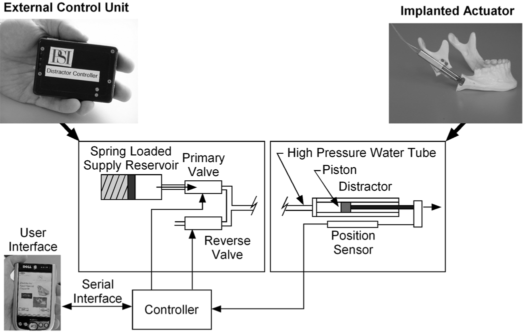
Physical Sciences Inc., the Department of Oral and Maxillofacial Surgery at the Massachusetts General Hospital, and Embedded Systems Design Inc. have collaborated to develop and test a new automated distractor (Fig. 1). The system consists of an implanted actuator, an external control unit to be worn by the patient, and a clinician’s user interface for programming the controller and checking progress during post-operative office visits. Innovative use of microdispensing valve technology, a compact high-pressure pump, embedded control, and miniature position sensors have enabled the development of this advanced automated implant.
Figure 1.
Configuration of new automated distractor
Another advantage of our design is its ability to distract along curved trajectories. In some cases, the bone segment must be added in a trajectory that is not a simple line. This is sometimes accomplished with multiple linear segments, but distraction along a curvilinear trajectory provides a better solution [14]. Most commercially-available (manual) distractors are not capable of curvilinear motion.
In this paper we describe a new approach to automating distraction and provide specifics of the design. A set of live-animal experiments is presented to demonstrate feasibility of the design approach, to assess performance of this specific design in vivo, and to identify key engineering challenges to be addressed in further product development.
Survey of Other Automated Distractors
In the past there have been several efforts to automate the distraction process. These automated distractors fall into two classes: Motor-driven battery powered devices [14,15] and hydraulically-actuated devices [10,11,16–18].
Motor-driven devices have been successfully demonstrated in both live sheep and Gottingen minipigs. They consist of an electric motor driving a conventional screw-type actuator. In some of the motor-driven devices, the controller and batteries were also implanted, though this is not always practical because it requires an additional implant site and it makes changing the treatment course difficult.
Hydraulically-actuated devices consist of two components: An implanted actuator and a control unit consisting of the hydraulic supply (reservoir or pump) and the associated control electronics. The implanted actuator can be simple and compact, so that motors and other components presenting biocompatibility risks do not need to be implanted. Hydraulic actuators can be designed with high force density, so a small actuator can produce sufficient distraction forces. The hydraulic devices, including the one described in this paper, place the control outside the body, providing treatment flexibility and making the controller easy to service, though it is less convenient for the patient to wear.
Kessler, et al. [10,11], demonstrated a reservoir-supplied open-loop hydraulic device in pigs. Ayoub et al. [17–19] successfully demonstrated a hydraulic actuator based on a battery-powered syringe pump. It was tested in 11 sheep [17,18], and later used successfully to correct mandibular asymmetry in a 65 year old man [19].
All of the hydraulic devices described prior to this paper used batteries to power the hydraulic pump, which makes the external control unit large and heavy. The spring-driven pump we describe is small, yet capable of producing higher fluid pressures than achieved previously – an important advantage of the new design because it allows a smaller implanted hydraulic cylinder to be used.
While these devices have provided useful information about the benefits of continuous distraction, a small, convenient, easy-to-use device suitable for routine use in humans has not yet been produced. In addition to providing automated continuous motion, is it desirable to have a device with precise control over the motion, software to alert patients of problems, and the ability to execute curved trajectories. The initial development of such a device is documented in this report.
METHOD OF APPROACH
Design Details
Implanted Actuator
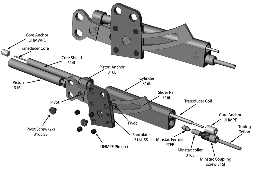
The implanted actuator, shown in Fig. 2, consists of 4 major sub-assemblies: Actuator body, Piston assembly, Slider rail, and Footplate. The implant is attached to the mandible by four bicortical screws (thru two guide holes each in the slider and the footplate).
Figure 2.
Implanted distraction device
The force of motion is produced by the hydraulic piston. The piston has a 4 mm bore, and with a supply pressure between 2.0 MPa (300 psig) and 3.4 MPa (500 psig) produces 25–40 N of actuation force. The piston assembly includes the piston and its seal and the core and core shield, all pressed into the piston anchor. The piston slides inside the actuator body, which also houses the sensor coil.
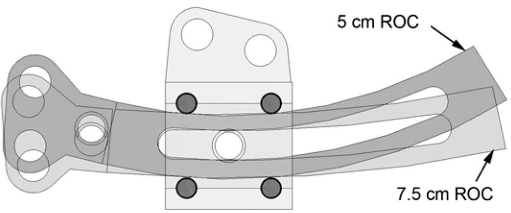
The rail slides on four 1.5 mm diameter ultra-high-molecular-weight-polyethylene (UHMWPE) pins press-fit into the footplate, with the curvature of the slider rail determining the radius of curvature for the distraction (Fig. 3). We envision a kit containing several rails that can be chosen by the surgeon to match each patient. Ritter et al. [14] showed that a finite set of radii of curvature (3,5,7,10 cm and linear) are sufficient to cover curved distraction applications for most humans.
Figure 3.
Rail is supported on four pins
Materials of construction were chosen from among widely-used implant materials known to be biocompatible. The rail and guide, machine screws, distractor body, and piston were all made of 316L stainless steel. The bearing pins and the centering plug for the sensor core (see below) were UHMWPE. The piston o-ring seal was silicone and lubricated with sterile surgical lubricant.
Hydraulic System
The implanted actuator extends when pressurized sterile water is forced into the cylinder. The hydraulic control system, located in the external control box, pressurizes the water and regulates its flow into the piston (See the schematic, Fig. 1). The water is contained in a piston loaded by a spring, designated the reservoir/pump. The supply pressure varies from 3.4 MPa (500 psig) at full spring compression to 2.0 MPa (300 psig) at full spring extension. The reservoir contains 160% of the fluid needed for a 25 mm distraction providing margin for reverse motion. The device has been bench-tested at rates in excess of 10 mm/day, though clinical use will probably not require operation faster than 3 mm/day.
One advantage of the spring-loaded approach is to allow working pressures greater than might be practically provided by an electrically-powered pump. A key advantage of our design is that it allows high fluid pressures to be generated in a small volume, so that both the implanted and external components are smaller than systems developed previously[9,10,17–19].
Motion of the actuator is controlled by a pair of microdispensing solenoid valves (The Lee Co., Westbrook, CT). These compact, high pressure/small orifice valves are an enabling technology for our hydraulic distractor. They allow operation at high fluid pressures, but restrict flow rates so that very low mean distraction rates can be achieved.
At pre-selected intervals (typically 15 minutes) a valve is opened for a period between 100 us and 10 ms, allowing motion in the direction required to reach the desired position. Reverse motion is accomplished by allowing flow out of the actuator. Reversing requires that the actuator is under a compressive axial load – generally true after approximately 2 mm of distraction. Both valves operate at 12 VDC and drawn 500 mW when active. The valves are typically active less than 10 ms/hour.
Position Sensor
The position sensor was a single-coil variable-inductance device consisting of a copper coil (potted in biocompatible epoxy) surrounding a high-magnetic-permeability core (Fig. 4). The core was attached to the piston anchor, and the coil to the distractor body. As the distractor extends, the core moves out of the coil, reducing the sensor inductance.
Figure 4.
Position sensor manufactured by Microstrain Inc. (Burlington, VT)
Two versions of the sensor coil were used: A commercial coil from Microstrain Inc. (Burlington, VT) and a custom coil manufactured by PSI. The Microstrain sensor had a resistance of 62 ohms and an inductance ranging from 4–15 µH over the distractor range of motion. Since the resistance of copper varies with temperature (0.36%/C) and no data was available on temperature variation in the superficial tissues covering the mandible, we chose to develop a measurement circuit that measured both sensor resistance and inductance allowing for accurate position measurements across a range of temperatures. As was discovered during the live animal trials, discussed later, the small gauge wire in the Microstrain coil is subject to both in vivo metal fatigue and corrosion, and the epoxy encapsulating the wire is prone to fatigue cracking. In an attempt to enhance the robustness of the sensor, PSI wound and implanted a coil with larger diameter wire.
Electronic Controller
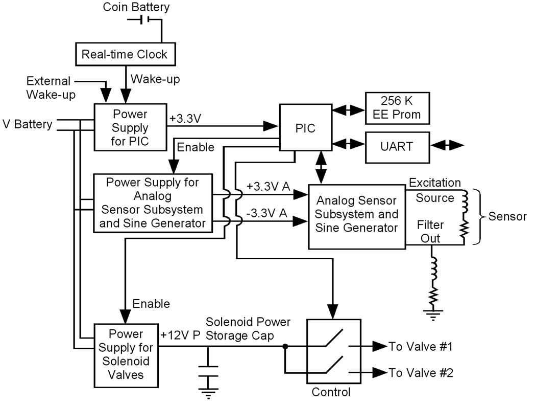
Figure 5 contains a block diagram of the electronic control unit that measures the sensor displacement, calculates any required valve opening, and fires the control valves. The control unit consist of a real time clock, a PIC microcontroller (DSPIC30F6012A, Microchip), a sensor measurement circuit, a solenoid control circuit, a 3.3 volt power supply, a 12 V power supply, and a UART serial interface which allows communication with the user interface.
Figure 5.
Control circuit block diagram
To maximize battery life, the five independent power domains in the system are enabled individually only when needed. Usually, only the real-time clock chip powered by the coin cell is active (expected battery life is 4 years). The real-time clock wakes the PIC every minute, at which time the PIC determines if a control cycle is scheduled. If a control cycle is not scheduled, the PIC returns to sleep. In the event that a control cycle is scheduled, the PIC enables the +/− 3.3V power supplies for the analog measurement subsystem and sine wave generator and measures the sensor position. If the position measurement indicates that a valve needs to be fired, the PIC enables the 12V power supply that slowly charges (typically 12 s) the valve power storage capacitor. A storage capacitor is used to enhance battery life by limiting the peak current draws on the battery. The controller slowly builds charge in a capacitor, and discharges it in the 500mW impulse of power required to fire the valve. The valve current is switched with an NPN high current transistor, and a timer on the PIC controls the valve open time.
As shown in Fig. 5, the inductive sensor is placed in series with an additional inductor/resistor combination, forming a passive first-order low-pass filter. The circuit provides variable-frequency inputs to the filter and provides an RMS filter output to the A/D input on the PIC. The position measurement circuit excites the sensor sequentially at six frequencies (1KHz, 10KHz, 20KHz, 30KHz, 50KHz, 70KHz, and 90KHz). Using measurements of both the gain and cutoff frequency, we calculate both the resistance and inductance of the sensor. We then calculate the distractor displacement based upon the inductance.
Control Algorithm
The frequency of control cycle execution is set by the user but a default period of 15 minutes was used for most trials. Assuming a 1 mm/day distraction rate, this results in a distraction step size of 10 µm which is the nominal sensor resolution. Thus, every 15th wake-up event, the control algorithm is executed. The control steps are as follows. First, the distractor displacement is measured. Next, based on the start time, initial position, and rate of distraction, the controller computes the desired position (the distraction profile is linear). At each control cycle, the error between the desired and actual position is computed, and a proportional+integral (PI) control law is used to calculate pulse width. (typical pulses are 1–3 ms). If the commanded pulse width is less than 100 µs, the valves are not fired to conserve power. The sign of the error determines which valve is fired.
Finally, the control algorithm performs an error check before firing a valve. For example, if the measured position is outside of range, or if there is an error computing the inductance (e.g., a negative inductance value), the controller assumes a failed sensor measurement and does not operate a valve.
User Interface
The control unit is programmed through a graphical user interface implemented on a Dell PocketPC™. Communication between the PocketPC and the controller is done through the serial interface. Through the user interface changes can be made to any of the calibration parameters including control gains, control limits, and distraction rates. In addition, commands can be sent to directly fire the valves, measure position, check for errors, monitor battery levels, or download and view the data log.
Demonstration Tests
To demonstrate feasibility of the design approach, to assess the performance of this specific design in vivo, and to identify key engineering challenges, we conducted a series of demonstration tests. The distractor was first tested on the bench. Next, a distractor was implanted and test activated in a pig cadaver head. Finally, the distractor was tested in five live pigs, as described below in detail. An additional 11-day test in a pig cadaver, between the third and fourth live-animal tests, was used to test engineering upgrades to the device.
The demonstration experiments assessed ease of implant, mechanical durability, adequacy of distraction force, controller performance (tracking of desired trajectory), and user interface operability. Bone quality was assessed through histological analysis and, as this analysis is the subject of a separate paper, will not be discussed further here. We focus this paper on the operation of the device itself.
Live Animal Test Procedures
The prototype distractor was tested in Yucatan minipigs, a breed used previously by Troulis et al. for DO research with manual distraction devices [20]. All animal tests were conducted in the animal research facilities at the Massachusetts General Hospital (MGH) in Boston, MA. The pigs were all females between 25 and 30 kg, and approximately 6 months old. A few days prior to the procedure, the jacket that would hold the controller was placed on the animal. The animals were fed a soft-food diet throughout the test. They received antibiotics and analgesics for seven days after surgery.
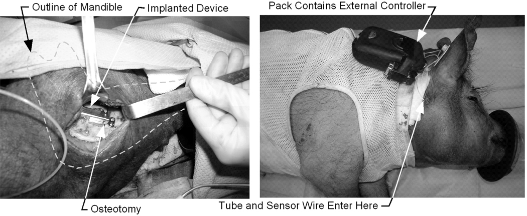
Prior to surgery, the implanted components of the device were sterilized in autoclave instrument bags at 121C for 10 minutes. Figure 6 shows the surgical procedure. An incision is made to access the inferior border of the mandible and the masseter muscle is detached. The line for the osteotomy is drawn in pencil on the bone. Pilot holes for the screws are drilled using the distractor as a guide. The osteotomy is made along the marked line with a reciprocating saw and completed with an osteotome. When the wire and tube are appropriately placed, the distractor is attached to the bone with the four bicortical screws. Once installed, the device is activated using the manual controls on the user interface, and then reversed to the fully-closed position. Radiographs (x-rays) were taken immediately before and after the implant procedure, and on days 7 and 12 (middle and end of the distraction phase), and on day 36 (end of consolidation).
Figure 6.
Surgical procedure: (a) Device implanted on mandible, (b) External controller attached to back of animal
RESULTS
The results for each animal are summarized in Table 1. Though all tests began with closed-loop position control in the days after surgery, due to sensor failure all ended under open-loop control. Open-loop control was achieved by fixing the commanded pulse width.
Table 1.
Summary of Results from Animal Tests of Distractor
| Animal | Final Distraction Distance |
Complications |
|---|---|---|
| 1 | 11mm | Sensor wire broken; minor software problems |
| 2 | 5.6mm | Valve leak due to debris; sensor epoxy/seal failed |
| 3 | Not Completed | First device damaged/replaced; second device - sensor epoxy/seal failed, water leak at actuator |
| 4 | 9mm | Sensor epoxy/seal failed; infection in Bone |
| 5 | 9mm (Reduced to 7mm) |
Sensor epoxy/seal failed; another animal chewed through tube, allowing 2 mm of reverse motion (to 7 mm) |
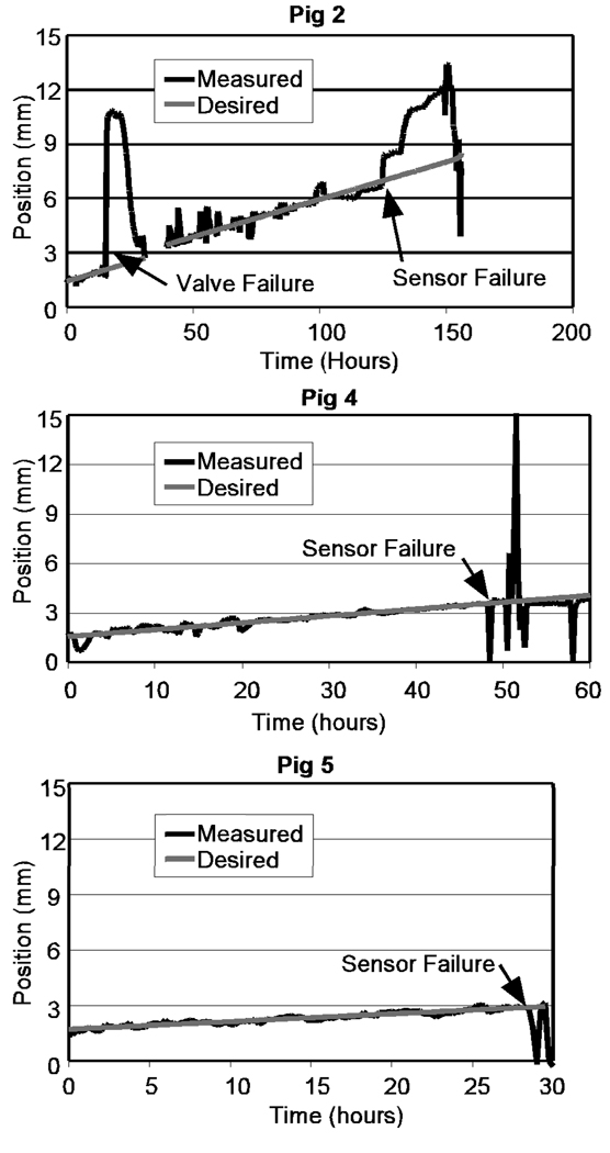
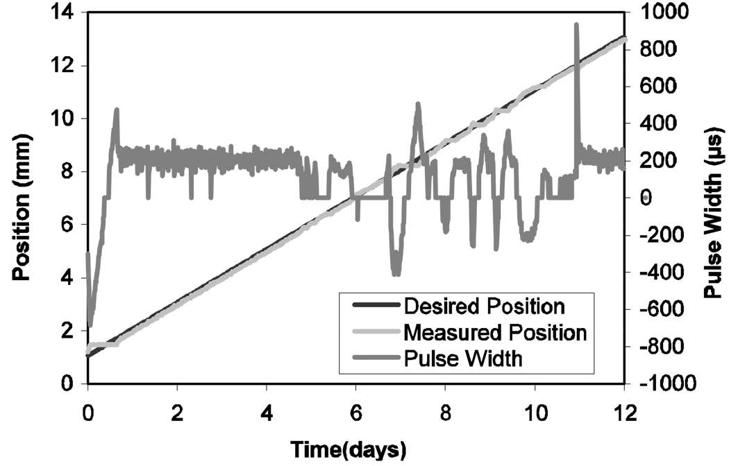
In Fig. 7, which shows the tracking performance for three of the pigs, the onset of sensor failure is indicated. The final position for each animal (Table 1) was determined by measuring (with calipers) the extension of the distractor at sacrifice. Intermediate positions were obtained from the periodic radiographs. Figure 8 shows the control tracking performance for the cadaver test.
Figure 7.
Tracking performance for Animals 2, 4, and 5
Figure 8.
Tracking performance in cadaver head, with valve pulse period shown. Negative pulse widths correspond to firing the reversing valve
Animal 1
Problems in the first animal were mainly associated with the position sensor, though some minor software problems were identified and corrected with this animal. The wire was damaged (and repaired) at the end of the implant procedure. It was severed and repaired on day two, and the animal finally pulled the wire out of the sensor on day 4, catching it on the water spigot in its cage. With the sensor output disabled, the distraction was completed under open-loop control by setting a fixed pulse width (2 ms).
Animal 2
In response to the sensor wire damage observed in Animal 1, the distractor implanted in Animal 2 reinforced the sensor wire by placing it in a PTFE sheath. Several hours after implant, the forward valve failed to seal due to debris shed from tapped threads in the plastic fluid fittings (note: the controller reacted properly and reversed the motion, Fig. 7). The valve assembly was removed from the external controller and repaired. The device operated properly for a three days until the sensor failed, when corrosion of the copper coil wires by blood caused an open sensor circuit. Later analysis found cracks in the epoxy sealing the coil which allowed blood to penetrate the coil. This animal was completed under open-loop control with 2.5 ms pulses. The bone on the upper side of the gap consolidated prematurely, preventing full distraction.
Animal 3
Upon waking from anesthesia the animal became rambunctious in its cage. It pulled both the hydraulic tube and sensor wire out of the implanted actuator. Surgery was repeated three days later to implant a new device with an enhanced epoxy seal on the sensor coil. This enhanced seal failed to prevent blood induced corrosion, leading to an open circuit sensor failure. Several days later, the seal between the actuator and hydraulic tube loosened and leaked. As this joint is inaccessible without additional surgery, the experiment was terminated.
Cadaver Test
In an effort to remedy the failure of the epoxy in the sensor, PSI worked with engineers at Microstrain to produce a sensor with a more reliable epoxy seal. Once the third of the live animals was sacrificed, the head was removed. The device was installed on the left side of the mandible (the side opposite the original distraction) and programmed for 1 mm/day distraction. The head remained un-refrigerated for 11 days while the distractor operated. Porcine blood was injected into the incision twice during the tests to simulate the effect of blood on the device. Figure 8 shows the results of this test. The tracking performance is excellent, with a maximum error of 0.470 mm and an RMS error of 0.086 mm. The corresponding valve opening times are also shown.
Animal 4
In preparation for the fourth animal test, a filter was inserted into the hydraulic passage upstream of the valves to prevent valve fouling, and no further debris problems occurred. In spite of the success in the cadaver test, the sensor failed in animal 4 after two days. Distraction was completed under open loop control.
Animal 5
In the final animal, we tested a different sensor which was fabricated with larger wire. The sensor failed after two days, but has provided us with a design path for a robust sensor. Animal 5 reached a distraction distance of 9 mm under open-loop control. However the distraction reversed to 7 mm when an animal in an adjacent cage chewed through the hydraulic tube.
DISCUSSION
The surgical implant procedure was accomplished without complications in all five animals and all of the devices functioned for some period of time in each animal. Damage by the animals or the implant environment led to eventual sensor failures in all five cases, but each time we made design improvements to address the failures. Distraction was completed under open-loop control in four of the five animals, though only one ended close to the desired distraction of 12 mm.
The only consistent failure of the devices in the live animals was the position sensor. Despite several attempts to strengthen the cable, we consistently found that flexing of the wires as the animal moved its mouth caused cracking of the epoxy at the end of the sensor, which permitted blood to enter the sensor and corrode the wires. The sensor did not fail in the cadaver test, though blood was injected at the site, which led to the conclusion that the epoxy cracks are due to motion of the cables as the animal moves its jaw. PSI eventually developed a process for making its own sensor coils. The next stage of development will focus on making the sensors robust to the implant environment by replacing the epoxy with a flexible sealing compound to allow some movement without cracking the seal.
Completing the distractions even without the sensors (e.g., without closed-loop control) was valuable because it provided information about the implant for durability and adequacy of distraction force, as well as the external hardware and user interface. The mechanical components of the implanted hardware survived without damage in all of the animals, indicating that they are sufficiently strong. They are structurally similar to currently –marketed devices, and we do not believe changes to the track, guides, or cylinder are needed.
While the closed-loop controller was operating, tracking performance was very good. For example in the Cadaver, tracking errors were below 86 µm after the initial start-up transient period. There is no accepted requirement for the tracking performance, but clinical outcomes are considered good if the final distance is within 1 mm of the desired length. In Fig. 7, errors during proper operation in the live animals are below 1mm. This performance result shows sufficiency of the hydraulic system as well as the PI control law.
The distraction force was judged to be adequate over the distance range tested. The distraction of the cadaver mandible to 11 mm requires more force than a similar process in live animals because the surrounding tissue is stiffer and does not grow to accommodate expansion. These observations are consistent with prior work by others [10] have shown that distraction forces are below 30N.
There was occasional damage to the external components (e.g., loose wires or batteries). Padding inside the controller box remedied this, though the next generation control box will be designed to better support and protect the components it contains.
The user interface software performed well, but as configured is more complex than a clinician would want or need. Furthermore, we found the WindowsCE platform to be unstable requiring frequent restart of the PocketPC. We are planning a small, dedicated, hand-held user interface that will be less expensive and easier to use. Because commands are transmitted serially, the user interface software that generates the commands and the controller software that receives them can be independently upgraded as long as the same command structure is used.
Premature consolidation of the bone was a problem in two of the animals (2 and 4), and led to stalling of the device before the full desired distance was reached. This will be remedied with a change to the distraction protocol. With a 1mm/day rate of motion the distraction on the inside of the curve is only about 0.5 mm/day, which sometimes causes consolidation even in discrete distraction. Continuous curvilinear distraction will need to be faster for a small radius of curvature if large expansions are performed.
CONCLUSIONS AND FUTURE WORK
We have developed an automated device for distraction osteogenesis of the mandible. The test sequence was largely successful, achieving the several milestones necessary to validate the overall design approach. The important achievements of these experiments included:
Demonstration that the device design can withstand the loads associated with the distraction protocol
Demonstration that the actuator can provide the forces necessary for distraction
Demonstration that closed-loop control approach can expand the gap at prescribed rates in the presence of real dynamic load conditions.
In addition, the tests helped to identify the items that require attention in the next phase of engineering development, such as the sensor and user interface. Obviously the most significant engineering challenge that must be overcome is the development of a more robust sensor. We intend to modify the larger-wire-gauge sensor by incorporating a flexible potting compound (e.g., silicone) in place of the epoxy. This flexible seal will allow for flexing of the wires without cracking the sealant.
ACKNOWLEDGEMENTS
This work was funded by a Phase II SBIR grant (5R44DE014803-03) from the NIH/NIDCR. The work was also supported in part by the MGH Department of Oral and Maxillofacial Education and Research Fund. The authors wish to thank Dr. Edward Seldin (MGH Department of OMFS) who was the first to conceptualize the importance of curvilinear distraction and to thank Synthes Maxillofacial for helpful discussions regarding distractor design and for assistance in machining necessary to use Synthes locking screws with our prototype distractors.
Contributor Information
Marten F. Byl, Email: byl@psicorp.com.
Batya Goldwaser, Email: bgoldwaser@partners.org.
Maria Papadaki, Email: mpapadaki@partners.org.
Roger Kromann, Email: rkromann@esdnet.com.
Brent Yates, Email: byates@esdnet.com.
Joseph R. Morency, Email: morency@psicorp.com.
Leonard B. Kaban, Email: lkaban@partners.org.
Maria J. Troulis, Email: mtroulis@partners.org.
REFERENCES
- 1.Codivilla A. On the Means of Lengthening, in the Lower Limbs, the Muscles and Tissues Which Are Shortened Through Deformity. Am. J. Orthop. Surg. 1905;2:353. doi: 10.1007/s11999-008-0518-7. [DOI] [PMC free article] [PubMed] [Google Scholar]
- 2.Ilizarov GA. The Tension-stress Effect on the Genesis and Growth of Tissues: Part II. The Influence of Rate and Frequency of Distraction. Clin. Orthop. Rel. Res. 1989;239:263. [PubMed] [Google Scholar]
- 3.Ilizarov GA. The Tension-stress Effect on the Genesis and Growth of Tissues: Part I. The Influence of Stability of Fixation and Soft-tissue Preservation. 1989;238:249–281. [PubMed] [Google Scholar]
- 4.McCarthy JG, Schreiber J, Karp N, et al. Lengthening of the Human Mandible by Gradual Distraction. Plast. Reconstr. Surg. 1992;89:1. [PubMed] [Google Scholar]
- 5.Perrott DH, Berger R, Vargervik K, Kaban LB. Use of Skeletal Distraction Device to Widen the Mandible: A Case Report. J. Oral. Maxillofac. Surg. 1993;51:435. doi: 10.1016/s0278-2391(10)80364-7. [DOI] [PubMed] [Google Scholar]
- 6.Kaban LB, Troulis MJ, editors. Pediatric Oral and Maxillofacial Surgery. Philadelphia: Saunders; 2004. [Google Scholar]
- 7.Maull DJ. Review of Devices for Distraction Osteogenesis of the Craniofacial Complex. Seminars in Orthodontics. 1999;5(1):64–73. doi: 10.1016/s1073-8746(99)80045-0. [DOI] [PubMed] [Google Scholar]
- 8.Troulis MJ, Kaban LB. Complications of Mandibular Distraction Osteogenesis. Oral & Maxillofac. Surg. Clin. N. America. 2003;15:251–264. doi: 10.1016/S1042-3699(02)00101-2. [DOI] [PubMed] [Google Scholar]
- 9.Kessler P, Neukam FW, Wiltfang J. Effects of Distraction Forces and Frequency of Distraction on Bony Regeneration. British J. Oral and Maxillofacial Surgery. 2005;43:392–398. doi: 10.1016/j.bjoms.2004.10.015. [DOI] [PubMed] [Google Scholar]
- 10.Kessler P, Wiltfang J, Neukam FW. A New Distraction Device to Compare Continuous and Discontinuous Bone Distraction in Mini-pigs: A Preliminary Report. J. Craniomaxillofac. Surg. 2000;28:5–11. doi: 10.1054/jcms.2000.0101. [DOI] [PubMed] [Google Scholar]
- 11.Wiltfang J, Kessler P, Merten H-A, Neukam FW. Continuous and Intermittent Bone Distraction Using a Microhydraulic Cylinder: An Experimental Study in Minipigs. Br. J. Oral Maxillofac. Surg. 2001;39:2–7. doi: 10.1054/bjom.2000.0564. [DOI] [PubMed] [Google Scholar]
- 12.Troulis MJ, Glowacki J, Perrott DH, Kaban LB. The Effects of Latency and Rate on Distraction Osteogenesis of the Porcine Mandible. J Oral Maxillofac Surg. 2000;58:507–513. doi: 10.1016/s0278-2391(00)90012-0. [DOI] [PubMed] [Google Scholar]
- 13.Tavakoli K, Walsh WR, Bonar F, Smart R, Wulf S, Poole MD. The Role of Latency in Mandibular Osteodistraction. J. Craniomaxillofacial Surgery. 1998;26:209–219. doi: 10.1016/s1010-5182(98)80016-4. [DOI] [PubMed] [Google Scholar]
- 14.Ritter L, Yeshwant K, Seldin EB, Kaban LB, Gateno J, Keeve E, Kikinis R, Troulis MJ. Range of Curvilinear Distraction Devices Required for Treatment of Mandibular Deformities. J Oral Maxillofac Surg. 2006;64(2):259–264. doi: 10.1016/j.joms.2005.10.015. [DOI] [PubMed] [Google Scholar]
- 15.Schmelzeisen R, Neumann G, von der Fecht R. Distraction Osteogenesis in the Mandible with a Motor-driven Plate: A Preliminary Animal Study. Br. J. Oral Maxillofac. Surg. 1996;34:375–378. doi: 10.1016/s0266-4356(96)90090-x. [DOI] [PubMed] [Google Scholar]
- 16.Ploder O, Mayr W, Schnetz G, et al. Mandibular Lengthening with an Implanted Motor-driven Device: Preliminary Study in Sheep. Br. J. Oral Maxillofac. Surg. 1999;37:273–276. doi: 10.1054/bjom.1999.0115. [DOI] [PubMed] [Google Scholar]
- 17.Ayoub AF, Richardson W. A New Device for Microincremental Automatic Distraction Osteogenesis. Br. J. Oral Maxillofac. Surg. 2001;39:353–355. doi: 10.1054/bjom.2000.0659. [DOI] [PubMed] [Google Scholar]
- 18.Ayoub AF, Richardson W, Koppel D, et al. Segmental Mandibular Reconstruction by Microincremental Automatic Distraction Osteogenesis: An Animal Study. Br. J. Oral Maxillofac. Surg. 2001;39:356–364. doi: 10.1054/bjom.2001.0658. [DOI] [PubMed] [Google Scholar]
- 19.Ayoub AF, Richardson W, Barbenel JC. Mandibular Elongation by Automatic Distraction Osteogenesis: The First Application in Humans. Br. J. Oral Maxillofac. Surg. 2005;43(4):324–328. doi: 10.1016/j.bjoms.2005.02.008. [DOI] [PubMed] [Google Scholar]
- 20.Troulis MJ, Glowacki J, Perrott DH, et al. Distraction Osteogenesis in a Procine Mandible; American Association of Oral and Maxillofacial Surgeons 80th Annual Meeting; New Orleans, LA. 1998. [Google Scholar]


