Abstract
A liquid nitrogen (LN2) cooled dual-channel array coil was designed and built for use on a 3.0-T whole-body scanner. In vivo imaging of a volunteer's fingers and imaging of a deceased mouse and oil phantom were performed using the LN2 cooled array and a similar room-temperature coil. Imaging results showed that the LN2 cooled array provides a signal-to-noise ratio gain of up to 240% as compared with its room-temperature counterpart. LN2 cooled arrays may be useful for high-resolution clinical imaging of joints, skin, eyes and peripheral vessels as well as for biomedical imaging of small animals in human disease modeling.
Keywords: Magnetic resonance imaging, Cryogenic RF coil, Phased array coil, High-resolution imaging
1. Introduction
Cryogenic radiofrequency (RF) receiver coils have been developed to improve signal-to-noise ratio (SNR) in MRI and spectroscop y [1]. The y include copper coils cooled to liquid nitrogen (LN2) temperature (77 K) [1-6] or to liquid helium temperat ure (4.2 K) [7,8] and high-temperature superconducting (HTS) coils [9-12]. Cryogenic cooling reduces RF coil noise through the lowering of coil resistance (RC) and coil temperature. For an unloaded coil with inductance L, RC can be calculated from the unloaded Q-factor (QU) using
Meanwhile, the sample resistance (RS), corresponding to the sample noise voltage, can be obtained from the loaded coil Q-factor (QL) as
Total noise equals coil noise plus sample noise. Under the condition that sample noise does not dominate the total noise, the SNR increases when the RF coil is cooled from room temperature (300 K) to LN2 temperature (77 K). The SNR gain is given by the following equations [1,2]:
where SNRL and SNRR are SNRs obtained from the LN2 cooled coil and room-temperature coil, respectively; TR and TL are the room temperature and LN2 temperature, respectively; RCR and RCL are the coil resistance at room temperature and LN2 temperature, respectively; QU300 and QU77 are the unloaded Q-factors at room temperature and LN2 temperature, respectively; and is the sample Q-factor.
In theory, if sample noise is much lower than RF coil noise, then the SNR gains by a factor of 2.8 when cooled to LN2 temperature [2]. An in vivo imaging study using LN2 cooled copper RF coils at 1.5 T obtained an SNR gain of 2.7-fold [2]. However, sample noise increases faster than coil noise with higher resonance frequency and larger coil size. Coils are restricted to a few centimeters in size to keep sample noise significantly lower than coil noise at 1.5 T or higher fields [1,2,6]. This limitation in coil size leads to the development of LN2 cooled phased array coils that provide larger field-of-view (FOV) coverage while maintaining the SNR of small coil elements [6,13]. Recently, with the availability of well-developed 3-T whole-body MRI systems, 3-T imaging is becoming widely used for both clinical and research purposes. Since there has been no report on the feasibility of LN2 cooled coils at 3 T, it was our objective to design, construct as well as test an LN2 cooled phased array coil at 3 T and evaluate whether it provides SNR advantage over a similar room-temperature coil despite higher sample noise at 3 T than at lower field strength.
2. Materials and methods
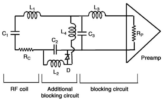
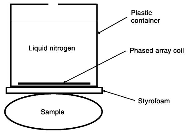
The study was conducted with a Siemens Trio 3.0-T whole-body MR scanner. Two similar dual-channel array coils were developed. They have the same physical dimensions but were separately tuned to 123.20 MHz and matched to 50 Ω at room temperature and LN2 temperature. The two coil elements in each array were constructed using 14-G copper wire, formed into a rounded square shape and mounted side by side on a printed circuit board that does not deform at LN2 temperature. The size of each coil element is 3.5 × 3.5 cm2. Decoupling among the coil elements was achieved through partial overlapping of the elements [13]. Initial testing showed image artifacts related to RF coupling between the transmit coil and the coil elements in the LN2 cooled coil; a more effective RF decoupling design [13,14] was implemented on the LN2 cooled coil (Fig. 1). The decoupling circuit normally used in phased array coils [13] is not effective since the impedance of the output capacitor becomes comparable with the input impedance of the preamplifier in the LN2 cooled coil. A second decoupling circuit activated during RF transmission was added to overcome this [14]. Each array was placed inside a plastic container able to hold LN2 (Fig. 2). A 2-mm-thick Styrofoam was used to provide thermal insulation for the object scanned using the LN2 cooled array. The separation between the coil arrays and the scanned object was about 1 cm.
Fig. 1.
Circuit diagram of a coil element in the LN2 cooled phased array. RC, L1, C1, C2 and C3 comprise the RF coil tuning and matching circuitry. L3 and C3 are the regular blocking circuits used in phased array coils. L2, C2, L4 and D form an additional blocking circuitry activated during RF transmission. L4 is a choke. This additional blocking circuitry is needed since the C3 value increases significantly in LN2 cooled coil, lowering its associated impedance to a value comparable with RP. This reduces the parallel resonance impedance as well as the current-blocking ability of the L3 – C3 circuit and allows coupling between the coil element and the RF transmission coil that can cause B1 inhomogeneity image artifacts.
Fig. 2.
Experimental setup in the imaging tests. Both LN2 cooled and room-temperature array coils were tested using similar setups except that no LN2 was used for the room-temperature array coil.
The imaging properties of the phased array coils were tested using in vivo, animal and phantom studies. In vivo imaging studies were conducted on a healthy volunteer whose fingers were placed under the array coils during scans. Written informed consent was obtained from the volunteer, and the study was approved by the research subject review board of our institution. A deceased adult mouse was also imaged using the array coils. In addition, a phantom made of vegetable oil with negligible sample noise was imaged to evaluate the maximum achievable SNR gain of the LN2 cooled array. For every study, the LN2 cooled and the room-temperature array coils were tested consecutively under identical scanner settings, including RF transmission and receiver gains, to enable quantitative comparison of the results of the two types of coils. SNRs were then obtained from the acquired images by dividing the averaged signal intensities measured at several regions of interest (ROIs) inside the object by the background standard deviation. The phantom was scanned twice using TR values of 500 and 2000 ms to verify that the SNR gain obtained from the LN2 cooled array was not caused by T1 shortening due to the cooling effect. The SNR gains obtained using the two TR values were then noted for any significant difference.
3. Results
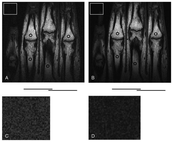
The image data showed a significant SNR gain in the LN2 cooled array over the room-temperature array. The average SNR gains, as measured from the multiple ROIs, are 214% for the fingers (Fig. 3), 209% for the mouse (Fig. 4) and 240% for the oil phantom. The ratio of SNR (TR=2000) to SNR (TR=500) is the same for both the LN2 cooled array and the room-temperature array, indicating that the SNR gain in the LN2 cooled array is not due to a T1 change in the phantom.
Fig. 3.
In vivo spin-echo images of fingers obtained using (A) the room-temperature array and (B) the LN2 cooled array. Imaging parameters were as follows: TR/TE = 1000 ms/15 ms; FOV= 10 cm; slice thickness = 1 mm; matrix size = 512 × 384; and scan time = 6 min 24 s. The circles indicate the ROIs for signal intensity measurements, whereas the bars underneath show the position of individual coil elements. The squares in Panels (A) and (B) represent background regions that are enlarged and displayed with increased contrast in Panels (C) and (D) to highlight the noise level difference between the two finger images.
Fig. 4.
Mouse spin-echo images obtained using (A) the room-temperature array and (B) the LN2 cooled array. The imaging parameters were as follows: TR/TE = 500 ms/13 ms; FOV= 10 cm; slice thickness = 1 mm; matrix size = 256 × 256; and scan time = 2 min 8 s. The circles indicate the ROIs for signal intensity measurements, whereas the bars underneath show the position of individual coil elements.
4. Discussion
In this study, we designed, built and tested an LN2 cooled phased array coil for 3.0 T. The image data showed that it provides SNR gains of up to 240% as compared with its room-temperature counterpart. Our SNR gains did not reach the theoretical value of 280% due to noises from the preamplifier, cable and sample. In addition, nonmagnetic chip capacitors of relatively high values (in the order of 100 pF) have to be used for coil tuning and matching in the LN2 cooled coil. Their Q-factors are relatively low (in hundreds) at 123 MH z (Table 1) and can affect the overall Q-factor of the LN2 cooled coil.
Table 1.
Typical Q-factors of nonmagnetic chip capacitors used in RF coils
| Capacitance (pF) | Frequency (MHz) |
|||
|---|---|---|---|---|
| 30 | 60 | 90 | 120 | |
| 1 | 44,500 | 23,300 | 15,400 | 11,300 |
| 10 | 21,100 | 8700 | 5000 | 3400 |
| 56 | 5800 | 2100 | 1100 | 743 |
| 100 | 3400 | 1200 | 653 | 428 |
| 220 | 1600 | 559 | 305 | 201 |
Data were obtained from Voltronics (Denville, NJ, USA).
The SNR gain indicates that sample noise does not dominate the total noise in our LN2 cooled coil despite its increased value at 3 T. Combined with phased array construction, the LN2 cooled coil expands its FOV coverage to beyond that of individual coil elements and increases its potential applications and usefulness. LN2 cooled array coils should provide tremendous benefits to high-resolution imaging. As SNR varies as the square root of the number of signal averages, a twofold SNR gain translates to a fourfold reduction in the number of signal averaging and scan time. Since SNR increases approximately linearly with field strength that is in the order of 1 T [15], LN2 cooled array at 3 T provides an SNR similar to that of a room-temperature array at 6–7 T but without issues associated with higher-field MRI, such as much more expensive scanners and higher RF power depositions that increase as the square of field strength. Although small bore MR systems can provide a high magnetic field with a lower system cost, they allow only limited FOVs and are usually not compatible with human in vivo imaging.
Liquid helium cooled RF coils have also been used to improve SNR [7,8]. However, their thermal insulation is much more difficult to design due to the extremely low temperature of liquid helium. Another disadvantage of those is that liquid helium is several times more expensive than LN2. Furthermore, if sample noise is taken into account, liquid helium cooled coils may not provide significant additional SNR gains as compared with LN2 cooled coils.
Compared with HTS coils [9-12], LN2 cooled coils provide the advantages of simpler array construction and flexible three-dimensional shapes for volumetric coverage. Although flexible HTS tapes/wires have also been used for RF coils, their superconducting properties degrade rapidly in a high magnetic field [1]. Besides, the Q-performance of HTS materials depends on static magnetic field orientation, thus limiting HTS coil applications [1]. Furthermore, HTS coil performance is more easily affected by sample loading. A small sample loading, such as one that drops the room-temperature Q-factor by 10%, can bring the SNR gain in HTS coils close to that of LN2 cooled coils [2].
Our future work includes increasing the number of coil elements to provide even larger FOV coverage and combining LN2 cooled array coils with parallel imaging techniques to save imaging time [16,17]. However, as mentioned in Section 2, the conventional RF decoupling technique for phased array coils [13] is not sufficient for LN2 cooled array coils and the inductive coupling among nonneighboring coil elements will degrade coil performance [6]. The additional decoupling circuit used in this study can only be used to decouple coil elements from the transmission coil but not to decouple one coil element from another. One potential way to provide more effective decoupling among coil elements is to use preamplifiers with ultralow input impedance [18]; we are investigating this approach for LN2 cooled array coils. Besides developing the coil itself, we are also designing a clinically compatible LN2 Dewar that will allow longer and safer scanning for subjects. The Dewar design is challenging since it, on one hand, needs to be MRI compatible—thus prohibiting the use of metal— but, on the other hand, has to be very strong to withstand the pressure exerted on the vacuum space for thermal insulation. We are looking into using fiber glass materials for this purpose.
5. Conclusion
We have developed and tested an LN2 cooled dual-channel array coil for 3.0 T. Phantom, in vivo and animal imaging studies showed that the LN2 cooled array has significant SNR gains of over 200% as compared with its room-temperature counterpart. Future potential applications of LN2 cooled arrays include high-resolution clinical imaging of joints, skin, eyes and superficial vessels. LN2 cooled arrays may also be used in MR microscopy of small animals for human pathology modeling, which often demands high coil sensitivity.
Acknowledgments
This work was partially supported by the NIH through Grant No. 5R03AR048949.
References
- 1.Darrasse L, Ginefri JC. Perspectives with cryogenic RF probes in biomedical MRI. Biochimie. 2003;85:915–37. doi: 10.1016/j.biochi.2003.09.016. [DOI] [PubMed] [Google Scholar]
- 2.Wright AC, Song HK, Wehrli FW. In vivo MR micro imaging with conventional radiofrequency coils cooled to 77 degrees K. Magn Reson Med. 2000;43:163–9. doi: 10.1002/(sici)1522-2594(200002)43:2<163::aid-mrm1>3.0.co;2-k. [DOI] [PubMed] [Google Scholar]
- 3.Tacke J, Adam G, Speetzen R, Brucksch K, Bucker A, Heshel I, et al. MR-guided interstitial cryotherapy of the liver with a novel, nitrogen-cooled cryoprobe. Magn Reson Med. 1998;39:354–60. doi: 10.1002/mrm.1910390304. [DOI] [PubMed] [Google Scholar]
- 4.Hall AS, Barnard B, McArthur P, Gilderdale DJ, Young IR, Bydder GM. Investigation of a whole-body receiver coil operating at liquid nitrogen temperatures. Magn Reson Med. 1988;7:230–5. doi: 10.1002/mrm.1910070211. [DOI] [PubMed] [Google Scholar]
- 5.Styles P, Soffe NF. A high-resolution NMR probe in which coil and preamplifier are cooled with liquid-helium. J Magn Reson. 1984;60:397–404. doi: 10.1016/j.jmr.2011.09.002. [DOI] [PubMed] [Google Scholar]
- 6.Kwok WE, You Z, Totterman SM, Zhong J. In vivo MR imaging using liquid nitrogen cooled phased array RF receiver coil at 1.5 T; Book of Abstracts: Tenth Annual Meeting of the International Society of Magnetic Resonance in Medicine; Honolulu, Hawaii. 2002. p. 879. [Google Scholar]
- 7.Reyes AP, Bachman HN, Halperin WP. Versatile 4 K nuclear magnetic resonance probe and cryogenic system for small-bore high-field Bitter magnets. Rev Sci Instrum. 1997;68:2132–7. [Google Scholar]
- 8.Seton HC, Hutchison JMS, Bussell DM. A 4.2 K receiver coil and SQUID amplifier used to improve the SNR of low-field magnetic resonance images of the human arm. Meas Sci Technol. 1997;8:198–207. [Google Scholar]
- 9.Ginefri JC, Darrasse L, Crozat P. High-temperature superconducting surface coil for in vivo microimaging of the human skin. Magn Reson Med. 2001;45:376–82. doi: 10.1002/1522-2594(200103)45:3<376::aid-mrm1049>3.0.co;2-r. [DOI] [PubMed] [Google Scholar]
- 10.Hurlston SE, Brey WW, Suddarth SA, Johnson GA. A high-temperature superconducting Helmholtz probe for microscopy at 9.4 T. Magn Reson Med. 1999;41:1032–8. doi: 10.1002/(sici)1522-2594(199905)41:5<1032::aid-mrm23>3.0.co;2-x. [DOI] [PubMed] [Google Scholar]
- 11.Miller JR, Hurlston SE, Ma QY, et al. Performance of a high-temperature superconducting probe for in vivo microscopy at 2.0 T. Magn Reson Med. 1999;41:72–9. doi: 10.1002/(sici)1522-2594(199901)41:1<72::aid-mrm11>3.0.co;2-a. [DOI] [PubMed] [Google Scholar]
- 12.Wosik J, Wang F, Xie LM, et al. High-T-c superconducting surface coil for 2 Tesla magnetic resonance imaging of small animals. IEEE Trans Appl Supercond. 2001;11:681–4. [Google Scholar]
- 13.Roemer PB, Edelstein WA, Hayes CE, Souza SP, Mueller OM. The NMR phased-array. Magn Reson Med. 1990;16:192–225. doi: 10.1002/mrm.1910160203. [DOI] [PubMed] [Google Scholar]
- 14.Kuhns PL. Inductive coupling and tuning in NMR probes; applications. J Magn Reson. 1988;78:69–76. [Google Scholar]
- 15.Hoult DI, Chen CN, Sank VJ. The field dependence of NMR imaging: II. Arguments concerning an optimal field strength. Magn Reson Med. 1986;3:730–46. doi: 10.1002/mrm.1910030509. [DOI] [PubMed] [Google Scholar]
- 16.Pruessmann KP, Weiger M, Scheidegger MB, Boesiger P. SENSE: sensitivity encoding for fast MRI. Magn Reson Med. 1999;42:952–62. [PubMed] [Google Scholar]
- 17.Sodickson DK, Manning WJ. Simultaneous acquisition of spatial harmonics (SMASH): fast imaging with radiofrequency coil arrays. Magn Reson Med. 1997;38:591–603. doi: 10.1002/mrm.1910380414. [DOI] [PubMed] [Google Scholar]
- 18.de Zwart JA, Ledden PJ, Kellman P, van Gelderen P, Duyn JH. Design of a SENSE-optimized high-sensitivity MRI receiver coil for brain imaging. Magn Reson Med. 2002;47(6):1218–27. doi: 10.1002/mrm.10169. [DOI] [PubMed] [Google Scholar]


