Abstract
A high-throughput screening system for homogeneous catalyst discovery has been developed by integrating a continuous-flow capillary-based microreactor with ultra-high pressure liquid chromatography (UHPLC) for fast online analysis. Reactions are conducted in distinct and stable zones in a flow stream that allows for time and temperature regulation. UHPLC detection at high temperature allows high throughput online determination of substrate, product, and byproduct concentrations. We evaluated the efficacies of a series of soluble acid catalysts for an intramolecular Friedel-Crafts addition into an acyliminium ion intermediate within one day and with minimal material investment. The effects of catalyst loading, reaction time, and reaction temperature were also screened. This system exhibited high reproducibility for high-throughput catalyst screening and allowed several acid catalysts for the reaction to be identified. Major side products from the reactions were determined through off-line mass spectrometric detection. Er(OTf)3, the catalyst that showed optimal efficiency in the screening, was shown to be effective at promoting the cyclization reaction on a preparative scale.
Introduction
Microreactors are attracting increased attention for a variety of synthesis applications because of their superior capacity for heat and mass transfer and their safety benefits in handling potentially explosive or toxic compounds relative to standard batch reactions.1 While most commonly applied toward preparative procedures, microreactors can also be applied to reaction condition or catalyst screening. Screening protocols are an essential component in the optimization of many chemical processes.2 These efforts generally proceed through running several reactions under conventional conditions followed by analysis. While undoubtedly effective, this approach requires substantial investments in materials and time. Applying microreactors with online detection capabilities to homogeneous catalyst selection in liquid-phase reactions to screen reaction parameters has the capacity to streamline the process of optimizing reaction conditions significantly.3 Yet catalysis in liquid phases is rarely studied in microreactors.1d
A microreactor that can screen multiple transformations to identify optimal parameters such as solvent, catalyst identity and loading level, temperature, and time, would be extremely valuable in reaction development. Ideally the microreactor should be capable of conducting reactions over a range of timescales to accommodate processes with different rates. Finally, online analysis is desirable to expedite data throughput. While microfabricated devices have a number of advantages, they do not currently meet the needs of the typical synthetic laboratory because of the cost associated with their development and implemenation and the expertise required for their operation. We have therefore initiated a program with the objective of developing a capillary-based microreactor by using common laboratory items and equipment that is applicable for high-throughput catalyst screening for either fast or slow reactions. Previously we reported the construction of an automated flow-through fused silica microreactor with online GC detection and its application to catalyst screening for the Stille reaction.4 Throughput in this screening instrument is at least partly defined by the time required for online analysis. An advantage of GC detection is that separations with good efficiency can be carried out in a few minutes. However, the reliance upon GC for detection limits its applicability to the analysis of volatile and thermally stable compounds. In principle, this limitation can be addressed by replacing the GC component with an HPLC system.5 However, routine HPLC is generally not capable of fast separations, causing throughput problems. This bottleneck can be addressed by employing UHPLC detection at elevated temperatures. UHPLC in conjunction with elevated column temperature allows for rapid separation of a wide range of non-volatile organic molecules with adequate peak resolution. In this manuscript we report that a Teflon/FEP-capillary-based flow microreactor coupled to a UHPLC separation/detection system is an extremely effective device for screening the capacity of a range of Brønsted and Lewis acids to effect an intramolecular Friedel-Crafts reaction.6 Off-line mass spectrometry provides data regarding the identities of reaction by-products in addition to information about reaction rates and efficiencies.
Results and Discussion
Reaction selection
The reaction that we investigated with this system is shown in Scheme 1. Acylaminal 1, prepared through a previously reported multicomponent process,7 undergoes ionization to form acyliminium ion 2 when subjected to a Lewis acid such as TMSOTf and subsequently engages in an intramolecular Friedel-Crafts reaction to form indanyl amide 3.8 This facile reaction is ideally suited for a catalyst screening study because of good reagent solubility and its well-defined array of side reactions. Another motivation for studying this reaction is the growing interest in reactions that proceed through acyliminium ions,9 particularly when they are generated by chiral acids.10
Scheme 1.
Test reaction.
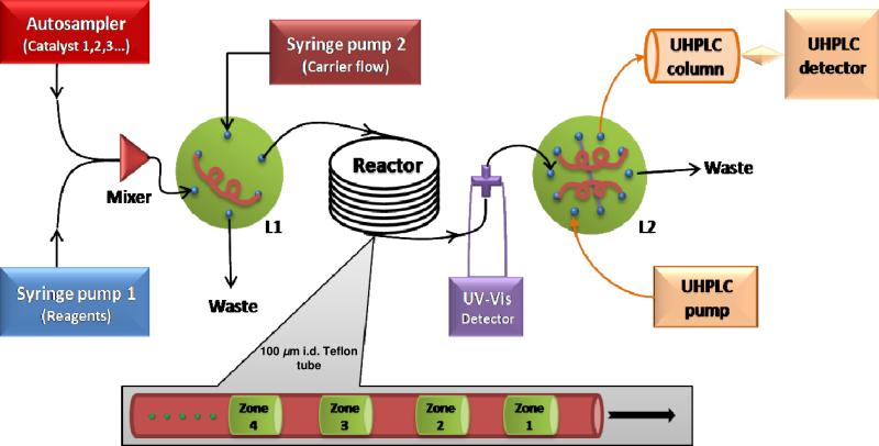
A schematic diagram of the microreactor that was used in these studies is shown in Figure 1. Catalyst solutions arriving from an autosampler are combined with the substrate solution and fed to the loop of a capillary loop injector. The contents of the loop are pumped onto the reaction capillary by a syringe pump creating a reaction zone. Reaction zones are separated naturally by the solvent in this syringe pump. The reaction time may be controlled by the length and diameter of the capillary and the flow rate of the syringe pump. The reaction time is the time required to travel the entire length of the reaction capillary. The flow can also be stopped to increase the reaction time once all of the zones are loaded into the reaction capillary, provided that all zones fit in the capillary. Thus the volume of the injected zones (including the solvent-only region) and the total volume of the reaction capillary together determine the number of zones that the reaction capillary can hold. These zones, whether they flow continuously or stop for a time prior to flowing into the detection system, are surprisingly stable toward dispersion4 because the narrow diameter of the capillary suppresses hydrodynamic dispersion of reagents by permitting radial concentration gradients to relax rapidly (Figure 2). This allows the same solvent to be used for zone separation and reaction, thus permiting multiple parallel reactions to be conducted simultaneously in a single reactor capillary where temperature can be controlled externally and reaction time can be varied by adjusting the flow rate or stopping the flow for defined time periods. The same conditions that minimize axial dispersion also permit rapid reagent mixing by simple diffusion. A Teflon/FEP capillary, rather than a more conventional SiO2 capillary, was selected for this system because of its greater stability toward acids. Also, preliminary work demonstrated that the well-known acid/base chemistry of silica led to carryover between adjacent, acid-containing, reaction zones.
Figure 1.
Block diagram of the reactor. L1 and L2 are loop injectors.
Figure 2.
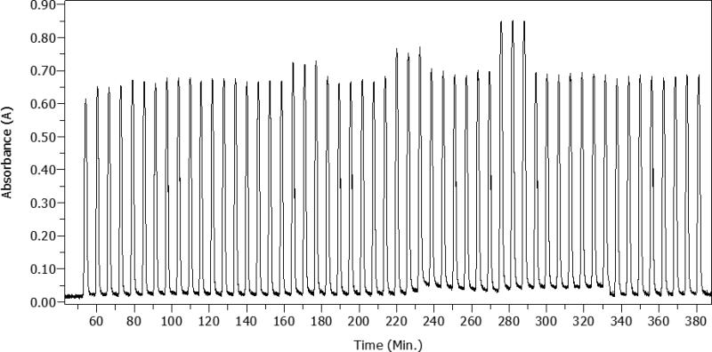
Absorbance response of 54 reaction zones passing through the UV-vis optical detector at a flow rate of 0.9 L/min for a residence time of 1 h.
An optical-fiber-based absorbance detector (220 nm) is placed at the distal end of the reaction capillary in series with the UHPLC (Figure 1). This detector measures absorbance inside the capillary rather than a separate flow cell, as typically found in HPLC detectors. Thus the zones are visualized but not destroyed. Figure 2 demonstrates the excellent zone separation. The absorbance-time trace is also used to initiate an automated sequence based on the absolute value of the absorbance resulting in injection of a portion of the zone into the UHPLC for online analysis.
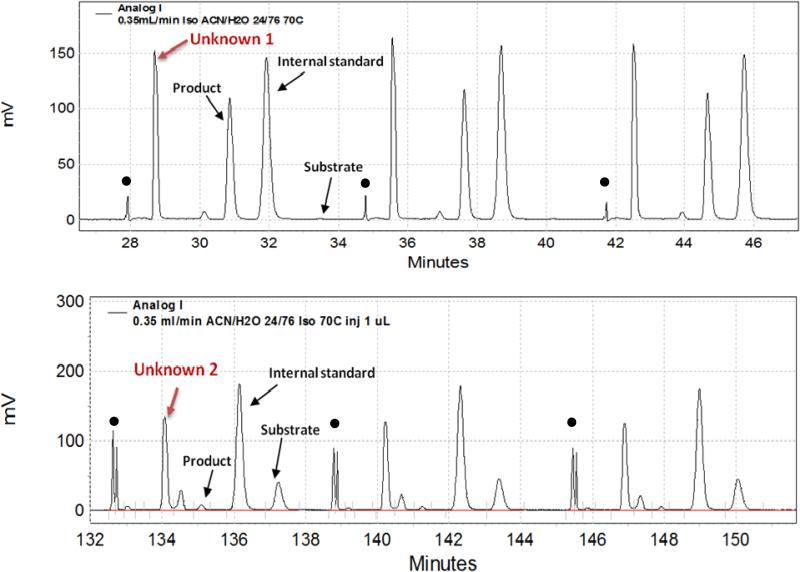
Examples of the UHPLC chromatograms from reactions catalyzed by a strong and a weak acid are shown in Figure 3. The internal standard, starting material, and products from these experiments were completely resolved by UHPLC within an approximately six minute run, consistent with the arrival frequency of the reaction zones at the injector.
Figure 3.
Top: series of three chromatograms from an HClO4-catalyzed reaction showing peaks for an unknown, product, internal standard, and substrate. The black dots indicate injection. Bottom: series of three chromatograms from a diphenylphosphoric acid-catalyzed reaction.
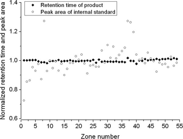
The use of an internal standard, while good practice, may not be required if the process of injection into the liquid chromatograph, which is automated, is highly reproducible. An internal standard is typically used to correct for variability in the injected sample volume. It can also be used to ascertain the reproducibility of the retention process. An internal standard adds to the complexity of the chromatogram and can be difficult to select. We reasoned that we could eliminate the internal standard if its peak area and retention time is highly reproducible in a series of injections from a variety of reaction zones. As Figure 4 shows, retention times were highly reproducible but peak areas were not.
Figure 4.
Internal standard retention time (◆) and peak area (o) relative to the mean internal standard retention time and peak area in chromatograms from all zones in a run.
We infer from the poor reproducibility of the peak area that the amount of each reaction zone that is injected is slightly variable from zone to zone. The variability arises because optical peak detection is based on absolute measured absorbance. When the absorbance in a zone exceeds a predetermined value then the zone is directed into the loop of the injector. As a result the trigger occurs after a greater fraction of the zone has passed through the detector for zones with lower absorbance relative to zones with higher absorbance. Thus an internal standard is necessary to account for this variability in the injected quantity.
Reaction Studies
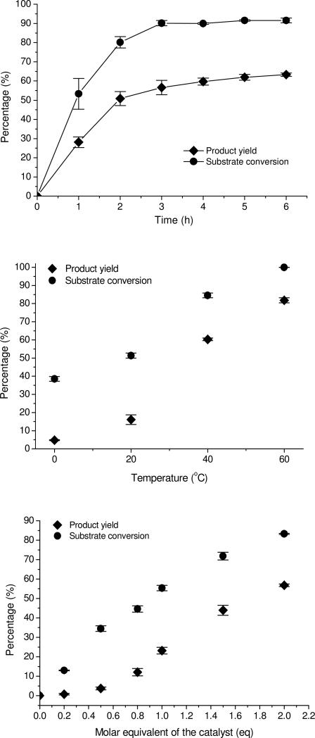
Our initial tests focused on demonstrating the ability to monitor starting material consumption and product formation as a function of time, temperature, and catalyst concentration. Success in this single reaction would portend well for the use of the reactor as a general device to identify catalysts for a range of acid-mediated processes and for applications to more ambitious objectives such as screening for asymmetric catalysis. Each reaction zone contains about 2.4 μg of substrate. In this case, the starting material is not particularly valuable, so there was no need to reduce the substrate consumption by the reactor. As the pump containing substrate (Fig. 1) ran continuously, the creation of each zone took approximately 0.3 mg of the substrate, more than 99% of which went to waste and was not recovered. Programming the syringe pump and reducing the UHPLC column size could each reduce the material requirement by a factor of 100. Thus, running numerous reactions with nanograms of starting material is feasible if the substrate is not readily accessible. We used diphenylphosphoric acid as the catalyst in these studies. The data for these experiments are shown in Figure 5. Each reaction was run in triplicate. The excellent reproducibility between runs is demonstrated by the small error bars in Fig. 5. The small standard errors reflect both reproducible reaction conditions and reproducible analysis of the reaction zones. We note in particular that the reproducibility of the data is better than the reproducibility of the internal standard peak areas shown above, thereby validating the benefits of internal standard incorporation for reducing errors arising from injection volume variability. These curves demonstrate that reactions show expected behavior in the microreactor, with starting material consumption and product formation increasing as time, temperature, and catalyst concentration increase. Thus important information broadly defining the range of behavior of weak Brønsted acid catalysts can be obtained in a short time with minimal material investment, indicating that the microreactor is well-suited for rapid mechanistic studies of acid-mediated processes.
Figure 5.
Variations of yield and substrate conversion as a function of reaction time, temperature, and catalyst concentration. Plotted data are mean ± SEM (standard error) (n=3). Top: 0.01 M substrate and 0.01 M 4-ethylanisole (internal standard) in CH3CN with 1 molar equivalent of diphenyl phosphoric acid at 40 °C for various times. Middle: 0.01 M substrate and 0.01 M 4-ethylanisole with 1 molar equivalent of diphenyl phosphoric acid at various temperatures for 1 h. Bottom: 0.01 M substrate and 0.01 M 4-ethylanisole with varying diphenylphosphoric acid concentrations at 40 °C for 1 h.
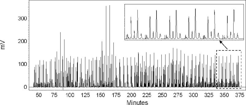
Our next objective was to use the microreactor to identify new catalysts to promote the reaction. We chose to use reaction times of 1 h at a reaction temperature of 0 °C and of 0.5 h at a reaction temperature of 40 °C for catalyst screening. We chose a catalyst loading of 0.2 eq. to identify species that turn over. Thus, we loaded the autosampler with solutions of several Brønsted and Lewis acids. The automated microreactor combined them with a solution of substrate, and injected them into the reaction capillary. Each of the acid catalysts was tested in triplicate. All reactions could be conducted within 6 h and required only 17.4 mg (syringe pump 1 (Figure 1) flowing at 15 μL/min for 6 h with 0.01 M substrate) or less than 400 μg per reaction of the cyclization substrate. The zones were monitored by UHPLC to determine the extent of substrate consumption and product formation (Figure 6). Ratios of product formation to starting material consumption were calculated to determine the specificity of each catalyst under the prevailing conditions. The results are shown in Table 1. We drew several conclusions from the data. Reactions were more efficient at 40 °C than at 0 °C. Weak Brønsted acids such as Cl3CCO2H and F3CCO2H do not promote substantial product formation or starting material consumption. Strong Brønsted acids such as HCl, HNO3, H2SO4, and HClO4 were more effective with respect to starting material consumption. The rate of substrate consumption for reactions that were catalyzed by Brønsted acids roughly correlated with aqueous pKa trends, though exact pKa values for many Brønsted acids in CH3CN can be elusive.11 However, except for perchloric acid, selectivity for cyclization product formation is mediocre. The Lewis acids generally performed better than the Brønsted acids. The lanthanide triflates are by far the most promising catalysts, showing complete starting material consumption and high selectivity for the desired cyclization product. Er(OTf)3, an oxophilic catalyst that is attracting increased attention for acid-mediated processes,12 showed the most promising profile.
Figure 6.
Series of chromatograms from the 54 reaction zones. The inset chromatogram shows the peaks in the last six reaction zones representing two catalyts.
Table 1.
Starting material consumption and product formation from various catalysts.
| Entry | Catalyst | Temperature, 0 °C |
Temperature, 40 °C |
||||
|---|---|---|---|---|---|---|---|
| Yield (%)a | Conversiona (%) | Ratio of yield/conversion (%)b | Yield (%) | Conversion (%) | Ratio of yield/conversion (%) | ||
| 1 | H2SO4 (98%) | 9.4 ± 1.2 | 79.5 ± 0.6 | 11.8 | 61.4 ± 0.3 | 98.8 ± 0.1 | 62.1 |
| 2 | H3PO4 (85%) | 2.2 ± 2.4 | 53.6 ± 4.0 | 4.1 | 40.9 ± 0.2 | 72.1 ± 0.1 | 56.7 |
| 3 | HNO3 (70%) | 0 | 44.8 ± 2.1 | 0 | 38.7 ± 1.2 | 71.5 ± 0.5 | 54.1 |
| 4 | HClO4 (70%) | 63.3 ± 0.8 | 98.3 ± 0.2 | 64.3 | 80.1 ± 3.0 | 99.6 ± 0.6 | 80.4 |
| 5 | HCl (38%) | 2.6 ± 2.4 | 55.4 ± 4.1 | 4.8 | 47.1 ± 3.9 | 84.8 ± 3.1 | 55.6 |
| 6 | CH3SO3H | 4.4 ± 0.8 | 69.9 ± 3.3 | 6.3 | 61.4 ± 0.3 | 97.9 ± 0.1 | 62.6 |
| 7 | p-TsOH•H2O | 11.8 ± 0.3 | 78.8 ± 1.1 | 14.9 | 61.5 ± 0.1 | 100 | 61.5 |
| 8 | CF3COOH | 0 | 22.8 ± 6.0 | 0 | 5.1 ± 2.4 | 24.7 ± 5.4 | 20.7 |
| 9 | Cl3CCOOH | 0 | 17.3 ± 0.5 | 0 | 1.3 ± 0.3 | 8.2 ± 2.9 | 16.3 |
| 10 | SnCl4 | 48.6 ± 1.5 | 96.9 ± 0.2 | 50.1 | 78.5 ± 0.3 | 100 | 78.5 |
| 11 | SbCl5 | 51.1 ± 0.3 | 98.8 ± 0.2 | 51.6 | 58.8 ± 0.6 | 100 | 58.8 |
| 12 | BF3•OEt2 | 52.3 ± 0.4 | 99.0 ± 0.1 | 52.8 | 70.0 ± 0.2 | 100 | 70.0 |
| 13 | BF3•THF | 56.7 ± 0.2 | 99.0 ± 0.1 | 57.2 | 65.9 ± 0.3 | 100 | 65.9 |
| 14 | Eu(OTf)3 | 32.8 ± 6.4 | 91.1 ± 4.5 | 36.1 | 88.2 ± 5.4 | 97.2 ± 0.9 | 88.2 |
| 15 | Tb(OTf)3 | 25.8 ± 2.8 | 83.9 ± 1.3 | 30.8 | 85.5 ± 3.1 | 91.8 ± 1.2 | 93.2 |
| 16 | Er(OTf)3 | 23.6 ± 1.4 | 82.3 ± 0.8 | 28.7 | 93.2 ± 0.3 | 95.7 ± 0.1 | 97.4 |
| 17 | Ho(OTf)3 | 21.0 ± 0.9 | 80.6 ± 0.2 | 26.1 | |||
| 18 | Yb(OTf)3 | 20.0 ± 1.0 | 78.1 ± 0.7 | 25.6 | |||
Yields of product and conversions of substrate are determined by UHPLC. Yield ± conversion = mean ± SE (standard error) (n=3)
Percentage ratio of yield to conversion.
By-product analysis
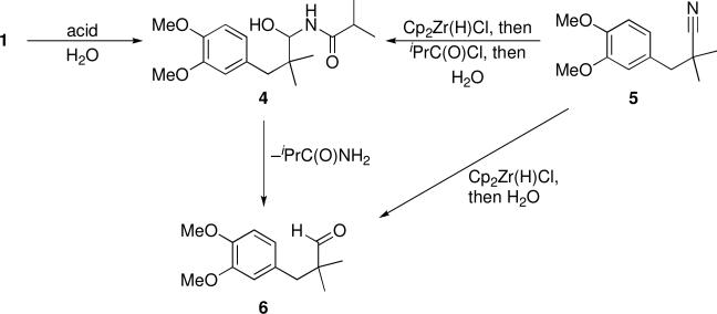
An advantage of the microreactor approach with chromatographic detection is that product formation patterns can be detected. Identifying byproducts that appear consistently is important to provide information regarding the reaction pathway and/or product stability. In our studies UHPLC analysis showed that three major byproducts were formed in reactions that did not produce the desired bicyclic amide efficiently. In fact, the byproduct distribution was distinctly different in reactions catalyzed by the weaker acids in comparison to the stronger acids. We switched from online UHPLC analysis to offline GCMS (electron impact ionization) and LCMS (electrospray ionization) detection of byproducts in reactions in vials in an effort to identify the structures of these products (see Supplementary Information). A major byproduct that was formed (Scheme 2) when weak acids were used showed an [M + Na]+ ion at m/z = 332.2. This mass is consistent with ionization followed by addition of H2O to the acyliminium ion to form acyl hemiaminal 4. The identity of 4 was confirmed by preparing it independently from nitrile 5 through a sequence of hydrozirconation, acylation, and water addition,5a subjecting it to UHPLC analysis, and observing an identical retention time to the unknown by-product. The identification of 4 led us to postulate that the other major by-product from these reactions was aldehyde 6, which arises from the breakdown of 4. This structural assignment was also confirmed by independent synthesis and UHPLC analysis. While water was not deliberately added to these reactions, it was not rigorously excluded and it was used in the solvent for UHPLC detection, leading to two potential sources for by-product formation.
Scheme 2.
Side reactions with weak acids, and independent by-product synthesis.
Strong acids produced an additional by-product with an [M + Na]+ m/z value of 286.0, corresponding to a formal loss of C2H4 from the cyclization product. This molecular formula suggested that the product arose (Scheme 3) from the acid-mediated ionization of 3 to form benzylic cation 7 followed by a Ritter reaction12 that proceeds through the sequential addition of acetonitrile (solvent) and water to yield 8. The identity of 8 was again confirmed by independent synthesis through subjecting 5 to hydrozirconation, acylation with AcCl, and Friedel-Crafts cyclization mediated by ZnCl28 and observing identical UHPLC behavior to the by-product.
Scheme 3.
Side reaction with strong acids and independent by-product synthesis.
Identifying the side products of the reaction provides valuable information regarding the behavior of substrates and products under reaction conditions. The present study shows that acids must be potent but not too potent for the reaction to proceed efficiently. Mechanistic hypotheses regarding the formation of the side products will provide guidance for selecting acids for other substrates as the scope of the process is expanded.
Application to a preparative scale reaction
The results from the catalyst screening protocol should be applicable to preparative scale reactions. When we applied the conditions that were studied in the microreactor (0.01 M substrate in CH3CN, 0.2 eq Er(OTf)3, 40 °C, 30 min), however, minimal product formation was observed. Extending the reaction time to 8 h and increasing the catalyst loading to 1 eq resulted in the formation of 3 in 91% isolated yield when 150 mg of substrate was employed. Significantly enhanced reaction selectivity and rate are often found in liquid-phase reactions in microreactors compared to batch reactions. We postulate that the rate difference between the reaction in the microreactor and the preparative scale reaction arise from the highly efficient mixing in the microreactor. Increasing the mixing rate could increase the conversion rate of the tight ion pair that forms initially and reversibly upon acylaminal dissociation to a solvent separated ion pair that would engage in the cyclization reaction more readily. Despite the rate differences, this study demonstrated that unique catalysts for efficient preparative scale reactions can be identified by screening with this microreactor.
Conclusions
We have reported a new flow-through capillary-based microreactor coupled with UHPLC detection that allows for near-real-time evaluation of reaction efficiency under a variety of conditions or in the presence of different catalysts. The microreactor is based upon the establishment of reaction zones that are stable toward dispersion because of the narrow diameter of the capillary, the low flow velocity through the capillary, and the relatively high diffusion coefficients of the catalysts and substrate. Reaction results are highly reproducible and display expected behavior upon increasing reaction time, temperature, and catalyst concentration. The microreactor that was described in this manuscript has numerous applications beyond those described above. The reproducibility and high throughput capacity will allow for mechanistic studies of acid-catalyzed reactions by facilitating labor intensive determinations of linear free energy relationships. Employing a separation system with the capacity to discriminate between enantiomers will be extremely useful for identifying asymmetric catalysts for enantioselective reactions. These objectives are currently being pursued in our laboratories and the results will be reported in due course.
Experimental Section
Microreactor setup
Catalysts sampled by the autosampler (25 μL sampling volume) are combined with reagents pushed by syringe pump 1 at equal flow rates (15 μL/min) through a home-made nanoliter-volume tee mixer (Figure 1). The combined fluids pass through and fill a loop (750 nL) in a 6-port 2-position HPLC injector (L1). We program the autosampler to control the loading time for the catalyst and reagents (which are determined by sampling volume and loading flow rate). For instance, 25 μL catalyst solution is sampled by the autosampler and the loading flow rate is 15 μL/min, then the loading time is about 25/15=1.6 min. When the loading time is reached, the autosampler triggers L1 to switch to the ‘inject position’ and contents of the loop are then injected into the reaction capillary by syringe pump 2 at a constant flow rate. This injection time is also controlled by the autosampler. This time is determined by the loop volume and flow rate of syringe pump 2. When the injection is over, the autosampler will trigger L1 to switch back to ‘load position’ and then the next catalyst/reagent zone will be loaded and injected following the same procedures. We also added a ‘stop time’ step to the program in the autosampler. During this time the autosampler is rinsed in order to prevent carryover in the autosampler. The periodic loading of catalysts by the autosampler with the constant flow of syringe pump 1 generates a series of reaction zones in the reaction capillary which contain different catalysts with common reagents. These zones are separated by the carrier solvent CH3CN deliver by syringe pump 2. The online UHPLC analysis time must be less than the total of the times for ‘loading’, ‘injection’ and ‘stop time’ to ensure continuous analysis of individual serial zones.
The microreactor capillary is a piece of 100 μm i.d., 1/16” o.d., 6.1 m long Teflon capillary tube. A water/oil bath is used for heating or cooling the reaction capillary to the required temperature. Syringe pump 2 is constantly delivering carrier solvent CH3CN to push all reaction zones through the reactor. The reaction time is controlled by flow rate of CH3CN and the length of reaction capillary. When the reaction zones come out of the reactor, they first go through a flow cell monitored by a UV-Vis fiber optic absorbance detector before entering the 10-port 2-position double-loop (1.0 μL) valve (L2). L2 is a 15000-psi-high-pressure valve. It enables the loading of one loop from the reaction capillary while the contents of the other loop are analyzed by UHPLC. The UHPLC runs continuously. L2 is triggered by signals coming from the fiber optic absorbance detector. Thus a single chromatographic run contains the chromatograms of all of the reaction zones in sequence.
UHPLC analysis
The isocratic separation was carried out with a mobile phase of CH3CN:H2O (24:76 v/v) at a flow rate of 0.35 mL/min and a temperature of 70 °C. The injection volume is 1.0 μL which is the size of the loop of the 10-port injector. A single chromatographic run is set to analyze all reaction zones.
Reactions in the microreactor
The cyclization reaction was carried out in a continuous flow stream of CH3CN in the microreactor at a constant temperature. Solutions of Brønsted and Lewis acids (20 mol% in CH3CN) were placed in 1.5-mL glass autosampler vials. The catalyst vials were placed in the tray of the autosampler. The reagents (0.01 M substrate and 0.01 M 4-ethylanisole (internal standard) in CH3CN) were loaded in a 2.5 mL gas-tight syringe and constantly driven by syringe pump 1. Syringe pump 2 delivered the carrier solvent (CH3CN) at a constant flow rate to push all reaction zones through the reactor followed by online UHPLC analysis.
General synthesis experimental
1H NMR and 13C NMR spectra were recorded at 300 MHz and 75 MHz, respectively. The chemical shifts are given in parts per million (ppm) on the delta (δ) scale. The solvent peak was used as a reference value, for 1H NMR: CDCl3 = 7.27 ppm, for 13C NMR: CDCl3 = 77.23. Data are reported as follows: s = singlet; d = doublet; t = triplet; q = quartet; dd = doublet of doublets; dt = doublet of triplets; br = broad. Samples for IR were prepared as a thin film on a NaCl plate by dissolving the compound in CH2Cl2 and then evaporating the CH2Cl2. Methylene chloride was distilled under N2 from CaH2. 1,2–Dichloroethane was dried over 4 Å molecular sieves. Analytical TLC was performed on pre-coated (25 mm) silica gel 60F-254 plates. Visualization was done under UV (254 nm). Flash chromatography was done using 60 Å silica gel. Reagent grade ethyl acetate, diethyl ether, pentane and hexanes (commercial mixture) were used as is for chromatography. All reactions were performed in oven or flame-dried glassware under a positive pressure of N2 with magnetic stirring unless otherwise noted. The synthesis and purification of reaction substrate 1 was conducted according to a literature protocol.8
N-(3-(3,4-dimethoxyphenyl)-1-hydroxy-2,2-dimethylpropyl) isobutyramide (4)
To a solution of nitrile 5 (219 mg, 1.0 mmol) in dichloromethane (10 mL) was added Cp2Zr(H)Cl (319 mg, 1.24 mmol). The reaction mixture was stirred for 30 min at room temperature. Isobutyryl chloride (132 μL, 1.24 mmol) was added and mixture was stirred for another 15 min. Water (15 mL) was added and the mixture was stirred for 30 min at room temperature. The reaction was extracted with ethyl acetate and the extracts were washed with brine. The organic layer was dried over Na2SO4. The solvent was removed and the residue was purified by column chromatography (hexanes: ethyl acetate : triethyl amine = 1:1:0.02) to give 4 (230 mg, 74%). 1H NMR (300 MHz, CDCl3) δ 6.81-6.70 (m, 3H), 5.97 (d, 1H, J = 8.4 Hz), 5.09 (d, 1H, J = 8.4 Hz), 3.86 (s, 6H), 2.68 (d, 1H, J = 13.2 Hz), 2.57 (d, 1H, J = 13.2 Hz), 2.26 (sept, 1H, J = 6.9 Hz), 1.07 (d, 3H, J = 6.9 Hz), 1.06 (d, 3H, J = 6.9 Hz), 0.96 (s, 6H); 13C NMR (75 MHz, CDCl3) δ 177.7, 148.2, 147.4, 130.4, 122.6, 113.9, 110.6, 78.8, 55.7, 55.6, 43.3, 38.2, 35.5, 23.8, 22.0, 19.2, 18.9; IR (neat) 3362, 2966, 2934, 2873, 1657, 1515, 1465, 1262, 1236, 1156, 1029, 764 cm-1; HRMS (EI) m/z calcd for C17H27NO4 (M+) 309.1940, found 309.1941.
3-(3,4-dimethoxyphenyl)-2,2-dimethylpropanal (6)
To a solution of nitrile 5 (110 mg, 0.5 mmol) in dichloromethane (5 mL) was added Cp2Zr(H)Cl (156 mg, 0.60 mmol).The reaction mixture was stirred for 30 min at room temperature. H2O (500 μL, 27.7 mmol) was added dropwise and the mixture was stirred for another 30 min at room temperature. The reaction was quenched with NaHCO3 (sat. aqueous). The mixture was extracted with ethyl acetate and the extracts were washed with H2O and brine. The organic layer was dried over Na2SO4. The solvent was removed and the residue was purified by column chromatography (hexanes: ethyl acetate = 8:2) to give 6 (99 mg, 89%). 1H NMR (300 MHz, CDCl3) δ 9.60 (s, 1H), 6.80-6.76 (d, 1H, J = 8.1 Hz), 6.68-6.61 (m, 2H), 3.869 (s, 3H), 3.867 (s, 3H), 2.75 (s, 2H), 1.07 (s, 6H); 13C NMR (75 MHz, CDCl3) δ 206.2, 148.4, 147.7, 129.4, 122.3, 113.4, 110.9, 55.8, 7.0, 42.9, 21.5; IR (neat) 2963, 2934, 2835, 1721, 1589, 1515, 1262, 1190, 1156, 1029 cm-1; HRMS (EI) m/z calcd for C13H18O3Na (MNa+) 245.1154, found 245.1157.
N-(5,6-dimethoxy-2,2-dimethyl-2,3-dihydro-1H-inden-1-yl)acetamide (8)
To a solution of 3-(3,4-dimethoxyphenyl)-2,2-dimethylpropanenitrile7 (219 mg, 1.0 mmol) in dichloromethane (10 mL) was added Cp2Zr(H)Cl (319 mg, 1.24 mmol). The reaction mixture was stirred for 30 min at room temperature. Acetyl chloride (88 μL, 1.2 mmol) was added and mixture was stirred for another 15 min. ZnCl2 (400 μL, 1.0 M solution in diethyl ether, 0.4 mmol) was added and the mixture was stirred for 2 h at room temperature. The reaction was quenched with NaHCO3 (sat. aqueous). The mixture was extracted with ethyl acetate and the extracts were washed with H2O and brine. The organic layer was dried over Na2SO4. The solvent was removed and the residue was purified by column chromatography (hexanes: ethyl acetate = 1:1) to give 8 (250 mg, 95%). 1H NMR (300 MHz, CDCl3) δ 6.73 (s, 1H), 6.72 (s, 1H), 5.47 (d, 1H, J = 10.2 Hz), 5.17(d, 1H, J = 9.6 Hz), 3.87 (s, 3H), 3.86 (s, 3H), 2.69 (s, 2H), 2.10 (s, 3H), 1.24 (s, 3H), 1.01 (s, 3H); 13C NMR (75 MHz, CDCl3) δ 169.8, 148.9, 148.1, 133.9, 133.8, 107.8, 107.2, 62.4, 55.9, 55.8, 45.5, 44.3, 27.5,23.3, 22.7; IR (neat) 3260, 2958, 2926, 1641, 1549, 1503, 1464, 1369, 1315, 1289, 1114, 750 cm-1; HRMS (EI) m/z calcd for C15H21NO3 (M+) 263.1521, found 263.1527.
N-(5,6-dimethoxy-2,2-dimethyl-2,3-dihydro-1H-inden-1-yl)isobutyramide (3) (preparative scale)
A flame-dried 100 mL round bottom flask charged with 1 (150 mg, 0.46 mmol) and a stirring bar was pumped and purged with argon for three times before acetonitrile (46 mL) was added via syringe. Er(OTf)3 (285 mg, 0.46 mmol) was added as powder in one portion and the flask was capped with a glass stopper. The resulting clear solution was stirred at 40 °C for 20 h. The reaction was quenched with NaHCO3 (sat. aqueous). The mixture was extracted with ethyl acetate and the extracts were washed with brine. The organic layer was dried over Na2SO4. The solvent was removed and the residue was purified by column chromatography (hexanes: ethyl acetate = 7:3) to give 3 (124 mg, 92%). All spectral data are consistent with previously reported values.8 1H NMR (300 MHz, CDCl3) δ 6.72 (s, 1H), 6.70 (s, 1H), 5.46 (d, 1H, J = 9.9 Hz), 5.17(d, 1H, J = 9.6 Hz), 3.87 (s, 3H), 3.85 (s, 3H), 2.70 (s, 2H), 2.44 (sept, 1H, J = 6.9 Hz), 1.24 (s, 3H), 1.23 (d, 6H, J = 6.6 Hz), 1.00 (s, 3H); 13C NMR (125 MHz, CDCl3) δ 177.1, 149.3, 148.5, 134.4, 134.3, 108.2, 107.6, 62.3, 56.24, 56.18, 46.0, 44.7, 36.1, 29.9, 28.0, 23.1, 20.2, 19.9.
Supplementary Material
Acknowledgement
This work was generously supported by the NIH through grant P50-GM06082 and the NSF (PEF) through grant CHE-0848299.
Footnotes
Supporting Information Available: Synthetic protocols, side reaction analysis by GC-MS and LCMS, 1H and 13C NMR spectra of new compounds, sampling program for catalyst loading, microreactor parts and specifications. This material is available free of charge via the Internet at http://pubs.acs.org.
References
- 1.a Ahmed-Omer B, Brandt JC, Wirth T. Org. Biomol. Chem. 2007;5:733–740. doi: 10.1039/b615072a. [DOI] [PubMed] [Google Scholar]; b Fletcher PDI, Haswell SJ, Pombo-Villar E, Warrington BH, Watts P, Wong SYF, Zhang X. Tetrahedron. 2002;58:4735–4757. [Google Scholar]; c Haswell SJ, Middleton RJ, O'Sullivan B, Skelton V, Watts P, Styring P. Chem. Commun. 2001:391–398. [Google Scholar]; d Jähnisch K, Hessel V, Löwe H, Baerns M. Angew. Chem., Int. Ed. 2004;43:406–446. doi: 10.1002/anie.200300577. [DOI] [PubMed] [Google Scholar]; e Anspach JA, Maloney TD, Colon LA. J. Sep. Sci. 2007;30:1207–1213. doi: 10.1002/jssc.200600535. [DOI] [PubMed] [Google Scholar]; f Mason BP, Price KE, Steinbacher JL, Bogdan AR, McQuade DT. Chem. Rev. 2007;107:2300–2318. doi: 10.1021/cr050944c. [DOI] [PubMed] [Google Scholar]; g Roberge DM, Bieler N, Thalmann M. PharmaChem. 2006;5:14–17. [Google Scholar]; h Schwalbe T, Autze V, Wille G. Chimia. 2002;56:636–646. [Google Scholar]; i Seeberger PH, Geyer K, Codee JDC. Ernst Schering Found. Symp. Proc. 2007:1–19. doi: 10.1007/2789_2007_025. [DOI] [PubMed] [Google Scholar]; j Watts P. Curr. Opin. Drug Discovery Dev. 2004;7:807–812. [PubMed] [Google Scholar]; k Watts P, Haswell SJ. Chem. Eng. Technol. 2005;28:290–301. [Google Scholar]; l Watts P, Wiles C. Org. Biomol. Chem. 2007;5:727–732. doi: 10.1039/b617327f. [DOI] [PubMed] [Google Scholar]; m Kobayashi J, Mori Y, Kobayashi S. Chem. Asian J. 2006;1:22–35. doi: 10.1002/asia.200600058. [DOI] [PubMed] [Google Scholar]; n Fukuyama T, Rahman RT, Sato M, Ryu I. Synlett. 2008:151–163. [Google Scholar]; o Yoshida J.-i., Nagaki A, Yamada T. Chem. Eur. J. 2008;14:7450–7459. doi: 10.1002/chem.200800582. [DOI] [PubMed] [Google Scholar]
- 2.For reviews, see: Gennari C, Piarulli U. Chem. Rev. 2003;103:3071–3100. doi: 10.1021/cr020058r. Dahmen S, Brase S. Synthesis. 2001:1431–1449. Reetz MT. Angew. Chem., Int. Ed. 2001;40:284–310. Shimizu KD, Snapper ML, Hoveyda AH. Chem. Eur. J. 1998;4:1885–1889.
- 3.a De Bellefon C, Tanchoux N, Caravieilhes S, Grenoullet P, Hessel V. Angew. Chem., Int. Ed. 2000;39:3442–3445. doi: 10.1002/1521-3773(20001002)39:19<3442::aid-anie3442>3.0.co;2-q. [DOI] [PubMed] [Google Scholar]; b Garcia-Egido E, Spikmans V, Wong SYF, Warrington BH. Lab Chip. 2003;3:73–76. doi: 10.1039/b302381h. [DOI] [PubMed] [Google Scholar]; c Greenway GM, Haswell SJ, Morgan DO, Skelton V, Styring P. Sens. Actuators, B. 2000;B63:153–158. [Google Scholar]; d Pennemann H, Hessel V, Kost HJ, Loewe H, de Bellefon C, Pestre N, Lamouille T, Grenouillet P. Better Processes for Bigger Profits, International Conference on Process Intensification for the Chemical Industry, 5th, Maastricht, Netherlands, Oct. 13-15, 2003.2003. pp. 137–147. [Google Scholar]; e Zech T, Klein J, Schunk SA, Johann T, Schueth F, Kleditzsch S, Deutschmann O. High-Throughput Analysis. 2003:491–523. [Google Scholar]; f Suga S, Okajima M, Fujiwara K, Yoshida J.-i. J. Am. Chem. Soc. 2001;123:7941–7942. doi: 10.1021/ja015823i. [DOI] [PubMed] [Google Scholar]
- 4.Shi G, Hong F, Liang Q, Fang H, Nelson S, Weber SG. Anal. Chem. 2006;78:1972–1979. doi: 10.1021/ac051844+. [DOI] [PubMed] [Google Scholar]
- 5.Ratner DM, Murphy ER, Jhunjhunwala M, Snyder DA, Jensen KF, Seeberger PH. Chem. Commun. 2005:578–580. doi: 10.1039/b414503h. [DOI] [PubMed] [Google Scholar]
- 6.For examples of other microreactor/detector systems, please see: Hatakeyama T, Chen DL, Ismagilov R. J. Am. Chem. Soc. 2006;128:2518–2519. doi: 10.1021/ja057720w. Wang J, Sui G, Mocharla VP, Lin RJ, Phelps ME, Kolb HC, Tseng H-R. Angew. Chem. Int. Ed. 2006;45:5276–5281. doi: 10.1002/anie.200601677. Murphy ER, Martinelli JR, Zaborenko N, Buchwald SL, Jensen KF. Angew. Chem. Int. Ed. 2007;46:1734–1737. doi: 10.1002/anie.200604175. Knudsen KR, Holden J, Ley SV, Ladlow M. Adv. Synth. Catal. 2007;349:535–538. Goodell JR, McMullen JP, Zaborenko N, Maloney JR, Ho C-X, Jensen KF, Porco JA, Jr., Beeler AB. J. Org. Chem. 2009;74:6169–6180. doi: 10.1021/jo901073v.
- 7.a Wan S, Green ME, Park J-H, Floreancig PE. Org. Lett. 2007;9:5385–5388. doi: 10.1021/ol702184n. [DOI] [PMC free article] [PubMed] [Google Scholar]; b DeBenedetto MV, Green ME, Wan S, Park J-H, Floreancig PE. Org. Lett. 2009;11:835–838. doi: 10.1021/ol802764j. [DOI] [PMC free article] [PubMed] [Google Scholar]
- 8.Xiao Q, Floreancig PE. Org. Lett. 2008;10:1139–1142. doi: 10.1021/ol8000409. [DOI] [PubMed] [Google Scholar]
- 9.a Petrini M, Torregiani E. Synthesis. 2007:159–186. [Google Scholar]; b Maryanoff BE, Zhang H-C, Cohen JH, Turchi IJ, Maryanoff CA. Chem. Rev. 2004;104:1431–1628. doi: 10.1021/cr0306182. [DOI] [PubMed] [Google Scholar]; c Speckamp WN, Moolenaar MJ. Tetrahedron. 2000;56:3817–3856. [Google Scholar]
- 10.For representative examples, see: Uraguchi D, Terada M. J. Am. Chem. Soc. 2004;126:5356–5357. doi: 10.1021/ja0491533. Uraguchi D, Sorimachi K, erada M. J. Am. Chem. Soc. 2004;126:11804–11805. doi: 10.1021/ja046185h. Uraguchi D, Sorimachi K, Terada M. J. Am. Chem. Soc. 2005;127:9630–9631. doi: 10.1021/ja051922a. Rowland GB, Zhang H, Rowland EB, Chennamadhavuni S, Wang Y, Antilla JC. J. Am. Chem. Soc. 2005;127:15696–15697. doi: 10.1021/ja0533085. Terada M, Sorimachi K. J. Am. Chem. Soc. 2007;129:292–293. doi: 10.1021/ja0678166. Rowland GB, Rowland EB, Liang Y, Perman JA, Antilla JC. Org. Lett. 2007;9:2609–2611. doi: 10.1021/ol0703579. Li G, Rowland GB, Rowland EB, Antilla JC. Org. Lett. 2007;9:4065–4068. doi: 10.1021/ol701881j. Terada M, Machioka K, Sorimachi K. J. Am. Chem. Soc. 2007;129:10336–10337. doi: 10.1021/ja0739584. Raheem IT, Thiara PS, Peterson EA, Jacobsen EN. J. Am. Chem. Soc. 2007;129:13404–13405. doi: 10.1021/ja076179w. Raheem IT, Thiara PS, Jacobsen EN. Org. Lett. 2008;10:1577–1580. doi: 10.1021/ol800256j. Li G, Fronczek FR, Antilla JC. J. Am. Chem. Soc. 2008;130:12216–12217. doi: 10.1021/ja8033334. Li G, Antilla JC. Org. Lett. 2009;11:1075–1078. doi: 10.1021/ol802860u. Terada M, Machioka K, Sorimachi K. Angew. Chem., Int. Ed. 2009;48:2553–2556. doi: 10.1002/anie.200805385. Terada M, Toda Y. J. Am. Chem. Soc. 2009;131:6354–6355. doi: 10.1021/ja902202g. Muratore ME, Holloway CA, Pilling AW, Storer RI, Trevitt G, Dixon DJ. J. Am. Chem. Soc. 2009;131:10796–10797. doi: 10.1021/ja9024885. Peterson EA, Jacobsen EN. Angew. Chem., Int. Ed. 2009;48:6328–6331. doi: 10.1002/anie.200902420.
- 11.For spectrophotometric determination of pKa values for several Brønsted acids in acetonitrile, see: Kütt A, Leito I, Karljurand I, Sooväli L, Vlasov VM, Yagupolskii LM, Koppel IA. J. Org. Chem. 2006;71:2829–2838. doi: 10.1021/jo060031y.
- 12.a Dalpozzo R, De Nino A, Maiuolo L, Nardi M, Procopio A, Tagarelli A. Synthesis. 2004:496–498. [Google Scholar]; b Procopio A, Dalpozzo R, De Nino A, Maiuolo L, Russo B, Sindona G. Adv. Synth. Catal. 2004;346:1465–1470. [Google Scholar]; c Procopio A, Dalpozzo R, De Nino A, Nardi M, Sindona G, Tagarelli A. Synlett. 2004:2633–2635. [Google Scholar]; d Procopio A, Dalpozzo R, De Nino A, Maiuolo L, Nardi M, Russo B. Adv. Synth. Catal. 2005;347:1447–1450. [Google Scholar]; e Procopio A, Gaspari M, Nardi M, Oliverio M, Rosati O. Tetrahedron Lett. 2008;49:2289, 2293. [Google Scholar]
- 13.Ritter JJ, Minieri PP. J. Am. Chem. Soc. 1948;70:4045–4048. doi: 10.1021/ja01192a022. [DOI] [PubMed] [Google Scholar]
Associated Data
This section collects any data citations, data availability statements, or supplementary materials included in this article.


