Abstract
Purpose: Measuring tissue temperature distribution during electromagnetically induced hyperthermia (HT) is challenging. High resistance thermistors with nonmetallic leads have been used successfully in commercial HT systems for about three decades. The single 1 mm thick temperature sensing element is mechanically moved to measure tissue temperature distributions. By employing a single thermometry probe containing a fixed linear sensor array temperature, distributions during therapy can be measured with greater ease. While the first attempts to use fiber Bragg grating (FBG) technology to obtain multiple temperature points along a single fiber have been reported, improvement in the detection system’s stability were needed for clinical applications. The FBG temperature sensing system described here has a very high temporal stability detection system and an order of magnitude faster readout than commercial systems. It is shown to be suitable for multiple point fiber thermometry during microwave hyperthermia when compared to conventional mechanically scanning probe HT thermometry.
Methods: A polymer coated fiber Bragg grating (PFBG) technology is described that provides a number of FBG thermometry locations along the length of a single optical fiber. The PFBG probe developed is tested under simulated microwave hyperthermia treatment to a tissue equivalent phantom. Two temperature probes, the multiple PFBG sensor and the Bowman probe, placed symmetrically with respect to a microwave antenna in a tissue phantom are subjected to microwave hyperthermia. Measurements are made at start of HT and 85 min later, when a 6 °C increase in temperature is registered by both probes, as is typical in clinical HT therapy. The optical fiber multipoint thermometry probe performs highly stable, real-time thermometry updating each multipoint thermometry scan over a 5 cm length every 2 s. Bowman probe measurements are acquired simultaneously for comparison. In addition, the PFBG sensor’s detection system drift over 10 h is measured separately to evaluate system stability for clinical applications.
Results: The temperature profiles measured by the two probes simultaneously under microwave HT are in good agreement showing mean differences of 0.25 °C. The stability of the detection system is better than 0.3 °C with response times of the PFBG sensor system of 2 s for each scan over ten points.
Conclusions: The single fixed multipoint fiber thermometry capability compares favorably with the scanning Bowman probe data. This offers an enabling alternative to either scanning or bundled single point temperature probes for distributed thermometry in clinical applications.
Keywords: fiber Bragg grating, fast readout, FBG, polymer coating, temperature gradient, PFBG, hyperthermia, temperature profile, thermometry, multisensor probe
INTRODUCTION
Microwave hyperthermia (HT) is an effective treatment for the symptoms of benign prostatic hyperplasia1, 2 and an effective adjuvant for radiation therapy of cancer.3 Hyperthermic dose is generally expressed as a function of the tissue temperature achieved and the exposure duration. The most common method of determining tissue temperature during clinical HT treatment is by using thermometry probes afterloaded into plastic catheters implanted throughout the treatment region.4
During HT treatments, as few of these implanted catheters as possible are used in order to minimize the potential for morbidity associated with temperature measurement;5 hence, maximizing the number of temperature measurement loci along each catheter is advantageous. This was initially accomplished by manually or robotically sliding a single sensor probe along the catheter.6 The complexity of moving a probe can be eliminated by employing probes with linear sensor arrays.7
The thermometry probes used with HT must measure the surrounding tissue temperature while being immune to self-heating artifacts, which can result from the direct absorption of microwave energy by the probe itself, excluding the use of metallic component probes. The temperature probe described by Bowman8 employs a high resistance thermistor with nonmetallic leads and has been used successfully in commercial HT systems (BSD Medical Inc., Salt Lake City, UT) for three decades. A limitation of this device is that the probe diameter is about 1 mm and it is only a single point temperature sensing element.
Temperature probes that employ optical fibers were introduced for clinical hyperthermia application in the 1980s.9, 10 Individual optical fiber sensors can be manufactured with smaller diameter leads11 than the Bowman probe. This size advantage was used to create linear arrays of four sensors by bundling the optical fibers [Clini-Therm Corporation, Dallas, TX (no longer in business) and Luxtron Corp. Santa Clara, CA]. HT researchers have also used commercial Luxtron fiber-optic thermometry probes (1991).12 However, as more sensors are added, the stiffness and diameter of the probe bundle increases, as does the cost and complexity of the signal processing system.
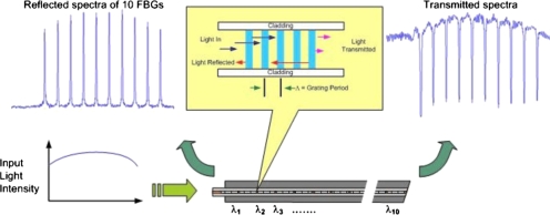
The use of fiber Bragg grating (FBG) technology13 enables the creation of multiple sensor locations along a single optical fiber. A FBG is a periodic refractive index (r.i.) perturbation formed in the core of an optical fiber, as shown in Fig. 1, created by exposure to an intense ultraviolet interference pattern. When a broad spectrum of light is launched into a fiber containing a set of FBGs, each reflects a slightly different narrow spectral band and transmits the remainder. This occurs because each FBG is designed with its unique periodicity of refractive index. Figure 1 illustrates a broad spectrum of light input to the fiber and a set of ten narrow reflection spectra from the ten FBGs.
Figure 1.
FBG principle: A broad spectrum of light is input to the fiber sensor. Narrow spectra of light are output in reflection from ten adjacent FBGs at 1548, 1551.5, 1555, 1558.5, 1562, 1565.5, 1569, 1572.5, 1576, and 1579.5 nm. Complimentary spectral minima occur in transmission. Spectral shifts are calibrated to temperature when subjected to heated tissue to obtain thermometry gradients. [For clarity of explanation only, the inset figure's aspect ratio between fiber core, cladding, etc. is not actual.]
Changes in stress and temperature modify the FBG periodicity as well as its refractive index which causes a spectral shift. As temperature increases, the reflected spectra are shifted toward longer wavelengths (to the right in Fig. 1) and when detected spectrometrically provide corresponding thermometry data.
About ten years ago Webb et al.14 reported the first concept demonstration of FBG based multipoint temperature profiling in in vivo trials in rabbits. Their implementation used a superluminescent diode (SLD) light source and an inexpensive charge-coupled device (CCD) spectrometer. Many limitations were also identified which required a solution before it could be considered for clinical trials. For instance, they noted a nonlinear response of some grating elements and an initial system calibration drift exceeding 10 °C, which required about 1 h of warm-up time to stabilize. They did not test their probe in the more commonly encountered microwave environment. Measurements were compared with an adjacent commercial flouroptic™ multisensor thermometry probe (Luxtron Corp, Santa Clara, CA) for only a few minutes during a heating-cooling cycle, noting differences of up to 3 °C. Their probe consisted of a single fiber glued into a 1 mm outer diameter surgical catheter. 1 mm holes were cut through a portion of the surgical catheter wall above each FBG location to allow for temperature equilibration between FBG and the surrounding tissue. The axial asymmetry introduced by these holes might result in a directional temperature sensitivity related to the axial rotation of the probe. Probe orientation was not investigated.
In this work we describe a stable, high accuracy, swept wavelength laser based FBG thermometry system and the development of an axially isotropic, ten-sensor, polymer coated FBG (PFBG) probe capable of measuring temperature gradients under simulated HT treatment conditions in tissue equivalent phantom.
EXPERIMENTAL METHOD AND MATERIALS
PFBG sensor probe
Several ten-sensor temperature probes based on FBG principles were developed using 125 μm diameter glass optical fibers (Fibercore Ltd., Southampton, United Kingdom, Type PS1500) that were hydrogenated and exposed to ultraviolet light patterns. Ten adjacent FBGs with periodicities distinct enough to result in spectra separated by 3.5 nm were fabricated. The designed r.i. periodicity of each FBG sensor is unique and for the ten-sensor probe, ranges from 0.5346 μm at FBG number 1 to 0.5454 μm for the tenth FBG. This fiber is then coated with a polymer which has a higher coefficient of thermal expansion than fused silica fiber to amplify the thermally induced stresses on it and create a PFBG sensor with high temperature sensitivity.
Optoelectronic system
To measure sensitively the spectral shifts in the reflected peaks of the PFBG probe, a semibroad spectrum light source is simulated by sweeping the very narrow band output from a diode laser over the spectral band of interest for a 1 s duration, which then takes another 1 s to return to its starting point. By synchronizing the detection time with the wavelength-time calibration of the swept laser, a high resolution spectrometric detection is obtained. An analog-to-digital conversion sampling rate of better than 200 kHz was implemented, which enabled a spectral resolution of better than 1 pm. LABVIEW® routines were developed to analyze data on a laptop computer.
Sensor calibration
Absolute temperature calibration was performed using a constant temperature circulating water bath, a NIST calibrated reference thermistor probe, and several BSD Bowman probes. A polymer coated fiber (PFBG) and an uncoated bare glass fiber with identical FBGs arrangement were placed in this such that they would be at depths similar to the reference and Bowman probes. The spectral shifts of each FBG in the probes were recorded as a function of temperature from 25 to 60 °C to obtain the wavelength change with temperature calibrations.
Performance under microwave hyperthermia of tissue equivalent phantom
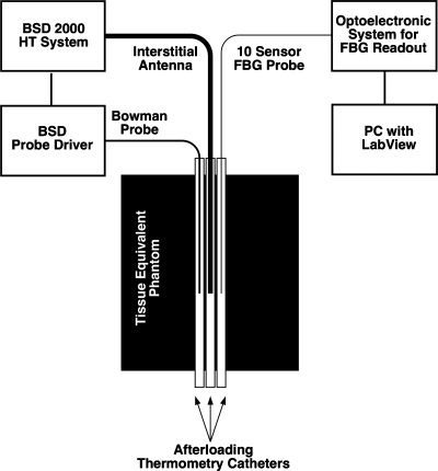
The PFBG probe was tested in an environment designed to approximate the microwave exposure which might be encountered during clinical hyperthermia treatments. A phantom, of dimensions 10×8×14 cm3, was prepared which approximated the dielectric properties of muscle tissue15 and three adjacent, parallel catheters were placed in it (Fig. 2). An interstitial microwave antenna with an embedded temperature sensor (Model BSD 201) was inserted into the central-most catheter as illustrated. Due to the axial (cylindrical) symmetry of the heating pattern produced by this type of dipole antenna, the temperature distributions along the two peripheral catheters, carrying the Bowman probe and the PFBG, will be nearly identical.
Figure 2.
Experimental setup for comparative temperature gradient measurement by optical fiber FBG sensors versus a mechanically scanned Bowman probe exposed to microwave hyperthermia.
The initial temperature distributions along the catheters were measured under ambient conditions of about 25 °C using the PFBG probe and the mechanically scanned Bowman probe.6 The Bowman probe is alternately pushed and pulled within its catheter and was programmed to map a distance of 15 cm in about 2 min. Simultaneous with the Bowman probe map, the temperature distribution along the symmetric PFBG probe bearing catheter was recorded.
A temperature control set point of 31 °C was then selected for the BSD microwave antenna’s embedded temperature control sensor and power applied. This roughly simulates the 6 °C gradient above 37 °C body ambient that a typical clinical HT therapy set point of 43 °C might produce. During microwave heating of the phantom, the thermal distributions in the two outer catheters were measured simultaneously at regular intervals.
RESULTS AND DISCUSSION
Sensor calibration and response time
The spectral shift data of the two FBG probes were measured in the water bath. The spectral shifts of the uncoated glass only probe were found to be nearly identical at 8.6±0.2 pm∕°C. The polymer coating provided a roughly threefold amplification of the temperature responses, the ten sensors responses in the PFBG probe were as follows: 26.7, 30.1, 29.8, 27.6, 23.9, 27.3, 25.3, 20.5, 21.5, and 16.5 pm∕°C (average value 23±7 pm∕°C), and they were not as homogeneous as those of the uncoated glass only probe. The temperature responses of the PFBG sensors and a thermocouple probe dropped into 65 °C water were measured. The rise time of the thermocouple to about 90% of its final value was roughly 2 s. The rise time of the PFBG sensors was roughly 5 s. The fall time of the TC is about 20 s versus about 10 s for the PFBG.
Temperature profiling in tissue phantom
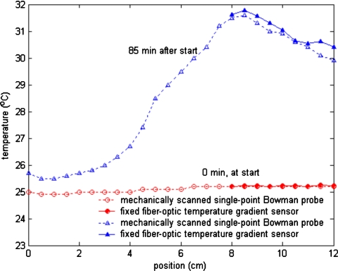
Temperature profiles measured adjacent to an interstitial microwave antenna that had been inserted in a tissue equivalent phantom are plotted in Fig. 3. About 10 W of microwave power was applied to the antenna. No self-heating artifacts were observed in the PFBG probe when the microwave power was on. The shape of the measured profiles closely tracked one another and the temperatures measured at equivalent positions along the antenna by the Bowman and PFBG probes generally differed by less than 0.5 °C. Figure 3 shows typical measured temperature profiles: One before power was applied to the antenna and another about 85 min later, after steady state conditions had been achieved with the microwave power on.
Figure 3.
Temperature profiles measured by PFBG and Bowman probes adjacent to an interstitial antenna in muscle equivalent phantom under steady state conditions: (a) Before microwave power was applied and (b) 85 min after power was applied to the antenna.
Stability of swept laser based FBG thermometry system
The FBG measuring system needs to accurately convert wavelength shifts to temperature by converting the pixels (e.g., in a CCD spectrometer) or time (in a tunable laser based system) to wavelength and then applying the temperature response calibration constant. To calibrate the measured time to the wavelength scale an industry standard solid state Fabry–Pérot etalon’s comblike reflection spectra are measured, which match the International Telecommunication Union or ITU grid spacing. This known ITU wavelength separation is then used to convert the time intervals of measured FBG spectra to wavelength.
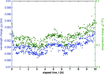
A reference etalon peak was tracked over 10 h to measure drift in the optoelectronic demodulation system by measuring the resulting wavelength and the corresponding temperature changes. These data are plotted in Fig. 4. The wavelength change was converted to the estimated temperature change shown in the right hand side y-axis assuming a nominal PFBG response of 28 pm∕°C. The maximum deviation observed was about 6 pm over 10 h, which corresponds to under 0.3 °C.
Figure 4.
The maximum drift of the swept laser based FBG thermometry system was less than 0.3 °C over a 10 h period. See text for further explanation.
The swept wavelength laser based FBG thermometry system described in this work has sufficient spectral bandwidth (100 nm) to accommodate several hundred hyperthermia thermometry locations. In comparison, SLD light sources have typically half the bandwidth. A larger spectral bandwidth enables a larger number of thermometry locations.
The temperature resolution of the system is proportional to the sampling rate. For example, an analog-to-digital conversion sampling rate of 200 kHz enables sub-pm resolution.16 In comparison, contemporary CCD spectrometers do not have the stability or pixel resolution required to detect 1 pm wavelength shifts. The larger relative deviation in temperature response among the sensors of the polymer coated PFBG (28±7 pm∕°C) versus the uncoated FBG (8.6±0.2 pm∕°C) probes is likely due to slight variations in the thickness of the manually applied polymer coating, which would have greater uniformity when using an automated process.
We found good agreement in absolute temperature readings between thermometry profiles made with the scanning Bowman probe and the PFBG temperature sensor.
CONCLUSIONS
We report results with a PFBG based, spatially resolving multipoint optical fiber temperature sensor, which has sufficient stability, precision, and accuracy for microwave hyperthermia thermometry. When subjected to microwave hyperthermia in a muscle equivalent phantom, the response is shown to closely follow that of a well established, microwave immune, single sensor commercial HT thermometry probe. The 0.5 mm diameter prototype probe consists of ten FBG locations at 5 mm intervals profiling a 5 cm overall length. There is nothing in the technology that prohibits more sensors or alternate lengths. A swept wavelength laser based readout system is shown to achieve 0.1 °C precision while maintaining a better than 0.5 °C stability over 10 h and an absolute measurement accuracy of ±0.25 °C. Furthermore, the 2 s response time is fast enough for automated feedback driven temperature control in hyperthermia applications.
This technology may now be considered mature enough for further investigation in in vivo clinical trials.
ACKNOWLEDGMENTS
This work is partially funded by Grant No. 1R43 CA78114 from the National Institutes of Health. The authors are thankful for the participation of Dr. Brent Ware, Dr. Alexander Berger, and Dr. Weijie Huang for sensor and system development.
References
- Astrahan M. A. et al. , “Heating characteristics of a helical microwave applicator for transurethral hyperthermia of benign prostatic hyperplasia,” Int. J. Hyperthermia 7(1), 141–155 (1991). 10.3109/02656739109004985 [DOI] [PubMed] [Google Scholar]
- Astrahan M. A., Ameye F. E., Oyen R., Willemen P., Baert L. V., and Petrovich Z., “Interstitial temperature measurements during transurethral microwave hyperthermia,” J. Urol. (Baltimore) 145(2), 304–308 (1991). [DOI] [PubMed] [Google Scholar]
- van der Zee J., González González D., van Rhoon G. C., van Dijk J. D. P., van Putten W. L. J., and Hart A. A. M., “Comparison of radiotherapy alone with radiotherapy plus hyperthermia in locally advanced pelvic tumours: A prospective, randomised, multicentre trial,” Lancet 355, 1119–1125 (2000). 10.1016/S0140-6736(00)02059-6 [DOI] [PubMed] [Google Scholar]
- Fessenden P., Lee E. R., and Samulski T. V., “Direct temperature measurement,” Cancer Res. 44(10 Suppl), 4799s–4804s (1984). [PubMed] [Google Scholar]
- van der Zee J., Peer-Valstar J. N., Rietveld P. J. M., de Graaf-Strkowska L., and van Rhoon G. C., “Practical limitations of interstitial thermometry during deep hyperthermia,” Int. J. Radiat. Oncol., Biol., Phys. 40(5), 1205–1212 (1998). 10.1016/S0360-3016(98)00008-X [DOI] [PubMed] [Google Scholar]
- F. A.Gibbs, Jr., “‘Thermal mapping’ in experimental cancer treatment with hyperthermia: Description and use of a semiautomatic system,” Int. J. Radiat. Oncol., Biol., Phys. 9, 1057–1063 (1983). [DOI] [PubMed] [Google Scholar]
- ter Haar G. R. and Dunn F., “Linear thermocouple arrays for in vivo observation of ultrasonic hyperthermia,” Br. J. Radiol. 57, 257–258 (1984). 10.1259/0007-1285-57-675-257 [DOI] [PubMed] [Google Scholar]
- Bowman R. R., “A probe for measuring temperature in radio-frequency heated material,” IEEE Trans. Microwave Theory Tech. 24, 43–45 (1976). 10.1109/TMTT.1976.1128763 [DOI] [Google Scholar]
- Christensen D. A., “A new nonperturbing temperature probe using semiconductor band edge shift,” J. Bioeng. 1, 541–545 (1977). [Google Scholar]
- Wickersheim K. and Alves R. B., “Recent advances in optical temperature measurement,” Ind. Res. Dev. 21, 82–89 (1979). [Google Scholar]
- Wolthuis R. A., Mitchell G. L., Saaski E., Hartl J. C., and Afromowitz M. A., “Development of medical pressure and temperature sensors employing optical spectrum modulation,” IEEE Trans. Biomed. Eng. 38(10), 974–981 (1991). 10.1109/10.88443 [DOI] [PubMed] [Google Scholar]
- Ryan T. P. et al. , “Design of an automated temperature mapping system for ultrasound or microwave hyperthermia,” J. Biomed. Eng. 13(4), 348–354 (1991). 10.1016/0141-5425(91)90118-Q [DOI] [PubMed] [Google Scholar]
- Mettz G., “Overview of fiber grating-based sensors,” Proc. SPIE 2838, 2–22 (1996). 10.1117/12.259786 [DOI] [Google Scholar]
- Webb D. J., Hathaway M. W., Jackson D. A., Jones S., Zhang L., and Bennion I., “First in-vivo trials of a fiber Bragg grating based temperature profiling system,” J. Biomed. Opt. 5, 45–50 (2000). 10.1117/1.429967 [DOI] [PubMed] [Google Scholar]
- Chou C. -K., Chen G. -W., Guy A. W., and Luk K. H., “Formulas for preparing phantom muscle tissue at various radiofrequencies,” Bioelectromagnetics (N.Y.) 5(4), 435–441 (1984). 10.1002/bem.2250050408 [DOI] [PubMed] [Google Scholar]
- Saxena I. and Mukamal H., “Apparatus and method for high resolution temperature measurement and for hyperthermia therapy,” U.S. Patent No. 7,717,618 (May 18, 2010).


