Abstract
The distorted Born iterative method (DBIM) computes iterative solutions to nonlinear inverse scattering problems through successive linear approximations. By decomposing the scattered field into a superposition of scattering by an inhomogeneous background and by a material perturbation, large or high-contrast variations in medium properties can be imaged through iterations that are each subject to the distorted Born approximation. However, the need to repeatedly compute forward solutions still imposes a very heavy computational burden. To ameliorate this problem, the multilevel fast multipole algorithm (MLFMA) has been applied as a forward solver within the DBIM. The MLFMA computes forward solutions in linear time for volumetric scatterers. The typically regular distribution and shape of scattering elements in the inverse scattering problem allow the method to take advantage of data redundancy and reduce the computational demands of the normally expensive MLFMA setup. Additional benefits are gained by employing Kaczmarz-like iterations, where partial measurements are used to accelerate convergence. Numerical results demonstrate both the efficiency of the forward solver and the successful application of the inverse method to imaging problems with dimensions in the neighborhood of ten wavelengths.
INTRODUCTION
Inverse scattering has received substantial research attention in the past three decades. Linear methods such as diffraction tomography1, 2, 3 seek rapid solutions under the assumption that the scatterer does not strongly contrast with the background medium, allowing simple inversion of the scattering operator. Quadratic methods4, 5 seek direct inversion of a second-order approximation to the scattering operator in an attempt to avoid local minima in the solution. Iterative linearized approximations seek a compromise between these two methods, overcoming the assumptions implicit in linear inverse scattering by representing the solution as a sequence of successive linear approximations.
The distorted Born iterative method (DBIM) has remained a powerful and popular linearized iterative inverse scattering algorithm since its inception nearly two decades ago.6 The method was originally applied to two-dimensional electromagnetic problems in free space, but has been implemented to solve acoustic problems7, 8, 9, 10 and electromagnetic problems in three dimensions.11, 12, 13, 14, 15 A distinct but mathematically equivalent method has been applied to two-dimensional acoustic problems.16, 17, 18 In addition, the distorted Rytov iterative method inverts the scattering problem in a manner analogous to the DBIM, but using the distorted Rytov approximation in place of the distorted Born approximation.19, 20
Inverse scattering algorithms in general, and the distorted Born iterative method in particular, have substantial promise in clinical ultrasound. The ability to reconstruct high-resolution, quantitative images of human tissues using acoustic waves may yield valuable diagnostic information that can help distinguish between normal and abnormal tissues.21, 22 Ultrasound is preferable to x-ray imaging because ultrasound waves are non-ionizing and do not easily damage tissue; non-ionizing electromagnetic radiation, with its relatively low frequency and very fast wave speed, has a much longer wavelength that degrades resolution. However, the computational complexity of inverse scattering algorithms has limited their use in clinical environments. Modern clinical ultrasound systems still employ b-scan imaging, which is much less computationally demanding but suffers from image speckle, the inability to provide sub-wavelength resolution, and the production of images that are inherently a combination of instrument and tissue characteristics. Current research on three-dimensional distorted Born imaging10, 14, 15, 23 typically employs forward solutions with computational scaling that are O(N log N) for N voxels, limiting the effectiveness for very large domains. Reported results do not appear to exceed 200, 000 unknowns. The solution of larger, more practical problems requires still greater efficiencies and careful implementations to push beyond this limit.
The fast multipole method (FMM) and its hierarchical extension, the multilevel fast multipole algorithm (MLFMA),24, 25, 26 offer a forward solver that scales linearly with the number of scattering elements.26 Furthermore, parallel implementations of the MLFMA have been developed27, 28, 29 that can efficiently employ tens or hundreds of processors for the solution of large-scale scattering problems. Although the MLFMA is known for high setup costs, these costs can be ameliorated by carefully exploiting the nature of the inverse problem. Additionally, any setup costs are amortized over many forward solutions in an iterative solver such as the DBIM.
This paper presents a novel hybrid of the distorted Born iterative method and the multilevel fast multipole algorithm designed to exploit the efficiencies of the forward solver. The resulting algorithm demonstrates linear computational scaling in both the number of imaging voxels and the number of transmissions used to measure the scattering domain; the computational efficiency remains independent of the number of receive angles. In addition, a Kaczmarz-like solution technique is proposed to more rapidly arrive at solutions for full-angle inverse scattering experiments. Although the Kaczmarz-like technique imposes serialization on the otherwise-parallel application of the Fréchet derivative of the scattering operator, problems of clinical relevance are large enough that the algorithm could not be fully parallelized even on large supercomputers. Hence, the Kaczmarz-like technique takes advantage of hardware limitations in an attempt to provide intermediate reconstruction information and improve convergence rates for the iterative inverse scattering procedure by updating more frequently the contrast image.
The remaining contents of this paper are organized as follows. First, the theory governing the inverse scattering problem is presented. Next, solution methods are described that employ the matrix-free distorted Born iterative method, the multilevel fast multipole algorithm, and a Kaczmarz-like technique. Following the method descriptions, simple numerical experiments are presented that, even on modest and readily-available hardware, demonstrate the efficient solution of inverse scattering problems. These examples study the behavior of the Kaczmarz-like technique and the performance of the method in the presence of noise. Finally, conclusions are drawn about the presented approach.
THEORY
Reconstruction of the acoustic parameters of arbitrary media is based on the inversion of the forward scattering problem. For the problem of interest, variations of density within a scattering medium will be neglected. The two acoustic parameters that govern wave propagation through the medium are therefore the real sound speed, c(r), and the attenuation slope, α(r), where r is the three-dimensional coordinate vector. If the attenuation slope α is defined in units of dB∕cm∕MHz, the complex wave number corresponding to these parameters is
| (1) |
where ω=2πf is the radian frequency of the time-harmonic pressure fields. A time dependence of e−iωt has been assumed and will be suppressed. The wave number k corresponds to an object contrast
| (2) |
which, in the presence of a source distribution S(r), admits a field φ=φi+φs that satisfies the wave equation
| (3) |
such that
for the homogeneous Green’s function
| (5) |
The distorted Born iterative method (DBIM) is motivated by expressing the field scattered by a medium relative to an inhomogeneous assumed background kb(r):
| (6) |
The field φb satisfies Eq. 3 in the presence of kb. If gb(r,r′) is the Green’s function describing the field due to a point source located at r′ in the presence of kb, the difference in fields may be expressed as
| (7) |
where Δφs=φs−φs,b is the difference between the field scattered by medium k and the field scattered by medium kb, and ΔO=O−Ob is the difference between the total and background contrast functions.
Inversion of the nonlinear expression 7 provides a correction ΔO to the assumed contrast Ob. To facilitate inversion, the contrast difference ΔO is assumed to be weakly scattering. Under this approximation, φ≈φb and Eq. 7 becomes the approximate differential scattering equation
| (8) |
The DBIM initially assumes a known background profile kb (in the absence of a priori information, kb=k0 is a suitable initial guess), and iteratively updates the assumed background with the computed update ΔO. With each iteration, the Green’s function gb must also be updated.
METHODS
The Fréchet derivative operator F is defined as
| (9) |
This operator relates changes in the background scatterer to changes in the observed scattered field. For numerical inversion of the differential scattering of Eq. 8, the distorted Born method computes a solution ΔO from a series of products of F with search functions computed through an iterative process.
In realistic measurement scenarios, the range of the operator (the locations at which the scattered field is measured) and the domain of the operator (the support of the scatterer) do not coincide and have different dimensionalities. The discretized Fréchet derivative operator is therefore not square. To overcome this issue, one of two alternative equations can be solved iteratively to yield a solution to Eq. 8:
When the measurement configuration results in an overdetermined system (when the discrete form of the equation contains more measurement samples than samples of the scattering contrast), the first form 10a is appropriate and will solve the equation in the least-squares sense. When the measurement configuration results in an underdetermined system, the second form 10b is appropriate and produces the minimum-norm solution by constraining the solution to the space spanned by the columns of F†.
Matrix-free inversion
A formulation of the DBIM has been previously developed30 to invert the Fréchet derivative operator in the differential scattering Eq. 8 without the need to construct an explicit matrix equation or to compute Green’s functions for inhomogeneous background media. In typical formulations (such as that of Ref. 11), application of the Fréchet derivative and its adjoint requires knowledge of the Green’s function in the presence of an assumed background. This is accomplished either by precomputing and storing the fields induced in the background by each of the transmitters and receivers or by computing these quantities on demand. While the alternative formulation does not avoid the need to compute fields induced by each of the transmitters, there is no need to compute fields induced by each of the receivers individually. This makes the inverse scattering problem much more efficient, especially when many background updates (and, therefore, updates to the Fréchet derivative) are required.
The term Δφs in Eq. 8 is the total field in the presence of kb due to a source distribution J=ΔOφb. The field φb is computed using a fast forward solver for an assumed background Ob, allowing iterative inversion of the differential scattering Eq. 8 to proceed efficiently. As a side effect of this formulation, the Green’s function gb does not need to be explicitly calculated. With the source distribution J, the Fréchet derivative may be expressed as
| (11) |
where φJ(r′) is the field in the presence of Ob due to the source distribution J:
| (12) |
Thus, computing the Fréchet derivative requires two calls to a fast forward solver: one to compute φb, and another to find φJ. In a similar fashion, the adjoint Fréchet derivative may be expressed as
| (13) |
where [⋅]* denotes complex conjugation, VT is the space in which transmissions are defined, and φY is the field induced in Ob by a source distribution Y excited within the receiver space VR:
| (14) |
Observe that, in the definition of the adjoint Fréchet derivative 13, the quantities φb(r) and φY(r) are implicit functions of the transmitter location rT and are, therefore, not constant in the integrand. A more thorough derivation of this matrix-free formulation of the Fréchet derivative and adjoint Fréchet derivative operators is presented in Ref. 30.
Application of the multilevel fast multipole algorithm
The Fréchet derivative and adjoint Fréchet derivative operators may be computed in a matrix-free fashion using the expressions 11, 13, respectively, but the corresponding solutions 12, 14 required to implement these formulations must take advantage of fast solvers if the overall method is to be efficient. The fast multipole method (FMM) and the multilevel fast multipole algorithm (MLFMA)26, 31 provide the requisite efficiency, offering evaluation of the scattering operator in O(N) time for N unknowns for three-dimensional, volume-filling scatterers.26 In addition, the relatively high setup overhead associated with the MLFMA can be amortized over the repeated forward solutions required in the distorted Born iterative method.
Since the solutions of the forward problems 12, 14 must be computed for each transmit angle, and the solution for unique transmit angles are independent, the evaluation of the Fréchet derivative operator and its adjoint are embarrassingly parallel. Each of the fields φb due to a distinct transmit angle may be produced in parallel with no interprocess communication or synchronization overhead. Likewise, φJ and φY can be computed with no communication or synchronization demands. With each of these three fields available for all transmit angles, only the adjoint Fréchet derivative operator requires communication or synchronization to perform the final integration in Eq. 13. As detailed for two-dimensional problems,30 the distorted Born iterative method distributed in this fashion scales almost ideally up to T processors when there are T unique transmit angles in an inverse scattering experiment. However, the algorithm does not scale above T processors.
A parallel MLFMA can alleviate these scaling issues. Several researchers have investigated parallel implementations of the MLFMA, with problems involving tens of millions of unknowns scaling well on tens of processors.28, 29, 32, 33, 34 An additional study has shown excellent scaling of the MLFMA for more than 100 processors.27 In addition, by assigning unique transmit angles to distinct groups of processors instead of single processors, each forward scattering solution can be computed independently with a parallel MLFMA. This allows a significant increase in the number of processors that may be employed to solve the inverse scattering problem, taking advantage of the low overhead associated with the evaluation of independent forward solutions where appropriate.
Redundancy in the fast multipole method
In the inverse problem, the material properties of the scattering medium are not known a priori. Therefore, seeking an optimal covering of the scattering region (using, e.g., tetrahedral scattering elements) offers no benefit. Cubic scattering elements arranged in a regular grid offer several advantages in the forward problem that are leveraged in the results presented here. Minor benefits include a reduced memory footprint for geometric descriptions, more straightforward meshing of the scattering domain, and a resulting contrast image that is easy to visualize.
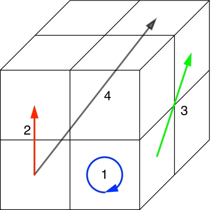
The principal benefit of a regular, cubic arrangement of scatterers is the redundancy that may be exploited to improve computational efficiency. When scatterers are of equal, cubic dimensions and regularly spaced within a grid, the interactions between scatterers obey a pattern. The translational invariance of the Green’s function and symmetry of the problem means, for example, that the value of the Green’s function is the same whenever the source and receiving elements are separated by a constant number of grid spaces along any dimension. This value does not depend on the position of these two elements in the global grid. For example, in a cubic grid of 8 elements in a 2×2×2 arrangement, there are 64 interactions, only four of which are unique:
-
1.
The interaction of any element with itself;
-
2.
The interaction of any two elements separated by one grid space in exactly one dimension;
-
3.
The interaction of any two elements separated by one grid space in exactly two dimensions; and
-
4.
The interaction of any two elements separated by one grid space in exactly three dimensions.
An example of each of these interactions is shown in Fig. 1. While the MLFMA requires knowledge of these 64 interactions because the proximity of the elements renders multipole expansion inaccurate, only four evaluations of integrals of the Green’s function need to be calculated to represent all interactions. Since these interactions are typically precomputed rather than computed on demand, reducing such computations reduces the setup time of the MLFMA. Furthermore, since precomputation requires storage of these values, the overall memory footprint of the algorithm is reduced. The memory associated with direct interactions in this simple example is reduced by a factor of 16.
Figure 1.
Representative interactions in a grid of 2×2×2 scattering elements. There are only four unique types of interactions in this group of unknowns.
This redundant information is not restricted to evaluation of direct interactions. The multilevel fast multipole algorithm requires the determination of outgoing and incoming far-field patterns for scattering elements, defined respectively as26
The outgoing pattern provides a representation of the field radiated by an induced source at the scattering element as a directional distribution of plane-wave amplitudes emanating from an arbitrary center c. Conversely, the incoming pattern serves to “focus” incoming waves, scaling the amplitudes of plane waves converging on an arbitrary center c before the waves are summed to represent the field induced in a target basis function. The unit vector , defined over the unit sphere, characterizes the angular dependence of the pattern associated with the particular element. The basis function f characterizes the field over the support of the scattering element. In a regular, cubic arrangement of scattering elements, the basis functions f associated with each element are identical, and the integrals 15 are identical except for the translationally invariant offset r−c. If every finest-level MLFMA group is described by an identical but translated grid structure, the collection of incoming and outgoing patterns for a single group may be recycled to represent the patterns for every other group. The need to compute only one set of patterns, rather than one for every group, greatly reduces the setup overhead of the MLFMA.
Fast superposition of multiple sources
The adjoint Fréchet derivative operator correlates fields induced by transmitters with fields produced by simultaneous excitation of all receivers. To find the field produced by this simultaneous excitation of all receivers, an incident field must be computed. A continuous distribution of plane waves originating from directions relative to a center c0 and with amplitudes produces an incident field φi,f on a testing function f given by
| (16) |
where Ω is the unit sphere. To evaluate this field directly for N distinct testing functions involves O(NR) operations, where R is the number of samples of the space Ω. When R and N are large, simply generating the incident field can be a costly operation, especially since this calculation needs to be computed once for every transmit angle.
In analogy with the fast computation of scattered fields first described in Ref. 35, the MLFMA can be used to accelerate computation of Eq. 16 in a way that is approximately independent of the number of receivers. The disaggregation procedure of the MLFMA distributes an arbitrary distribution of incoming plane waves centered about c0 to a testing function f within the computational domain by computing
| (17) |
where L is the maximum MLFMA level and cl represents the center of the MLFMA group at level l containing the testing function f. The operators Fl represent lowpass filtering of the plane-wave distribution P for MLFMA level l. In their discrete forms, the lowpass filters also reduce the sampling rate of P to allow accurate but more efficient evaluation of the integrals of the filtered distribution.
By letting and changing the variable , the disaggregation operation 17 may be written
| (18) |
in which the filtering operators Fl have been composited and applied to to yield (after canceling the complex exponentials) a lowpass-filtered approximation . The accuracy of the approximation 18 to the true incident field [Eq. 16] depends on the filter cutoff. If the cutoff is chosen according to the excess bandwidth formula with the same parameters used for other MLFMA interactions, the error of the incident field approximation will not exceed the error of the forward solver calculations.
The successive filtering, resampling and shifting operations of the MLFMA disaggregation procedure occur in O(N) time for N unknowns. If the incident distribution A is not sampled on a grid coincident with that required to represent incoming far-field patterns for the coarsest MLFMA level, the distribution must be interpolated. The interpolation may be performed in O(R) time when the distribution is known at R points. Hence, for N unknowns and R=o(N) receivers (as is the case in typical measurement scenarios), the disaggregation method for computing the incident field will have overall complexity O(N+R)=O(N). This is much more efficient than direct computation.
Minimizing transmission angles
The DBIM formulated using the MLFMA for fast superposition of multiple sources and fast computation of scattered fields exhibits linear scaling dependence on the number of transmit angles and independence from the number of receive angles used to image a scattering domain. In the absence of any hardware concerns that may impose constraints on the measurement configuration, the cost of a DBIM iteration that seeks to maintain a constant total number of measurements will benefit from reducing the number of transmit angles while compensating with an increased number of receive angles. Attempting to reduce the number of transmitters while retaining image quality requires careful consideration. Extreme attempts to limit the number of transmit angles (for example, employing only a single transmission) may fail to insonify portions of the scatterer, resulting in shadowing effects that cannot be overcome. However, even when multiple transmissions are employed, another issue can affect reconstruction quality.
The field scattered by a domain of fixed size has an approximately limited harmonic bandwidth that can be estimated according to the excess bandwidth formula
| (19) |
where k is the wave number, a is the radius of the smallest sphere enclosing the object and β depends on the accuracy of the approximation.26, 36 For a field with harmonic bandwidth L, the field may be completely described with L polar angular samples and 2L azimuthal angular samples. Eliminating duplicate samples at the poles, the total number of samples required to represent the scattered field without aliasing is therefore Ns=2L(L−2)+2.
If the number of receivers is increased beyond the limit specified by the excess bandwidth formula 19, receivers will oversample the scattered field and contribute redundant information to the inverse problem. Increasing the number of receive angles beyond the oversampling limit while decreasing the number of transmit angles to improve performance will result in a loss of unique transmission information without introducing unique reception information. This loss of unique information will result in degraded reconstructions.
A Kaczmarz-like method
The Kaczmarz method37 is an iterative technique to invert a system of equations without manipulating the entire system at each iteration. If the system represents an m×n matrix equation with n≤m, the Kaczmarz method seeks an iterative solution
| (20) |
where xk is the approximate solution for the k-th iteration, i=k mod m, bi is the i-th element of b, and Ai is the transposed i-th row of . The sequence xk converges to the true solution x provided that is invertible. Direct application of the method requires complete knowledge of matrix . Therefore, direct application of the Kaczmarz method to the matrix-free DBIM is not appropriate.
When there are not enough parallel processors available to distribute solutions for independent transmit angles, performance of the DBIM can be improved with a Kaczmarz-like, round-robin scheme. Rather than attempt to invert the entire Fréchet derivative matrix to arrive at an update to the background contrast, the round-robin scheme considers only the portion of the Fréchet derivative matrix constrained to a limited number of insonification angles. The constrained Fréchet derivative problem will be severely underdetermined. In this case, the method 10b is used to provide a solution with minimum norm.
When a contrast update has been obtained, the partial Fréchet derivative constrained to a different set of insonification angles is inverted for an additional update. The process then repeats to further refine the solution until all transmit angles have been considered in sequence. The cost of applying the partial Fréchet derivative for a single transmit angle involves exactly two forward solutions, while application of its adjoint requires another forward solution. Hence, a full sequence of contrast updates using the round-robin technique for every transmission is no more expensive than a single DBIM iteration using the full Fréchet derivative, since successive applications of partial Fréchet derivatives and their adjoints for every set of insonification angles involves as many forward solutions as a single application of the full Fréchet derivative and its adjoint.
The round-robin scheme is distinct from the classical Kaczmarz method because the Kaczmarz method assumes the linear operator remains constant during iterations. In the round-robin technique, updates in the solution at each step are matched with a change in the Fréchet derivative operator being inverted. This key difference can help accelerate convergence of the imaging process because each partial solution takes advantage of information about the scatterer obtained from previous partial solutions. Such intermediate information is unavailable in DBIM inversions that employ the full Fréchet derivative to compute each update. However, the round-robin technique is only efficient when application of the Fréchet derivative and its adjoint can be performed using the previously described technique that avoids the need to explicitly construct Green’s functions for the constantly changing, inhomogeneous background.
In analogy with the frequency hopping employed to solve multiple-frequency imaging problems,8, 9, 15, 20, 30, 38, 39 the round-robin technique attempts to avoid local minima associated with the solution of a single, restricted inverse problem (e.g., involving a single imaging frequency and a limited set of transmit angles) by using a previously obtained solution as a starting guess for a subsequent inversion. If local minima associated with distinct transmit angles do not coincide, a solution stagnating in a local minimum for one transmit angle may move away from the local minimum and toward the global minimum when the transmit angle is shifted.
Regularization
Regularization of the inverse problem is important because the problem is ill posed in the sense of Hadamard. The classical Tikhonov regularization of the inverse scattering problem 8 seeks a solution to the modified least-squares equation
| (21) |
where α is a regularization parameter. The solution to this equation minimizes the modified cost functional
| (22) |
Hence, the regularization parameter α mitigates the effect of small singular values of F on the solution and imposes a penalty on large variations in ΔO.
A strategy for the selection of the regularization parameter α was presented in Refs. 9, 10 that uses the expression
| (23) |
where σ0 is the dominant singular value of the Fréchet derivative and may be estimated using power iteration. The relative residual error (RRE) is given by
| (24) |
in which VR and VT represent, respectively, the receiver and transmitter measurement spaces, and the scattered field φs and field error Δφs have been expressed as functions of both the transmit and receive angles. The choice of regularization parameter 23 was motivated by spectral analysis of the Fréchet derivative operator for two-dimensional scattering geometries.8
When the round-robin technique is employed, the importance of regularization is diminished. The underdetermined system of equations resulting from inversion of the Fréchet derivative operator of a limited number of transmit angles is inverted using the minimum-norm technique [Eq. 10b], which automatically imposes a penalty on large variations in the solution ΔO. However, when noise is present, regularization using the above strategy [Eq. 23] can mitigate the effects of noise by suppressing error in the Fréchet derivative operator.
NUMERICAL RESULTS
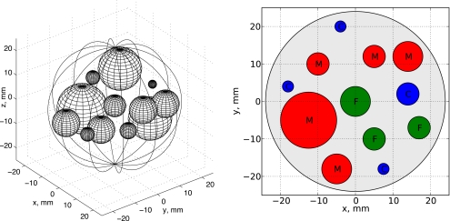
A single scattering configuration will be the basis for numerical experiments involving the distorted Born iterative method. The scatterer, shown in Fig. 2, involves twelve spheres of various sizes and acoustic properties embedded in a larger reference sphere. The properties of the spheres are designed to mimic the human tissues shown in Table 1. The reference sphere is immersed in water, which is assumed to be of infinite extent. The specific parameters describing each sphere are listed in Table 2. Density variations were not considered for these experiments, although the effect of density variations on distorted Born imaging has been examined in Ref. 9.
Figure 2.
The reference scattering geometry used for inverse scattering experiments. At left, a three-dimensional view of the 12 scattering spheres. At right, a cross section of the geometry in the z=0 plane showing the tissue type assignments: “M” for muscle, “F” for fat, and “C” for connective tissue.
Table 1.
Material properties of spheres designed to mimic human tissue.
| Tissue | Sound speed (m∕s) | Absorption (dB∕cm MHz) |
|---|---|---|
| Water | 1509.0 | 0.00 |
| Fat | 1478.0 | 0.52 |
| Muscle | 1547.0 | 0.91 |
| Skin | 1613.0 | 1.61 |
| Reference | 1570.0 | 0.30 |
Table 2.
Characteristics of the spheres in the tissue-mimicking phantom.
| Radius (mm) | Center (mm) | Tissue | ||
|---|---|---|---|---|
| x | y | z | ||
| 4.0 | 0.0 | 0.0 | 0.0 | Fat |
| 5.0 | 14.0 | 2.0 | 4.0 | Skin |
| 5.0 | 5.0 | −10.0 | −4.0 | Fat |
| 3.0 | 17.0 | −7.0 | 0.0 | Fat |
| 7.8 | −10.0 | 10.0 | 7.2 | Muscle |
| 7.8 | 5.0 | 12.0 | −7.2 | Muscle |
| 5.0 | 14.0 | 12.0 | 3.0 | Muscle |
| 5.0 | −5.0 | −18.0 | −3.0 | Skin |
| 2.5 | 7.5 | −18.0 | −2.0 | Skin |
| 1.5 | −4.0 | 20.0 | 0.0 | Skin |
| 2.5 | −18.0 | 4.0 | 2.0 | Skin |
| 9.1 | −12.5 | −5.0 | −5.2 | Muscle |
The computer hardware used to perform imaging simulations consists of single workstation with 16 GB or random-access memory and two 2.4-GHz AMD Opteron processors with two CPU cores in each package. The forward and inverse scattering implementation was threaded to take advantage of all processing cores without the need for message passing. To generate the synthetic scattering data used for inversion, an integral equation solver similar to that employed in the inverse solver was used.
Asymptotic scaling
Scaling of the DBIM with an MLFMA forward solver was tested by independently varying the number of voxels in the reconstruction domain and the number of transmissions used to image the domain. To measure performance with a variable number of voxels, the scattering phantom was insonified by 100-kHz plane waves incident from two directions in the θ=90° plane (ϕ=0° and ϕ=180°). Far-field scattering measurements were collected on an equi-angular grid composed of 64 polar and 128 azimuthal samples over the unit sphere. The imaging domain was assumed to be a cube with edge lengths of 4λ0, where λ0 is the wavelength in water. This domain is approximately 25% larger than the scatterer radius in each dimension. The number of voxels was varied from 16 to 128 per dimension. A single DBIM iteration was performed using two round-robin steps of a single transmission each.
The performance of the DBIM with a variable number of transmissions was measured assuming an approximately constant total number of measurements and a constant number of voxels. As in the variable voxel experiment, the scatterer was insonified with 100-kHz plane waves. The cubic imaging domain had an edge length of 4λ0 and was sampled with a 32×32×32 voxel grid. Transmissions were defined on an equi-angular grid with Tθ polar samples and Tϕ=2Tθ azimuthal samples over the unit sphere, with Tθ ranging between 2 and 12 directions. The field was sampled on an equi-angular grid with Rθ polar samples and Rϕ=2Rθ azimuthal samples over the unit sphere, with Rθ chosen according to the formula
| (25) |
where N=32 is the number of voxels per dimension and N3 is the total number of voxels. Hence, the total number of measurements is approximately twice the number of voxels.
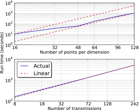
The per-iteration run times for both a variable number of voxels and a variable number of transmit angles are shown in Fig. 3. As expected, the inversion is approximately linear in the number of voxels, with some deviation from linear scaling for small domains (where MLFMA setup time is significant compared to inversion time) and slight variations as the number of voxels requires nonuniform filling of MLFMA groups and, hence, suboptimal MLFMA trees. Ideal linear scaling is shown to bound the scaling of the inversion as the number of voxels increases. For a variable number of transmissions, the actual scaling is much closer to ideal linear scaling. Because the MLFMA aggregation and disaggregation procedures have been used, respectively, to compute far-field scattering and incident fields due to multiple plane waves, the scaling in the bottom panel of Fig. 3 was virtually independent of the number of receive angles, which varied inversely with the number of transmit angles.
Figure 3.
Run times for DBIM inversion with (i) a fixed number of measurements but a variable number of voxels (top) and (ii) a fixed number of voxels but a variable number of transmit angles (bottom).
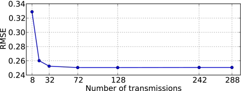
The inversions involving a variable number of transmit angles were run until the RRE 24 fell below 1%. As shown in Fig. 4, the corresponding root-mean-square error (RMSE) between the reconstructed image O and an ideal reference image Or, defined as
| (26) |
fell sharply to a floor of 25.1% as the number of transmit angles was increased above 32. The number of iterations required to obtain a convergent solution decreased only slightly, from 9 iterations for Tθ≤4 and 8 iterations otherwise.
Figure 4.
Root-mean-squared error, as a function of the number of transmit angles, of the earliest contrast reconstruction corresponding to a relative residual error below 1%.
The increase in final RMSE in Fig. 4 for measurement configurations involving fewer than 72 transmit angles is explained by the degrading effect of oversampling received fields to ensure a constant number of total measurements. The excess bandwidth formula 19 predicts a maximum possible harmonic bandwidth L≈30 for two-digit accuracy. For this bandwidth, attempts to keep the number of measurements constant resulted in oversampled received fields for configurations involving fewer than 72 transmit angles. The resulting loss of unique scattering information resulted in increased reconstruction error.
The round-robin technique
Reconstruction tests involving the round-robin technique were performed with 300-kHz insonification of the phantom depicted in Fig. 2, which had a radius of 4.8λ0 at the operating frequency. The reconstruction domain was cubic with an edge length of 12.8λ0 and was centered at the center of the reference sphere. The domain was divided into a 64×64×64-voxel grid. Plane-wave transmissions were simulated from an equi-angular grid on the unit sphere with Tθ=6 and Tϕ=12, the smallest number of transmissions that produced a convergent RMSE of 25.1% in the scaling experiments described above. To ensure that the overall measurement scheme was overdetermined by a factor close to two, the scattered field was sampled on an equi-angular grid with Rθ=60 and Rϕ=120. This scheme does not oversample the fields, which have an estimated maximum harmonic bandwidth L≈80.
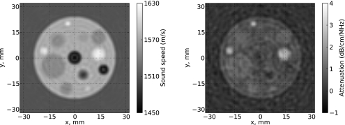
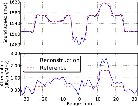
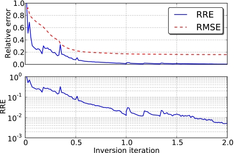
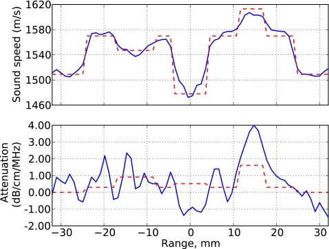
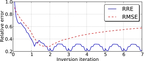
Reconstruction experiments were first conducted with a single transmit angle per round-robin step. The resulting systems corresponding to each step were severely underdetermined, so the solution was sought in the minimum-norm sense [Eq. 10b]. Because minimal variations are favored in the minimum-norm solution, regularization was not applied to the inversion procedure. Two entire iterations (comprising a total of 144 round-robin steps) were required to obtain an RRE below 1%, resulting in a final RMSE of 16.0%. Representative z=0 slices of the reconstructed sound speed and attenuation slope are shown in Fig. 5, while a comparison between the reconstruction and the reference image along the y=z=0 line is shown in Fig. 6. The convergence history of the inversion is shown in Fig. 7.
Figure 5.
Sound-speed (left) and attenuation slope (right) reconstructions, in the z=0 plane, of a phantom using the round-robin technique to invert scattering from 300-kHz plane waves incident from 72 directions.
Figure 6.
Sound-speed (left) and attenuation slope (right) reconstructions, along the y=z=0 line, of a phantom using the round-robin technique to invert scattering from 300-kHz plane waves incident from 72 directions.
Figure 7.
The root-mean-square error and corresponding relative residual error for iterative reconstruction of a scattering phantom at 300 kHz (top). The round-robin technique was employed to yield reconstruction results and error measurements at fractional iterations. The relative residual error is also shown on a log scale to provide more detail in the low-error limit (bottom).
As Figs. 56 show, reconstructions of sound speed are more accurate than reconstructions of attenuation. This phenomenon is observed because any finite measurement scheme fails to collect all information contained in the scattered field. Finite apertures will not capture all outward-radiating scattered waves, while evanescent waves will never be detected with far-field measurements. This missing information manifests as spurious attenuation in the reconstruction, which absorbs energy that cannot be measured.
An attempt to compare the round-robin technique to standard DBIM inversion was performed using the choice of regularization parameter dictated by Eq. 23. However, after six iterations, the solution began to diverge from a minimum RRE of 37.7% and a minimum RMSE of 52.3%. While an improved selection of the regularization parameter (specifically, a slower rate of decrease) can help to combat the divergence, this would tend to slow convergence of the problem and require more iterations to obtain a final solution. Furthermore, no selection of regularization parameters was found to provide a lower RMSE corresponding to a 1% RRE than that of the round-robin solution. Thus, for this example, the round-robin technique was at least three times faster at obtaining a convergent reconstruction than the traditional DBIM, while paying no penalty in the quality of the reconstruction.
Experiments were also conducted with multiple transmissions per round-robin step. The number of transmissions per step was increased from 1 to 24, with no appreciable difference in final reconstruction quality for an RRE tolerance of 1%. However, as the number of transmissions per step was increased, the total number of contrast updates per overall DBIM inversion decreased, which resulted in increased iteration counts to obtain the desired 1% RRE. In the worst case, using 24 transmissions per round-robin steps requires 4 full DBIM iterations, while only two iterations were required to obtain the same RRE for a round-robin solution with 1 transmissions per step. Multiple transmissions were grouped by consecutive indices, with indexing starting at the minimum polar and azimuthal transmit angles and increasing in raster order, first through azimuthal angles and then through polar angles. No attempt was made to optimize the choice of grouped transmit angles.
Imaging in the presence of noise
Noisy imaging experiments were conducted by adding a Gaussian-distributed noise to the simulated measurements. The peak signal-to-noise ratio (PSNR) for single-transmission measurements collected at R=RθRϕ locations , where Ω is the unit sphere, is defined to be
| (27) |
in which the noise , the noisy measurement is φs,N and the ideal measurement is φs. The noise E is assumed to be independent of and to have zero mean.
The parameters of the previous imaging experiment were used for the noisy imaging simulation. Plane-wave transmissions oscillating at 300-kHz were simulated from an equiangular grid with Tθ=6 and Tϕ=12. The scattered field was sampled on an equi-angular grid with Rθ=60 and Rϕ=120. The standard deviation of the Gaussian noise was chosen such that the PSNR was 40 dB. The corresponding total signal-to-noise ratio (SNR) was, averaged over all transmissions,
| (28) |
which corresponds to 28% error due to noise. Imaging was performed on a 64×64×64-voxel domain with overall edge length of 12.8λ0.
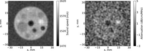
A reconstruction was attempted using the round-robin technique with a single transmission per step. Since the simulated noise contributed an uncertainty to the scattered field of approximately 28%, the convergence criterion was an RRE less than 28%. This was attained after two overall DBIM iterations, with an RRE of 21.2%. The reconstruction profile in the z=0 plane is shown in Fig. 8, while the profile along the y=z=0 line is compared to an ideal reference image in Fig. 9. Although the sound speed is faithfully reconstructed, there is significant error in the attenuation slope. As discussed above, this error may be attributed to non-ideal measurement schemes that fail to capture all information of the scattered field. In addition, artificial variations in measured scattered energy contributed by noise may be compensated by the addition of spurious positive and negative attenuation. Round-robin reconstructions involving multiple transmissions per step did not affect the convergence rate and had no substantial impact on the RRE and RMSE of the convergent solution.
Figure 8.
Sound-speed (left) and attenuation slope (right) reconstructions, in the z=0 plane, of a phantom using the round-robin technique to invert noisy scattering from 300-kHz plane waves incident from 72 directions.
Figure 9.
Sound-speed (left) and attenuation slope (right) reconstructions, along the y=z=0 line, of a phantom using the round-robin technique to invert noisy scattering from 300-kHz plane waves incident from 72 directions.
The convergence history of the noisy reconstruction is shown in Fig. 10. The regularization strategy in Eq. 23 was used to mitigate the sensitivity of the reconstruction process to noisy data. During the second iteration, the regularization parameter was α≈0.03|σ0|2, which was sufficient to allow the RMSE to converge to 28.2%. However, additional iterations were computed with α≈0.005|σ0|2, causing the contrast solution to diverge while the RRE did not increase. This illustrates the sensitivity of noisy DBIM reconstructions to a termination strategy and to selection of the regularization parameter.
Figure 10.
Relative residual error and root-mean-square error for a noisy reconstruction.
CONCLUSION
An implementation of the distorted Born iterative method was presented that incorporates the multilevel fast multipole algorithm for efficient solutions. The MLFMA scales linearly with the number of scattering elements, providing excellent scalability for computationally intensive, linearized inverse scattering problems. Although the MLFMA suffers from relatively high setup costs, a careful implementation and aggressive reduction of redundant preliminary calculations both reduced the setup time and amortized the cost over repeated applications of the forward solver. In addition, a Kaczmarz-like, round-robin technique was presented to accelerate convergence and offer intermediate results useful for visualization and monitoring while the full imaging process is still underway. Numerical results demonstrated the effectiveness of this technique and the linear scaling of the inverse scattering algorithm in both the number of voxels and the number of transmit angles.
ACKNOWLEDGMENTS
This work was partially funded by AFOSR grant F9550-04-1-0326 and NIH grants 9 R01 EB00280-09 and 1 R01 EB009692-01.
References
- Devaney A. J., “A filtered backpropagation algorithm for diffraction tomography,” Ultrason. Imaging 4, 336–350 (1982). 10.1016/0161-7346(82)90017-7 [DOI] [PubMed] [Google Scholar]
- Slaney M., Kak A. C., and Larsen L. E., “Limitations of imaging with first-order diffraction tomography,” IEEE Trans. Microwave Theory Tech. 32, 860–874 (1984). 10.1109/TMTT.1984.1132783 [DOI] [Google Scholar]
- Borup D. T., Johnson S. A., Kim W. W., and Berggren M. J., “Nonperturbative diffraction tomography via Gauss-Newton iteration applied to the scattering integral equation,” Ultrason. Imaging 14, 69–85 (1992). 10.1016/0161-7346(92)90073-5 [DOI] [PubMed] [Google Scholar]
- Pierri R. and Leone G., “Inverse scattering of dielectric cylinders by a second-order Born approximation,” IEEE Trans. Geosci. Remote Sens. 37, 374–382 (1999). 10.1109/36.739072 [DOI] [Google Scholar]
- Pierri R., Leone G., and Persico R., “Second-order iterative approach to inverse scattering: Numerical results,” J. Opt. Soc. Am. A 17, 874–880 (2000). 10.1364/JOSAA.17.000874 [DOI] [PubMed] [Google Scholar]
- Chew W. C. and Wang Y. M., “Reconstruction of two-dimensional permittivity distribution using the distorted Born iterative method,” IEEE Trans. Med. Imaging 9, 218–225 (1990). 10.1109/42.56334 [DOI] [PubMed] [Google Scholar]
- Lu C. C., Lin J. H., Chew W. C., and Otto G. P., “Image reconstruction with acoustic measurement using distorted Born iteration method,” Ultrason. Imaging 18, 140–156 (1996). 10.1006/uimg.1996.0008 [DOI] [PubMed] [Google Scholar]
- Lavarello R. and Oelze M., “A study on the reconstruction of moderate contrast targets using the distorted Born iterative method,” IEEE Trans. Ultrason. Ferroelectr. Freq. Control 55, 112–124 (2008). [DOI] [PubMed] [Google Scholar]
- Lavarello R. and Oelze M., “Density imaging using inverse scattering,” J. Acoust. Soc. Am. 125, 793–802 (2009). 10.1121/1.3050249 [DOI] [PubMed] [Google Scholar]
- Lavarello R. J. and Oelze M. L., “Tomographic reconsruction of three-dimensional volumes using the distorted Born iterative method,” IEEE Trans. Med. Imaging 28, 1643–1653 (2009). 10.1109/TMI.2009.2026274 [DOI] [PubMed] [Google Scholar]
- Cui T. J., Chew W. C., Aydiner A. A., and Chen S., “Inverse scattering of two-dimensional dielectric objects buried in a lossy earth using the distorted Born iterative method,” IEEE Trans. Geosci. Remote Sens. 39, 339–346 (2001). 10.1109/36.905242 [DOI] [Google Scholar]
- Wang G. L., Chew W. C., Cui T. J., Aydiner A. A., Wright D. L., and Smith D. V., “3D near-to-surface conductivity reconstruction by inversion of VETEM data using the distorted Born iterative method,” Inverse Probl. 20, S195–S216 (2004). 10.1088/0266-5611/20/6/S12 [DOI] [Google Scholar]
- Li F., Liu Q. H., and Song L. -P., “Three-dimensional reconstruction of objects buried in layered media using Born and distorted Born iterative methods,” IEEE Geosci. Remote Sens. Lett. 1, 107–111 (2004). 10.1109/LGRS.2004.826562 [DOI] [Google Scholar]
- Yu C., Yuan M., Stang J., Bresslour E., George R. T., Ybarra G. A., Joines W. T., and Liu Q. H., “Active microwave imaging II: 3-D system prototype and image reconstruction from experimental data,” IEEE Trans. Microwave Theory Tech. 56, 991–1000 (2008). 10.1109/TMTT.2008.919661 [DOI] [Google Scholar]
- Yu C., Yuan M., and Liu Q. H., “Reconstruction of 3D objects from multi-frequency experimental data with a fast DBIM-BCGS method,” Inverse Probl. 25, 024007 (2009). 10.1088/0266-5611/25/2/024007 [DOI] [Google Scholar]
- Mast T. D., Nachman A. I., and Waag R. C., “Focusing and imaging using eigenfunctions of the scattering operator,” J. Acoust. Soc. Am. 102, 715–726 (1997). 10.1121/1.419898 [DOI] [PubMed] [Google Scholar]
- Lin F., Nachman A. I., and Waag R. C., “Quantitative imaging using a time-domain eigenfunction method,” J. Acoust. Soc. Am. 108, 899–912 (2000). 10.1121/1.1285919 [DOI] [PubMed] [Google Scholar]
- Waag R. C., Lin F., Varslot T. K., and Astheimer J. P., “An eigenfunction method for reconstruction of large-scale and high-contrast objects,” IEEE Trans. Ultrason. Ferroelectr. Freq. Control 54, 1316–1332 (2007). 10.1109/TUFFC.2007.392 [DOI] [PubMed] [Google Scholar]
- Li L., Zhang W., and Li F., “Tomographic reconstruction using the distorted Rytov iterative method with phaseless data,” IEEE Geosci. Remote Sens. Lett. 5, 479–483 (2008). 10.1109/LGRS.2008.919818 [DOI] [Google Scholar]
- Zhang W., Li L., and Li F., “Multifrequency imaging from intensity-only data using the phaseless data distorted Rytove iterativ method,” IEEE Trans. Antennas Propag. 57, 290–295 (2009). 10.1109/TAP.2008.2009785 [DOI] [Google Scholar]
- Hagen-Ansert S. L., Textbook of Diagnostic Ultrasonography, 6th ed. (C. V. Mosby, St. Louis, MO, 2006), Vol. 1, pp. 3–32. [Google Scholar]
- Physical Properties of Tissue: A Comprehensive Reference Book, edited by Duck F. A. (Academic, London, 1990), pp. 73–135. [Google Scholar]
- Wiskin J., Borup D. T., Johnson S. A., Berggren M., Abbott T., and Hanover R., “Full wave, non-linear, inverse scattering,” in Acoustical Imaging, edited by André M. P. (Springer, Dordrecht, The Netherlands, 2007), Vol. 28. pp. 183–193. 10.1007/1-4020-5721-0_20 [DOI] [Google Scholar]
- Greengard L. and Rokhlin V., “A fast algorithm for particle simulations,” J. Comput. Phys. 73, 325–348 (1987). 10.1016/0021-9991(87)90140-9 [DOI] [Google Scholar]
- Rokhlin V., “Rapid solution of integral equations of scattering theory in two dimensions,” J. Comput. Phys. 86, 414–439 (1990). 10.1016/0021-9991(90)90107-C [DOI] [Google Scholar]
- Fast and Efficient Algorithms in Computational Electromagnetics, edited by Chew W. C., Jin J., Michielssen E., and Song J. (Artech House, Boston, 2001), pp. 39–114. [Google Scholar]
- Ying L., Biros G., Zorin D., and Langston H., “A new parallel kernel-independent fast multipole method,” in Proceedings of the ACM/IEEE SC2003 Conference on Supercomputing (SC’03) (2003), Vol. 1, pp. 14–30.
- Velamparambil S. and Chew W. C., “Analysis and performance of a distributed memory multilevel fast multipole algorithm,” IEEE Trans. Antennas Propag. 53, 2719–2727 (2005). 10.1109/TAP.2005.851859 [DOI] [Google Scholar]
- Ergül O. and Gürel L., “Efficient parallelization of the multilevel fast multipole algorithm for the solution of large-scale scattering problems,” IEEE Trans. Antennas Propag. 56, 2335–2345 (2008). 10.1109/TAP.2008.926757 [DOI] [Google Scholar]
- Hesford A. J. and Chew W. C., “A frequency-domain formulation of the Féchet derivative to exploit the inherent parallelism of the distorted born iterative method,” Waves Random Complex Media 16, 495–508 (2006). 10.1080/17455030600675830 [DOI] [Google Scholar]
- Rokhlin V., “Diagonal forms of translation operators for the Helmholtz equation in three dimensions,” Appl. Comput. Harmon. Anal. 1, 82–93 (1993). 10.1006/acha.1993.1006 [DOI] [Google Scholar]
- Velamparambil S., Chew W. C., and Song J. M., “10 million unknowns: Is it that big?” IEEE Antennas Propag. Mag. 45, 43–58 (2003). 10.1109/MAP.2003.1203119 [DOI] [Google Scholar]
- Pan X. -M. and Sheng X. -Q., “A highly efficient parallel approach of multi-level fast multipole algorithm,” J. Electromagn. Waves Appl. 20, 1081–1092 (2006). 10.1163/156939306776930321 [DOI] [Google Scholar]
- Gürel L. and Ergül Ö., “Fast and accurate solutions of extremely large integral-equation problems discretised with tens of millions of unknowns,” Electron. Lett. 43, 499–500 (2007). 10.1049/el:20070639 [DOI] [Google Scholar]
- Song J. M. and Chew W. C., “Large scale computations using FISC,” in IEEE AP-S International Symposium (2000), Vol. 4. pp. 1856–1859.
- Cheng H., Crutchfield W. Y., Gimbutas Z., Greengard L. F., Ethridge J. F., Huang J., Rokhlin V., Yarvin N., and Zhao J., “A wideband fast multipole method for the Helmholtz equation in three dimensions,” J. Comput. Phys. 216, 300–325 (2006). 10.1016/j.jcp.2005.12.001 [DOI] [Google Scholar]
- Kaczmarz S., “Angenäherte Auflösung von Systemen linearer Gleichungen (Approximate solution of systems of linear equations),” Bull. Acad. Polon. Sci. Lett. A 35, 355–357 (1937). [Google Scholar]
- Chew W. C. and Lin J. H., “A frequency-hopping approach for microwave imaging of large inhomogeneous bodies,” IEEE Microw. Guid. Wave Lett. 5, 439–441 (1995). 10.1109/75.481854 [DOI] [Google Scholar]
- Gilmore C., Mojabi P., and LoVetri J., “Comparison of an enhanced distorted Born iterative metod and the multiplicative-regularized contrast source inversion method,” IEEE Trans. Antennas Propag. 57, 2341–2351 (2009). 10.1109/TAP.2009.2024478 [DOI] [Google Scholar]


