

Abstract
Purpose
To study the effect of the extra-cranial portion of a deep brain stimulation (DBS) lead on radiofrequency (RF) heating with a transmit and receive 9.4 tesla head coil.
Material and Methods
The RF heating was studied in four excised porcine heads (mean animal head weight = 5.46 ± 0.14 kg) for each of the following two extra-cranial DBS lead orientations: one, parallel to the coil axial direction; two, perpendicular to the coil axial direction (i.e., azimuthal). Temperatures were measured using fluoroptic probes at four locations: one, scalp; two, near the second DBS lead electrode-brain contact; three, near the distal tip of the DBS lead; and four, air surrounding the head. A continuous wave RF power was delivered to each head for 15 minutes using the coil. Net, delivered RF power was measured at the coil (mean whole head average specific absorption rate = 2.94 ± 0.08 W/kg).
Result
RF heating was significantly reduced when the extra-cranial DBS lead was placed in the axial direction (temperature change = 0-5 °C) compared to the azimuthal direction (temperature change = 1-27 °C).
Conclusion
Development of protocols seems feasible to keep RF heating near DBS electrodes clinically safe during ultra-high field head imaging.
Keywords: Safety, MRI, RF heating, DBS, high field
INTRODUCTION
Development of a clinically feasible protocol to place the extra-cranial portion of a deep brain stimulation (DBS) lead such that to minimize radiofrequency (RF) heating is of significant interest during high field (1.5T and 3T) and ultra-high field (i.e., MR systems with static magnetic field strength ≥ 7T) MR imaging and spectroscopic applications. This is so because MR systems are extensively used for clinical diagnostics and research in patients suspected of harboring various neurological disorders, including stroke and cancer. Patients with implanted DBS devices are at least as susceptible to neurological disorders as the general population. Additionally, high resolution MRI and MRS with clinically ‘safe’ RF heating creates the potential for improved diagnosis and treatment of various neurological disorders and to develop deeper understanding of the neuro-physiology in DBS patients to better manage their treatment and health in general. New ways of local shimming are being developed at high fields and ultra-high fields to conduct high resolution MRI and MRS (1-5).
Ultra-high field MR systems provide higher signal to noise ratio (SNR); and thus, higher spatial and temporal image resolutions compared to lower field MR systems. SNR is directly proportional to the static field strength in an MR system (6,7). Unfortunately however, RF heating near a DBS device is expected to be more probable and stronger as the static magnetic field strength increases. This is so because non-uniformity of the electromagnetic field increases with an increase in the static field strength (6,8-11). Also, Larmor frequency is directly proportional to the static field strength (12). In principle, an increase in the non-uniformity of the electromagnetic field and Larmor frequency makes the induction of currents in the coiled wires of a DBS device and thus, RF heating more probable and stronger for a given DBS device placement (13). RF heating near DBS lead electrodes has been shown to be a function of an RF coil, DBS device placement with respect to the coil, and RF power of a pulse sequence at 1.5T and 3T (14-17).
RF heating due to conductive medical implants and its thermo-physiological consequences are unknown at ultra-high fields. The RF heating and its thermo-physiological consequences have yet to be studied in non-perfused/perfused tissues at 1.5T and 3T. The possibility of inducing temperature changes greater than 1 °C at DBS lead electrodes has been demonstrated using gel phantoms in 1.5T and 3.0T MR systems (14-21). Current MR safety guidelines consider 1 °C as the maximum allowable safe in vivo temperature change (22,23).
This preliminary work studies the effect of the orientations of the extra-cranial portion of a DBS lead with respect to a transmit and receive volume head coil on RF heating in a real tissue system (i.e., in the porcine head) at 9.4 T (Larmor water proton frequency of 400.2 MHz). The study was conducted to gain understanding of the RF heating and seek the feasibility of developing protocols to place the extra-cranial DBS lead such that to minimize RF heating near DBS lead electrodes during imaging at the highest fields.
MATERIAL AND METHODS
DBS Device and RF Heating
A DBS device consists of three parts: a DBS lead, a connecting lead, and a pulse generator. The DBS lead and the connecting lead are coiled wires insulated using polyurethane. The DBS lead has three or four bare electrodes (depending on the model type) near the tip. Typically, part of the DBS lead with the electrodes near the tip is implanted in the brain (intra-cranial DBS lead) by drilling a burr hole through the skull. The rest of the DBS lead (the extra-cranial part) after exiting the skull is looped under the scalp and near the burr hole. The connecting lead connects the extra-cranial end of the DBS lead and the pulse generator. The connecting lead travels from the head, down the side of the neck and behind the ear to the pulse generator. Excess connecting lead is typically looped under the generator. The pulse generator is typically implanted subcutaneously below the clavicle.
A time-varying electro-magnetic (EM) field produced by an RF coil (i.e., the imaging MR coil) during MRI induces current in the coiled wires (i.e., the DBS lead and the connecting lead) and the looped portion of the leads (13). The strength of the induced current depends on the strength of the RF power, frequency, and the orientation of the coil and loop with respect to the generated EM field. This induced current dissipates in the brain from the bare electrodes of the DBS lead causing RF heating.
With a transmit and receive head coil, the placement of the extra-cranial portion of the DBS lead is expected to affect RF heating near DBS lead electrodes the most due to its relative closeness to the coil compared to the connecting lead and the generator. This is so because the extra-cranial portion of the DBS lead can be placed (e.g., run straight out of the coil/bore behind or side of the patient than to coil near the burr hole) such that the rest of the DBS stays relatively away from the RF coil and thus, does not affect the RF heating as much.
During such a placement and also during a typical loop placement, parts of the DBS lead will run parallel and perpendicular to the coil axial direction (16,19,24). Therefore, the current work studies the effect of the placement of the extra-cranial DBS lead in the axial and azimuthal directions on the RF heating.
The DBS lead used in this work (model number 3389, Medtronic Inc., Minneapolis) was a coiled wire insulated using polyurethane with four bare electrodes near the tip. Each electrode was 1.5 mm wide. Inter-electrode spacing was 0.5 mm. First and the distal most DBS electrode was located 1.5 mm away from the DBS lead tip.
Porcine Model
Porcine brains were used instead of tissue mimicking gels to measure RF heating in real tissues near DBS electrodes. Use of the porcine brain inherently simulated appropriate electromagnetic properties of the porcine and human brain at 400 MHz (instead of preparing gel such that to mimic appropriate electromagnetic properties of the brain at 400 MHz, a method which is challenging and only approximate) (25). Thermal conductivity of the porcine head (e.g., epidermis = 0.21 W(mK)−1, fat = 0.16-0.40 W(mK)−1, brain = ~0.5 W(mK)−1, muscle = 0.46-0.62 W(mK)−1 ) was comparable to the thermal conductivity of the human head (e.g., epidermis = 0.21 W(mK)−1, fat = 0.20-0.22 W(mK)−1, brain = 0.50-0.56 W(mK)−1, muscle = 0.49-0.59 W(mK)−1) (26).
Next, use of the un-perfused porcine head provided the worst case RF heating data near DBS electrodes in porcine models due to various orientations of the extra-cranial DBS lead. Study of the local and systemic thermo-physiological effects of the RF heating is underway using in vivo porcine models (11,27). Local and systemic thermo-physiological effects are not well understood of the local mammalian brain heating in the range of 37-40 °C (28). A porcine model is an appropriate and thermo-physiologically conservative animal model of humans to study such effects (28,29).
Transmit and Receive 9.4T RF Coil
The RF coil was a 15.24 cm long, 22.86 cm internal diameter, four micro-strip loop head coil built on a 1.27 cm thick Teflon frame. The loops were made out of 35.56 μm thick and 1.27 cm wide copper tapes. The ground plate loops over the Teflon frame were made out of the 35.56 μm thick and 2.54 cm wide copper tapes. The inner loops and corresponding ground plate loops were connected at feed port ends through capacitors.
Experiment Design
RF heating was measured in four, excised, non-perfused porcine heads (mean animal head weight = 5.46 kg, SD = 0.14 kg) due to a DBS lead with a transmit and receive, four-loop, 9.4T volume head coil. Four porcine heads were chosen since a minimum number of N=2.7 animals was required to yield >95% power with P<0.05 (two-sided) to detect a minimum temperature change of 0.25 °C. The RF heating was measured in the excised porcine heads for the reasons mentioned before. A transmit and receive volume head coil was used to produce RF heating since a head coil had been shown to produce less RF heating compared to a body coil (16). Additionally, the use of a transmit and receive head coil is typical for brain imaging at ultra-high fields (6,10,30-32).
Temperatures were measured at four locations in each pig using fluoroptic temperature probes (Luxtron Corporation, model m3300): one, scalp; two, near the second electrode-brain contact from the distal DBS lead tip; three, 5 mm away from the second electrode near the DBS lead tip in the brain; and four, air next to the head in the head coil. Temperature at the epidermis of the scalp was monitored to measure direct RF heating of the scalp from the coil and the exiting DBS lead. Temperatures in the brain were measured to measure RF heating near DBS electrodes. Air temperature was monitored to make sure that heating conditions are not statistically significantly different among experiments. The temperatures were recorded for 5 minutes prior to an RF power deposition, during ~15 minutes of the RF power deposition, and for 15 minutes after the RF power deposition. The effect on the RF heating of the orientation of the extra-cranial portion of the DBS lead was studied by placing the extra-cranial portion in each cadaver head in the desired orientation. The extra-cranial portion of the lead was placed over the head coil to produce maximum RF heating and to keep the placement repeatable. RF heating decreases as the distance between the extra-cranial DBS lead and the coil surface increases. Reproducible extra-cranial DBS lead placement inside a head coil is difficult to achieve with different porcine heads due to the geometry of the porcine head and length of the DBS lead.
A continuous wave (CW) RF power was delivered to the head at 400.2 MHz for 15 minutes using the tuned and matched head coil such that the whole head average SAR was ~ 3 W/kg (mean whole head average SAR = 2.94 W/kg, SD = 0.08 W/kg). Net RF power (forward – reverse) delivered to the head coil was measured using a power meter (Giga-tronics Universal Power Meter, model #8652A) at the coil. The RF power was delivered for 15 minutes so as to replicate a typical imaging duration (16). 3 W/kg of the whole head average SAR was the upper, safe limit of the SAR as per current MR safety guidelines for humans with no conductive medical implants (22,23).
A porcine head was harvested after appropriate euthanasia. The head was cut off the body at the level of the first cervical vertebra (i.e., C1 level). Ears were removed since they obstructed appropriate placement of the porcine head in the head coil. The weight of the head was measured so to subsequently compute the amount of the RF power required to deliver 3 W/kg whole head average SAR. An ~18G hole was drilled through the porcine cranium perpendicular to the coil plane (i.e., in the coil radial direction) to place the DBS lead and temperature probes deep within the porcine brain. The hole was drilled 45 mm away from the back of the skull and 5 mm left to the line that divided the head in two equal halves. The hole was drilled such that the dura was not punctured. The distance from the scalp to the dura was measured. The head was placed in the four-loop volume head coil. The marked DBS lead and two fluoroptic probes were inserted through the dura within the brain to pre-determined depths. The DBS lead was placed such that the distal lead tip was 15 mm away from the dura. Placing the distal DBS lead tip 15 mm deep in the porcine brain was appropriate for following two reasons. One, DBS electrodes were placed roughly close to the clinically relevant deep brain structures like thalamus. The scalp to the lead tip distance was approximately ~50 mm (average distance from skin to dura = 31.63 mm, SD = 6.14 mm), which was close to a clinical situation of a DBS lead placement (Figure 1) (16). Two, the electrodes were placed away from the surface to minimize the effects of surface cooling. No specific brain structure was targeted since the goal of this work was to study the effect of the extra-cranial DBS lead orientation on the RF heating. Next, the extra-cranial portion of the DBS lead was placed either parallel to the axial direction (Figure 2) or perpendicular to the axial direction (i.e., in the azimuthal direction) (Figure 3). One fluoroptic temperature probe each was placed at the depth of 15 mm and 10 mm after the dura, respectively. At 15 mm depth the first fluoroptic probe was placed near the distal DBS lead tip and 1.5 mm away from the edge of the first DBS electrode (distal most electrode). At 10 mm depth the second fluoroptic probe was placed approximately between the second and third DBS electrodes. It was assumed that placing the DBS lead and the temperature probes through an 18 G wide and ~3 cm deep cranial ‘guide’ hole assured placement of the temperature probes close to the DBS lead electrodes. Third fluoroptic temperature probe was placed in the epidermis layer in the scalp near the burr hole, ~0.5 cm lateral to the exiting DBS lead. Fourth and the last fluoroptic temperature probe was placed near the porcine head in the coil to monitor air temperature.
Figure 1.
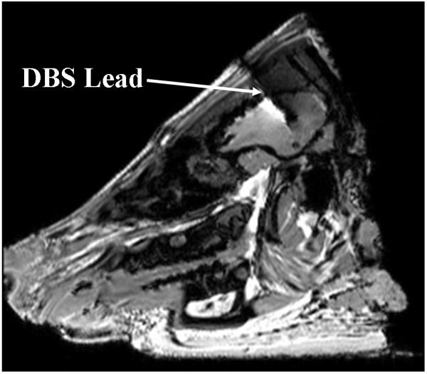
DBS lead in the porcine brain. ~1mm wide DBS lead was imaged as a ~5mm wide DBS lead with a GRE sequence at 3T due to susceptibility artifacts.
Figure 2.
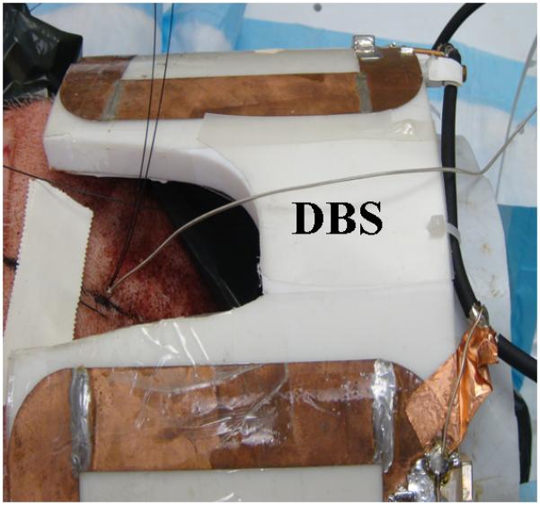
The extra-cranial portion of the DBS lead is placed parallel to the 9.4T, four loop head coil axial direction.
Figure 3.
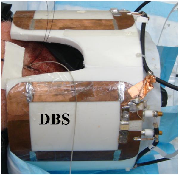
The extra-cranial portion of the DBS lead is placed perpendicular to the 9.4T, four loop head coil axial direction.
Next, the RF coil was tuned and matched to 400.2 MHz. Giga-tronic power meter was attached to the coil. The net CW RF power delivered to the coil was adjusted to produce ~ 3 W/kg whole head average SAR assuming 100% coil coupling efficiency. The actual coupling efficiency of the RF coil to the head was estimated at ~80 %. The actual efficiency was determined by measuring quality factor of the loaded and unloaded coil for two pig heads of weights comparable to the pig heads used in this study. The RF power was delivered to the head and the temperatures were measured after the porcine head thermally equilibrated with the surrounding room air temperature. The thermal equilibrium was determined by monitoring temperatures in the scalp, brain, and room air before the RF power was delivered.
RESULTS
Clinically harmful heating at and near DBS lead electrodes may be induced due to a 15 minute, 400.2 MHz CW RF power deposition with a transmit and receive head coil. Temperature changes in the range of ~0-26.8 °C and ~0-23.5 °C were measured near the second DBS lead electrode (at 10 mm depth in the brain) and at the DBS lead tip (at 15 mm depth in the brain) over baseline room air temperature, respectively (Table 1).
Table 1.
Maximum temperature change (ΔT, °C) in a porcine head due to a DBS lead (#3389, Medtronic Inc., Minneapolis) after a 15 minute, CW, 400.2 MHz RF power deposition with a four loop head coil
| Pig weight (kg) |
Pig head weight (kg) |
Whole head average SAR (W/kg) |
ΔT (°C) due to axial extra -cranial DBS lead placement |
ΔT (°C) due to azimuthal extra-cranial DBS lead placement |
||||||
|---|---|---|---|---|---|---|---|---|---|---|
| Air | Scalp | Brain (10 mm) |
Brain (15 mm) |
Air | Scalp | Brain (10 mm) |
Brain (15 mm) |
|||
| 101.0 | 5.57 | 2.88 | 0.22 | 0.67 | −0.17 | 0.01 | 0.28 | 1.88 | 22.61 | 14.12 |
| 83.4 | 5.44 | 2.91 | 0.40 | 0.73 | 2.53 | 2.27 | 0.19 | 1.64 | 26.81 | 23.46 |
| 84.4 | 5.57 | 3.05 | 0.21 | 0.64 | 2.86 | 2.20 | 0.05 | 1.36 | 16.83 | 11.94 |
| 72.2 | 5.27 | 2.90 | 0.51 | 1.43 | 5.24 | 3.54 | 0.23 | 2.04 | 19.90 | 12.90 |
RF heating was significantly reduced (p at the scalp = 0.007, p at 10 mm = 0.006, p at 15 mm = 0.016; paired, two-sided t test) when the extra-cranial portion of the DBS lead was placed parallel to the coil axial direction compared to the perpendicular to the coil axial direction (Table 3). During the axial placement of the extra-cranial DBS lead, maximum temperature changes in the range of ~0-5.2 °C (average ΔT = 2.62 °C, SD = 2.22 °C) and ~0-3.5 °C (average ΔT = 2.00 °C, SD = 1.47 °C) were measured near the second DBS lead electrode and the DBS lead tip, respectively (Table 1). During the azimuthal placement of the extra-cranial DBS lead, maximum temperature changes in the range of ~16.8-26.8 °C (average ΔT = 21.54 °C, SD = 4.23 °C) and ~11.9-23.5 °C (average ΔT = 15.61 °C, SD = 5.31 °C) were measured near the second DBS lead electrode and the DBS lead tip, respectively (Table 1). Figure 4 presented a typical RF heating response in one of the porcine heads for the axial extra-cranial DBS lead placement. Figure 5 presented a typical RF heating response in the same porcine head for the azimuthal extra-cranial DBS lead placement.
Table 3.
p-value for two sided paired t-test to statistically compare the reduction of heating when the extra-cranial portion of the DBS lead (#3389, Medtronic Inc., Minneapolis) was placed parallel (i.e., axially) instead of perpendicular (i.e., azimuthally) to the 9.4T RF head coil axis. The t-test was performed using the temperature change data presented in Tables 1-2.
| Temperature Change Duration (minute) |
Air | Scalp | Brain (10 mm) |
Brain (15 mm) |
|---|---|---|---|---|
| 15 | 0.138 | 0.007 | 0.006 | 0.016 |
| 1 | 0.286 | 0.066 | 0.004 | 0.017 |
Figure 4.
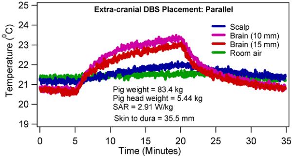
Temperature changes in a porcine head due to 15 minutes of CW, 400.2 MHz RF power with a four loop head coil when the extra-cranial portion of the DBS lead was placed parallel to the coil axial direction.
Figure 5.
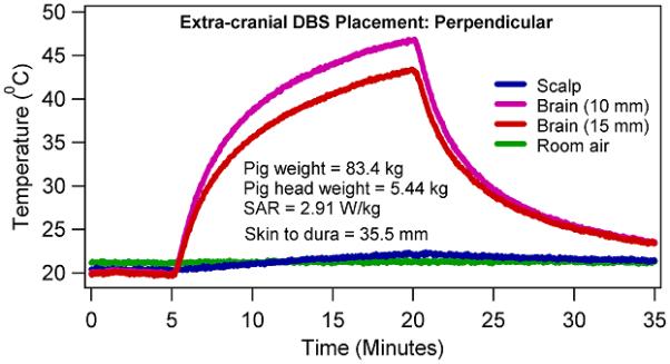
Temperature changes in a porcine head due to 15 minutes of CW, 400.2 MHz RF power with a four loop head coil when the extra-cranial portion of the DBS lead was placed perpendicular to the coil axial direction.
Temperature changes at the scalp were statistically insignificant between the axial and azimuthal placements of the extra-cranial DBS lead after 1 minute of RF heating (p = 0.066, paired, two-sided t test), (Table 3). Thus, coil RF power deposition did not statistically significantly alter between the axial and azimuthal placements of the extra-cranial DBS lead. Temperature changes were statistically significant at the scalp between the axial and azimuthal placements of the extra-cranial DBS lead after 15 minutes of RF heating (p = 0.007; paired, two-sided t test). Scalp temperature change was greater during the azimuthal DBS lead placement than the corresponding temperature change during the axial DBS lead placement. This may be attributed to the diffusion of thermal energy from the brain near the DBS electrodes to the scalp and from the exiting heated lead.
Temperatures continued to rise during the CW RF power deposition. In other words, no thermal steady state was achieved in porcine heads during the 15 minutes of the RF power deposition (e.g., Figures 4-5). Rate of temperature change was higher in the first one minute compared to the last one minute in porcine heads due to the effects of thermal diffusion.
DISCUSSION
Several important and clinically relevant observations were made. First, clinically harmful heating near DBS electrodes may be induced by the orientation of the extra-cranial portion of the DBS lead at ultra-high fields (Table 1, Figures 4-5). The observation was explained since the RF heating was dependent on the currents induced in the DBS coiled wire by the time varying electromagnetic fields. Induced currents in the extra-cranial portion of a DBS lead depended on the placement of the extra-cranial DBS lead with respect to a transmit RF coil. Strong dependence of RF heating near DBS electrodes on the orientation of the extra-cranial DBS lead with respect to a coil suggested that the human head geometry should be investigated to determine human relevant RF heating near DBS electrodes in the human brain. The inherent distribution of appropriate electromagnetic properties in fresh human cadavers at a Larmor frequency will facilitate the development of clinically feasible protocols to minimize RF heating due to a DBS lead during imaging at ultra-high fields. Such protocols should be developed for a given RF coil and DBS lead.
In a previous report, temperature changes other than the noise could not be detected due to a DBS lead (model 3387, Medtronic Inc., Minneapolis) at 1.5T and 2.35T in a NaCl solution-filled phantom with a body coil (15). However, the importance of the placement of the extra-cranial portion of a DBS device (DBS lead, percutaneous connector lead, and impulse pulse generator) relative to an RF coil on RF heating has been demonstrated earlier both at 1.5T and 2.35T (15,16).
The presence of normal cranial perfusion in live porcine models is expected to reduce the maximum temperature change near DBS electrodes. However, the region of brain tissue near DBS electrodes with clinically significant RF heating might be altered due to the redistribution of the RF heating by the blood. This is so because the blood arriving to the tissue near heated electrodes will heat up due to the temperature difference between the tissue and the blood. This heated blood will raise the temperature of the colder tissues as it travels away from the heated electrode. Therefore, the blood flow will decrease the maximum temperature of the heated tissue. However, the temperature of the other tissue regions will be increased or decreased depending on the flow and its temperature, significantly altering the region of tissue with clinically significant RF heating.
Next, regarding safe brain temperature change thresholds, neuronal tissue is considered as one of the most sensitive tissue types to temperature changes (33). However, to date exact cellular temperature thresholds are unknown beyond which cellular and systemic functions of a mammalian brain are adversely and irreversibly compromised. Brain temperature changes greater than 1 degree C may be acceptable near implants. Cumulative Equivalent Minutes ~43 is routinely used to determine irreversible cell injury during thermal therapies (28). Whole body relatively uniform temperature changes of ~2 °C are safely experienced by humans during fever and porcine models (34). However, as mentioned above the International Commission on Non-Ionizing Radiation Protection recommends 1 °C temperature change as the maximum allowable safe temperature change in the head during MRI (22). Indications exist that the thermal threshold is a function of the cellular temperature-time history (27). Further, in vivo temperature changes on the order of 1 °C may adversely affect thermoregulatory physiology (27,35-38). Given the significant role of the blood flow in determining the tissue temperature and the unknown nature of the local and systemic thermo-physiological effects due to the local mammalian brain heating in the range of 37-40 °C both human and animal models are needed to understand RF safety with implanted DBS devices. Perfused, fresh cadaver models are needed to understand the role of blood flow in determining tissue temperatures near DBS devices. Live, thermo-physiologically conservative animal models (e.g., swine) are required to understand local and systemic thermo-physiological effects due to local mammalian brain heating in the range of 37-40 °C (11,27,29).
Second, statistically significant reduction in the RF heating in the brain was observed when the extra-cranial portion of the DBS lead was placed parallel to the axial direction, instead of perpendicular to axial direction (at the scalp = 29.9-64.36 %, at 10 mm in the brain = ~73.67-100.75%, at 15 mm in the brain = ~72.56-99.93%), (Table 1). The observation was explained since the magnetic flux crossing the DBS coiled wires approached zero when the magnetic field direction and coiled wire direction were parallel (i.e., when the extra-cranial DBS lead was oriented in the axial direction) inducing relatively less RF heating. The magnetic flux crossing the DBS coiled wires approached maximum when the magnetic field direction and coiled wire direction were perpendicular (i.e., when the lead was oriented in the azimuthal direction) inducing relatively more RF heating. Induced electromotive force and thus, current in a coiled wire is proportional to the rate of change of total magnetic flux. The observation indicated the feasibility of developing protocols for the placement of the extra-cranial DBS to minimize RF heating at the highest fields for a given RF coil and DBS lead. Note that the RF heating during a typical loop placement of the extra-cranial DBS underneath the scalp was expected to be between the RF heating measured during the axial and azimuthal placements of the extra-cranial DBS. The observation was encouraging since it was observed that the RF heating decreased as the distance between the extra-cranial DBS lead and RF coil surface increased. Expected temperature rise if the extra-cranial portion of the lead is laid out along the longitudinal axis of the coil is expected to be similar to the temperature rise when the extra-cranial lead was placed in the coil axial direction.
Third, strong temporal and spatial temperature gradients may exist near DBS electrodes (Table 1, Figure 5). Strong temporal gradients were apparent from ~16.8-26.8 °C (average temperature rise = 21.54 °C, SD = 4.23 °C) temperature rise in 15 minutes of the RF power deposition at the second DBS electrode when the extra-cranial portion of the lead was placed in the coil azimuthal direction. Strong spatial temperature gradient was apparent from ~3.4-8.5 °C (average temperature difference = 5.93 °C, SD = 2.27 °C) temperature difference between the two, 5 mm apart, fluoroptic temperature probes in the brain after 15 minutes of the RF power deposition for the same extra-cranial lead orientation. Strong temporal and spatial temperature gradients near DBS electrodes suggested that accurate computational modeling of electromagnetic and resultant temperature fields required high temporal and spatial resolution and/or higher order elements. Convergence of a solution must be checked by increasing resolution to have confidence in the simulated electromagnetic and temperature fields. Further, strong spatial gradients suggested the possibility of non-uniform RF heating near DBS electrodes. Note that the fluoroptic probe near the DBS lead tip (15 mm deep in the brain) was only 1.5 mm away from the first DBS electrode.
Fourth, temperatures kept increasing in the brain and scalp during 15 minutes of the RF power deposition and thermal steady state was not achieved. The observation was important since it suggested that imaging time must be reduced to minimize the RF heating. Future investigations in cadavers and animal models using MR thermometry outside the susceptibility artifact range of the device and bioheat thermal modeling may provide useful indications to improve safety during imaging of the patients implanted with DBS devices at high and ultra-high fields (39).
In comparing the present study with previous studies, Rezai et al. measured maximum temperature changes ranging from 2.3 – 7.1 °C in a gel phantom after 15 minutes of MRI with a head coil at 1.5 T. The scanner reported whole body average SAR ranged from 0.07-0.24 W/kg (16). Finelli et al. measured maximum temperature changes ranging from 0.2-6.7 °C in a gel phantom after 15 minutes of MRI with a head coil at 1.5 T. Several pulse sequences were run with the scanner reported whole body average SAR ranging from 0.00-0.24 W/kg (17). These results were comparable to the maximum temperature changes of 0-5.24 °C measured in the present study during the axial placement of the extra-cranial DBS lead (Table 1). Baker et al. measured maximum temperature changes ranging from 0.8-7.3 °C in a gel phantom after 1 minute of a spin echo sequence with a head coil at 3T. Time averaged RF power ranged from 13.2-14.7 W and the scanner reported whole body average SAR ranged from 0.2-0.3 W/kg (19). The temperature changes were lower but comparable to the maximum temperature changes of 0-8.4 °C measured in the current study in the first minute after the RF was started (Table 2). Baker et al. measured maximum temperature changes ranging from 0.7-9.3 °C in a gel phantom after 2 minutes of a spin echo sequence with a head coil at 1.5T. The scanner reported whole head average SAR ranged from 0.6-6.5 W/kg (14). Carmichael et al. measured the maximum temperature change of 1.4 °C (at 1.5 T, RF power deposition time ~3.5 minutes) and 2.2 °C (at 3.0T, RF power deposition time ~2.0 minutes) with the head coil average SAR of 1.45 W/kg and 2.34 W/kg, respectively (20). The results were lower but comparable to the maximum temperature changes of 0-11.62 °C measured in the present study in two minutes after the RF was started. Stronger RF heating near DBS electrodes at 9.4 T compared to previous RF heating results was attributed to the use of porcine phantom, DBS lead placement, 9.4T head coil, and RF frequency. Also, RF heating depends on the manufacturer, software, and construction of the head coil for a given placement of a DBS device. Therefore, a standard guideline is required in manufacturing head coils, exciting tissues, and computing whole head average specific absorption rates (SARs) to improve safety with implanted medical devices.
Table 2.
Temperature change (ΔT, °C) in a porcine head due to a DBS lead (#3389, Medtronic Inc., Minneapolis) in 1 minute after the CW, 400.2 MHz RF power deposition was started with a four loop head coil
| Pig weight (kg) |
Pig head weight (kg) |
Whole head average SAR (W/kg) |
ΔT (°C) due to axial extra -cranial DBS lead placement |
ΔT (°C) due to azimuthal extra-cranial DBS lead placement |
||||||
|---|---|---|---|---|---|---|---|---|---|---|
| Air | Scalp | Brain (10 mm) |
Brain (15 mm) |
Air | Scalp | Brain (10 mm) |
Brain (15 mm) |
|||
| 101.0 | 5.57 | 2.88 | 0.09 | −0.09 | −0.33 | −0.27 | 0.12 | 0.20 | 6.38 | 1.79 |
| 83.4 | 5.44 | 2.91 | 0.26 | −0.01 | 0.4 | 0.38 | 0.04 | 0.01 | 5.36 | 4.71 |
| 84.4 | 5.57 | 3.05 | 0.03 | −0.11 | 0.72 | 0.33 | 0.01 | 0.02 | 4.42 | 2.07 |
| 72.2 | 5.27 | 2.90 | 0.10 | 0.05 | 2.28 | 1.07 | 0.03 | 0.28 | 8.43 | 4.07 |
Use of a tissue sample may be more desirable for studying RF heating near DBS lead electrodes compared to gel phantoms at high fields and ultra-high fields. This is so because RF heating is a function of the electromagnetic and thermal properties of the sample. Electromagnetic properties of a tissue vary with the frequency. A real tissue inherently possesses appropriate electromagnetic and thermal properties (e.g., porcine brain) (25,26). In comparison, a gel needs to be doped such that it may mimic appropriate electromagnetic and thermal properties of a tissue at a frequency – a process which is challenging and at best approximate especially at ultra-high fields. However, precise placement of DBS electrodes and temperature probes is more complex and time consuming in opaque tissues compared to clear/semi-transparent gels.
Regarding the limitations of the study, although the thermal properties of a porcine head and a human head are similar, temperature changes measured herein in porcine heads may not be assumed as representative temperature changes in un-perfused cadaver heads with implanted DBS leads imaged at 9.4 T with a head coil. This is so since the RF heating depends on the head geometry, body geometry, blood perfusion, DBS lead placement with respect to an RF coil, RF coil, and Larmor frequency. Future studies employing fresh perfused cadavers are needed to study RF heating near DBS electrodes in the brain and develop clinically feasible protocols to minimize RF heating during imaging at the highest fields.
In conclusion, clinically harmful temperature changes might result at and near DBS lead electrode-brain contacts due to the orientation of the extra-cranial portion of a DBS lead at ultra-high fields. However, development of the protocols seemed feasible to significantly reduce RF heating by favorably placing the extra-cranial DBS lead with respect to a transmit and receive head coil at the highest fields.
Acknowledgments
Grant Support: CA94318, EB0000895, CA94200, C06 RR12147, C06 RR17557, P41 RR08079, EB006835, EB007327, and the Keck foundation. Dr. Absoch was supported by a Career Development Award from the National Center for Research Resources (5K12-RR03358-03).
Contributor Information
Devashish Shrivastava, Center for Magnetic Resonance Research, University of Minnesota, 2021, 6th St SE, Minneapolis, MN 55455.
Aviva Abosch, Dept of Neurosurgery, University of Minnesota, D-429 Mayo, 420 Delaware Street SE, Minneapolis, MN 55455.
Timothy Hanson, Division of Biostatistics, University of Minnesota, MMC 303 Mayo, 420 Delaware Minneapolis, MN 55455, USA
Jinfeng Tian, Center for Magnetic Resonance Research, University of Minnesota, 2021, 6th St SE, Minneapolis, MN 55455
Akshay Gupte, Dept of Neurosurgery, University of Minnesota, D-425 Mayo, 420 Delaware Street SE, Minneapolis, MN 55455
Paul A. Iaizzo, Department of Surgery, University of Minnesota, MMC 1 Mayo, B195, 420 Delaware, Minneapolis, MN 55455, USA
REFERENCES
- 1.Gruetter R, Weisdorf SA, Rajanayagan V, et al. Resolution improvements in in vivo H-1 NMR spectra with increased magnetic field strength. Journal of Magnetic Resonance. 1998;135(1):260–264. doi: 10.1006/jmre.1998.1542. [DOI] [PubMed] [Google Scholar]
- 2.Zhang Y, Li S, Shen J. Automatic high-order shimming using parallel columns mapping (PACMAP) Magn Reson Med. 2009;62(4):1073–1079. doi: 10.1002/mrm.22077. [DOI] [PMC free article] [PubMed] [Google Scholar]
- 3.Lee J, Lustig M, Kim DH, Pauly JM. Improved shim method based on the minimization of the maximum off-resonance frequency for balanced steady-state free precession (bSSFP) Magn Reson Med. 2009;61(6):1500–1506. doi: 10.1002/mrm.21800. [DOI] [PMC free article] [PubMed] [Google Scholar]
- 4.Vaughan JT, Adriany G, Snyder CJ, et al. Efficient high-frequency body coil for high-field MRI. Magn Reson Med. 2004;52(4):851–859. doi: 10.1002/mrm.20177. [DOI] [PubMed] [Google Scholar]
- 5.Mekle R, Mlynarik V, Gambarota G, Hergt M, Krueger G, Gruetter R. MR spectroscopy of the human brain with enhanced signal intensity at ultrashort echo times on a clinical platform at 3T and 7T. Magn Reson Med. 2009 doi: 10.1002/mrm.21961. [DOI] [PubMed] [Google Scholar]
- 6.Vaughan JT, Garwood M, Collins CM, et al. 7T vs. 4T: RF power, homogeneity, and signal-to-noise comparison in head images. Magn Reson Med. 2001;46(1):24–30. doi: 10.1002/mrm.1156. [DOI] [PubMed] [Google Scholar]
- 7.Keltner JR, Carlson JW, Roos MS, Wong ST, Wong TL, Budinger TF. Electromagnetic fields of surface coil in vivo NMR at high frequencies. Magn Reson Med. 1991;22(2):467–480. doi: 10.1002/mrm.1910220254. [DOI] [PubMed] [Google Scholar]
- 8.Yang QX, Wang JH, Zhang XL, et al. Analysis of wave Behavior in Lossy dielectric samples at high field. Magnetic Resonance in Medicine. 2002;47(5):982–989. doi: 10.1002/mrm.10137. [DOI] [PubMed] [Google Scholar]
- 9.Van de Moortele PF, Akgun C, Adriany G, et al. B(1) destructive interferences and spatial phase patterns at 7 T with a head transceiver array coil. Magn Reson Med. 2005;54(6):1503–1518. doi: 10.1002/mrm.20708. [DOI] [PubMed] [Google Scholar]
- 10.Vaughan T, DelaBarre L, Snyder C, et al. 9.4T human MRI: preliminary results. Magn Reson Med. 2006;56(6):1274–1282. doi: 10.1002/mrm.21073. [DOI] [PMC free article] [PubMed] [Google Scholar]
- 11.Shrivastava D, Hanson T, Schlentz R, et al. Radiofrequency heating at 9.4T: in vivo temperature measurement results in swine. Magn Reson Med. 2008;59(1):73–78. doi: 10.1002/mrm.21425. [DOI] [PMC free article] [PubMed] [Google Scholar]
- 12.Abragam A. Principles of Nuclear Magnetism. Oxford University Press; 1983. [Google Scholar]
- 13.Jackson JD. Classical Electrodynamics. John Wiley & Sons, Inc.; New York: 1999. [Google Scholar]
- 14.Baker KB, Tkach JA, Phillips MD, Rezai AR. Variability in RF-induced heating of a deep brain stimulation implant across MR systems. J Magn Reson Imaging. 2006;24(6):1236–1242. doi: 10.1002/jmri.20769. [DOI] [PubMed] [Google Scholar]
- 15.Georgi JC, Stippich C, Tronnier VM, Heiland S. Active deep brain stimulation during MRI: a feasibility study. Magn Reson Med. 2004;51(2):380–388. doi: 10.1002/mrm.10699. [DOI] [PubMed] [Google Scholar]
- 16.Rezai AR, Finelli D, Nyenhuis JA, et al. Neurostimulation systems for deep brain stimulation: in vitro evaluation of magnetic resonance imaging-related heating at 1.5 tesla. J Magn Reson Imaging. 2002;15(3):241–250. doi: 10.1002/jmri.10069. [DOI] [PubMed] [Google Scholar]
- 17.Finelli DA, Rezai AR, Ruggieri PM, et al. MR imaging-related heating of deep brain stimulation electrodes: in vitro study. AJNR Am J Neuroradiol. 2002;23(10):1795–1802. [PMC free article] [PubMed] [Google Scholar]
- 18.Kainz W, Neubauer G, Uberbacher R, Alesch F, Chan DD. Temperature measurement on neurological pulse generators during MR scans. Biomed Eng Online. 2002;1:2. doi: 10.1186/1475-925X-1-2. [DOI] [PMC free article] [PubMed] [Google Scholar]
- 19.Baker KB, Tkach J, Hall JD, Nyenhuis JA, Shellock FG, Rezai AR. Reduction of magnetic resonance imaging-related heating in deep brain stimulation leads using a lead management device. Neurosurgery. 2005;57(4 Suppl):392–397. doi: 10.1227/01.neu.0000176877.26994.0c. discussion 392-397. [DOI] [PubMed] [Google Scholar]
- 20.Carmichael DW, Pinto S, Limousin-Dowsey P, et al. Functional MRI with active, fully implanted, deep brain stimulation systems: safety and experimental confounds. Neuroimage. 2007;37(2):508–517. doi: 10.1016/j.neuroimage.2007.04.058. [DOI] [PubMed] [Google Scholar]
- 21.Baker KB, Tkach JA, Nyenhuis JA, et al. Evaluation of specific absorption rate as a dosimeter of MRI-related implant heating. J Magn Reson Imaging. 2004;20(2):315–320. doi: 10.1002/jmri.20103. [DOI] [PubMed] [Google Scholar]
- 22.ICNIRP Medical Magnetic Resonance (MR) Procedures: Protection of Patients. Health Physics. 2004;87(2):197–216. doi: 10.1097/00004032-200408000-00008. [DOI] [PubMed] [Google Scholar]
- 23.CDRH-FDA Guidance for Industry and FDA Staff - Criteria for Significant Risk Investigations of Magnetic Resonance Diagnostic Devices. 2003:1–3. [Google Scholar]
- 24.Bhidayasiri R, Bronstein JM, Sinha S, et al. Bilateral neurostimulation systems used for deep brain stimulation: in vitro study of MRI-related heating at 1.5 T and implications for clinical imaging of the brain. Magn Reson Imaging. 2005;23(4):549–555. doi: 10.1016/j.mri.2005.02.007. [DOI] [PubMed] [Google Scholar]
- 25.Gabriel C, Gabriel S, Corthout E. The dielectric properties of biological tissues: I. Literature survey. Phys Med Biol. 1996;41(11):2231–2249. doi: 10.1088/0031-9155/41/11/001. [DOI] [PubMed] [Google Scholar]
- 26.Holmes KR. Thermal Conductivity of Selected Tissues. In: Diller KR, editor. Biotransport - Heat and Mass Transfer in Living Systems. Vol. 858. The New York Academy of Sciences; New York: 1998. pp. 18–19. Annals of the New York Academy of Sciences. [Google Scholar]
- 27.Shrivastava D, Hanson T, Kulesa J, DelaBarre L, Snyder C, Vaughan JT. Radio-Frequency Heating at 9.4T–In Vivo Thermoregulatory Temperature Response in Swine. Magn Reson Med. 2009;62(4):888–895. doi: 10.1002/mrm.22072. [DOI] [PMC free article] [PubMed] [Google Scholar]
- 28.Dewhirst MW, Viglianti BL, Lora-Michiels M, Hanson M, Hoopes PJ. Basic principles of thermal dosimetry and thermal thresholds for tissue damage from hyperthermia. Int J Hyperthermia. 2003;19(3):267–294. doi: 10.1080/0265673031000119006. [DOI] [PubMed] [Google Scholar]
- 29.Mount LE. In: Adaptation to thermal environment - Man and his productive animals. Barrington EJW, Willis AJ, Sleigh MA, editors. University Park Press; Baltimore: 1979. p. 333 p. [Google Scholar]
- 30.Avdievich NI, Hetherington HP, Kuznetsov AM, Pan JW. 7T head volume coils: improvements for rostral brain imaging. J Magn Reson Imaging. 2009;29(2):461–465. doi: 10.1002/jmri.21660. [DOI] [PMC free article] [PubMed] [Google Scholar]
- 31.Scheenen TW, Heerschap A, Klomp DW. Towards 1H-MRSI of the human brain at 7T with slice-selective adiabatic refocusing pulses. Magma. 2008;21(1-2):95–101. doi: 10.1007/s10334-007-0094-y. [DOI] [PMC free article] [PubMed] [Google Scholar]
- 32.Michaeli S, Garwood M, Zhu XH, et al. Proton T2 relaxation study of water, N-acetylaspartate, and creatine in human brain using Hahn and Carr-Purcell spin echoes at 4T and 7T. Magn Reson Med. 2002;47(4):629–633. doi: 10.1002/mrm.10135. [DOI] [PubMed] [Google Scholar]
- 33.Adey WR. Tissue interaction with nonionizing electromagnetic fields. Physiological Reviews. 1981;61(2):435–502. doi: 10.1152/physrev.1981.61.2.435. [DOI] [PubMed] [Google Scholar]
- 34.Guyton AC, Hall JE. Textbook of medical physiology. Elsevier Inc.; Philadelphia: 2006. [Google Scholar]
- 35.Kauppinen K. Sauna, shower, and ice water immersion. Physiological responses to brief exposures to heat, cool, and cold. Part III. Body temperatures. Arctic Med Res. 1989;48(2):75–86. [PubMed] [Google Scholar]
- 36.Mednikova YS, Pasikova NV. The temperature sensitivity of the cholinergic responses of cortical neurons in the guinea pig brain. Neurosci Behav Physiol. 2005;35(6):615–621. doi: 10.1007/s11055-005-0101-6. [DOI] [PubMed] [Google Scholar]
- 37.Guatteo E, Chung KK, Bowala TK, Bernardi G, Mercuri NB, Lipski J. Temperature sensitivity of dopaminergic neurons of the substantia nigra pars compacta: involvement of transient receptor potential channels. J Neurophysiol. 2005;94(5):3069–3080. doi: 10.1152/jn.00066.2005. [DOI] [PubMed] [Google Scholar]
- 38.Hori Y, Nakayama T. Temperature sensitivity of the preoptic and anterior hypothalamic neurons in organ culture. Tohoku J Exp Med. 1982;136(1):79–87. doi: 10.1620/tjem.136.79. [DOI] [PubMed] [Google Scholar]
- 39.Shrivastava D, Vaugahn J. A generic bioheat transfer thermal model for a perfused tissue. ASME Journal of Biomechanical Engineering. 2009;131(7):074506. doi: 10.1115/1.3127260. [DOI] [PMC free article] [PubMed] [Google Scholar]