Abstract
A positive interaction between human bone tissue and synthetics is crucial for the success of bone-regenerative materials. A greater understanding of the mechanisms governing bone-bonding is often gained via visualization of the bone–implant interface. Interfaces to bone have long been imaged with light, X-rays and electrons. Most of these techniques, however, only provide low-resolution or two-dimensional information. With the advances in modern day transmission electron microscopy, including new hardware and increased software computational speeds, the high-resolution visualization and analysis of three-dimensional structures is possible via electron tomography. We report, for the first time, a three-dimensional reconstruction of the interface between human bone and a hydroxyapatite implant using Z-contrast electron tomography. Viewing this structure in three dimensions enabled us to observe the nanometre differences in the orientation of hydroxyapatite crystals precipitated on the implant surface in vivo versus those in the collagen matrix of bone. Insight into the morphology of biointerfaces is considerably enhanced with three-dimensional techniques. In this regard, electron tomography may revolutionize the approach to high-resolution biointerface characterization.
Keywords: hydroxyapatite, bone, transmission electron microscopy, electron tomography
1. Introduction
Calcium phosphate ceramics have vast applications in the biomedical field. Of these calcium phosphates, hydroxyapatite (HA) (Ca10(PO4)6(OH)2) is of particular interest because of its composition being similar to the mineral component of bone. It is well known that HA is a bioactive material, in that it precipitates an apatite layer on its surface in vivo, enabling it to form a chemical bond with bone (Hench 1998). Such bone-bonding capabilities are of particular interest in the bone regeneration field. Improving the design, performance and longevity of bone-regenerative scaffold materials depends strongly on a thorough understanding of this interfacial interaction in vivo.
Techniques for visualizing biointerfaces are not new. However, with advances in technology, a transition from two- to three-dimensional analysis is becoming standard practice. The advent of laboratory micro-computed X-ray tomography equipment has resulted in the routine three-dimensional analysis of biomaterials themselves. Indeed, the ability to visualize and quantify scaffold geometries is crucial for improving their design, although without the use of a synchrotron X-ray source, a resolution of only a few micrometres is attainable (Weiss et al. 2003; Jones et al. 2009). With the exception of recent developments in focused ion beam (FIB) slice and view reconstructions (Giannuzzi et al. 2007), the three-dimensional analysis of biomaterial–bone interfaces by other techniques is quite limited. The drawback of X-ray and dual-beam techniques, such as FIB, is quite simple; their low-resolution limits their use in understanding bone-bonding at the nanometre or ultrastructural level. Shifting to electron tomography marks a new threshold for understanding biointerfaces in three dimensions.
Z-contrast electron tomography is a valuable tool for visualizing three-dimensional structures through the collection of a series of two-dimensional projections. Using scanning transmission electron microscopy (STEM) to collect images over a large angular range presents a number of advantages over conventional TEM-based tomography. The scanning electron beam preserves the quality of the sensitive biological samples over the long acquisition times required, whereas a fixed beam, such as that used in TEM, may introduce larger amounts of beam damage (Williams & Carter 1996; Midgley & Weyland 2003). In addition, the high-angle annular dark-field detector (HAADF) in STEM collects predominantly incoherently scattered electrons. This enables the formation of images sensitive to the atomic number Z of the elements under the electron beam, without contributions from diffraction contrast. Therefore, the simultaneous acquisition of morphological and compositional information is accomplished with HAADF STEM (Midgley & Weyland 2003). As such, STEM tomography is extremely useful for the study of biointerfaces where only slight chemical changes occur, such as at the interface between HA and bone. This study demonstrates the value of Z-contrast tomography with a reconstruction of the HA scaffold and human bone interface.
2. Material and methods
2.1. Implantation, retrieval and processing of scaffolds
HA scaffolds (Ø = 3 mm and l = 4 mm) were implanted in the premolar region of the human maxilla. Twelve patients (six men and six women, 48–72 years old) received the implants in 4 mm deep holes formed by twist drills with 3 mm diameter. The results of one patient are included in this paper. After seven months, implants were removed from the surrounding bone using a trephine drill, fixed in glutaraldehyde and embedded in plastic resin (LR White, The London Resin Co. Ltd., Hampshire, UK). Embedded blocks were divided into two sections longitudinally (Exakt cutting and grinding equipment, Exakt Apparatebau, Norderstedt, Germany). Sections for light microscopy were ground to 15–20 µm and stained with 1 per cent toluidine blue, while sections for scanning electron microscopy (SEM) were polished and sputter-coated with a thin conductive layer of gold. Ethical approval for the human study was obtained from the ethical research committee at Linköping University, Linköping, Sweden (Dnr. M35-04).
2.2. Light and scanning electron microscopy
Preliminary investigations were performed with light and electron microscopy. Light microscopic morphometry was performed using a Nikon Elipse E600 light microscope. Back-scattered electron micrographs were acquired using a JEOL 7000F FEG SEM operated at an acceleration voltage of 15 kV.
2.3. FIB preparation method
Samples for TEM were prepared using an FIB microscope with in situ lift-out method. A NVision 40 dual-beam FIB (Carl Zeiss AG, Germany) equipped with a 30 kV gallium ion column, FEG SEM, carbon gas injector system and Kleindiek probe drive system (Kleindiek Nanotechnik GmbH, Reutlingen, Germany) was used.
Using electron beam deposition, a thin carbon strip (1 µm in thickness) was deposited to protect the region of interest from ion implantation damage. Trapezoidal trenches were milled on either side of the carbon strip to an approximate depth of 10 µm using an ion beam probe current of 30 nA. The tungsten lift-out probe was attached to the sample by carbon deposition, and the sample cut free using an ion beam current of 6.5 nA. The lamellae was transferred to a copper TEM grid inside the FIB chamber and attached with carbon. Successively lower ion beam currents, down to 40 pA, were used to thin the sample to electron transparency.
2.4. Electron tomography instrumentation and acquisition
Electron microscopy was performed on a FEI Titan 80-300 transmission electron microscope (FEI Company, Eindhoven, The Netherlands) equipped with a Schottky field-emission gun and a CEOS hexapole-based aberration corrector for the image forming lens. The microscope is fitted with a Model 3000 in-column HAADF detector (Fischione Instruments, PA, USA) for imaging in STEM. The microscope was operated at an acceleration voltage of 300 kV in HAADF STEM with an inner semi-angle of 40 mrad.
The Advanced Tomography Holder Model 2020 (Fischione Instruments), specially designed for tomographic series collection, was used with the sample interface aligned parallel to the tilt axis. Automated focusing, image shift and acquisition of a single-axis tomographic tilt series were achieved using the Inspect 3D (FEI Company) software. A linear tilt scheme was used with image acquisition increments of 2° up to tilt angles of ±60°, and 1° for further angles up to ±75°. Images were recorded between −74° and +71° on the HAADF detector.
The three-dimensional reconstructions were computed using a simultaneous iterative reconstruction technique with 20 iterations in Inspect3D (FEI Company). Models for three-dimensional visualization were created in Amira Resolve RT FEI edition 4.1.2 (Visage Imaging) by guided segmentation.
3. Results
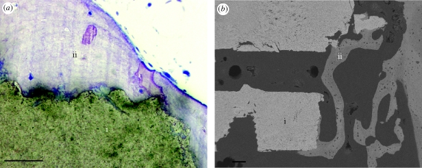
To demonstrate the power of Z-contrast electron tomography, a reconstruction of the interface between a HA scaffold and human bone was carried out. Scaffolds, intended for bone augmentation and regeneration, were evaluated after implantation in the human maxilla for seven months. Preliminary bone–scaffold contact was confirmed using light microscopy. An example of the scaffold interface and intervening bone is shown in figure 1a. Further identification of intimate bone–scaffold contact was determined using back-scattered SEM (figure 1b). An in situ FIB method was used for preparation of electron transparent lamellae for STEM tomography (Grandfield et al. 2010).
Figure 1.
(a) Light microscopic and (b) back-scattered scanning electron micrographs of the scaffold–bone interface. (i) HA scaffold; (ii) bone. Scale bars, (a) 50 µm; (b) 100 µm.
A single-axis tomographic tilt series was collected over the bone–scaffold interface and using back projection, with a simultaneous iterative reconstruction technique, a three-dimensional reconstruction of the section was created. The complete tilt series represents images obtained over an angular range of 146°, and is available in the electronic supplementary material. A selection of these images is shown in figure 2. The tilt series illustrates both the characteristic collagen banding of bone (Hodge & Petruska 1963) with 67 nm periodicity perpendicular to the scaffold surface, and the dense interfacial apatite layer formed in vivo.
Figure 2.
Images from the tomographic tilt series acquired at tilt angles of approximately (a) 0°, (b) −20°, (c) −40° and (d) −60°. (a) (i) The fibrous bone structure; (ii) 80 nm interfacial apatite layer; (iii) HA scaffold; arrow, collagen banding; scale bar, 200 nm.
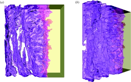
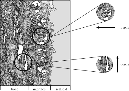
The reconstructed volume represents a section of the tilt series measuring 320 × 260 × 70 nm, and is shown from different angles in figure 3. The complete reconstruction video, showing both volumetric slicing and surface rendering, is available in the electronic supplementary material. The reconstructed three-dimensional volume clearly reveals the distinct orientation of HA crystallites in the fibrous bone structure and at the dense interfacial layer. The HA crystals in the bone are aligned parallel to the scaffold surface, while the HA crystals of the precipitated apatite layer appear to be strongly oriented perpendicular to the scaffold surface. This distinct feature could not be deduced directly from the individual images in figure 2; only with the aid of tomography and the three-dimensional reconstruction is this characteristic visible. A schematic diagram summarizing the orientations of HA crystals in these distinct zones is depicted in figure 4.
Figure 3.
Volumetric reconstructions of the HA scaffold–bone interface from two views—(a,b). The reconstructed volume measures 320 × 260 × 70 nm, with the bone and the interfacial region represented by purple, on the left, while the HA scaffold is yellow, on the right. Notice the clear difference in the orientation of crystals closest to the interface and further into the bone.
Figure 4.
An illustration of the human bone–scaffold interface indicating the differences in HA crystal orientation visible with electron tomography. Crystals in the bone are oriented with their long axis (c-axis) parallel to the scaffold surface, while crystals in the interfacial apatite layer have their c-axis oriented perpendicular to the scaffold surface.
4. Discussion
Information regarding the morphology and arrangement of HA crystallites at the interface between HA and bone was extracted from both the tilt series and tomographic reconstruction. In bone, the HA crystals are arranged such that their long axis is parallel to collagen fibres. Tomograms from calcified tendons have contributed to understanding this arrangement of collagen and HA mineral (Landis et al. 1993). In this instance, this corresponds to the c-axis of HA aligned parallel to the scaffold surface. This result, demonstrated clearly in the tomogram, is consistent with the direction of the collagen banding as noted in the tilt series. The collagen banding, shown perpendicular to the scaffold in the tilt series, confirms the arrangement of collagen, and subsequently the HA in bone, parallel to the scaffold surface.
The formation of an interfacial apatite layer on HA is known to be governed by a dissolution re-precipitation mechanism, resulting in carbonated HA growth. However, there are controversial opinions on the arrangement of apatite particles during formation. Analytical techniques such as electron and X-ray diffraction, as well as imaging with high-resolution TEM have suggested both preferred and non-preferred orientation of crystallites on the HA surface (Jarcho 1981; Daculsi et al. 1989, 1990; Fujita et al. 2003). Previous TEM investigations have exhibited crystal growth perpendicular to the surface of the original material (Daculsi et al. 1990). Other observations involving atomic resolution imaging have even suggested the possibility of epitaxial growth of apatite on HA (Fujita et al. 2003). It certainly appears from our reconstructions that a preferential orientation exists perpendicular to the scaffold surface. Electron tomography has shown that HA crystallites, which compose the interfacial apatite layer, are oriented with their c-axis perpendicular to the scaffold surface. The origin of the orientation differences between HA crystallites present in bone and those formed in the interfacial apatite layer is not well understood. It can be speculated that the disparity in orientation results from differences in cellular versus solution-mediated HA formation (Ducheyne & Qiu 1999).
5. Conclusions
The ability to visualize biointerfaces in three dimensions has vast implications in the field of life sciences. Shifting from two- to three-dimensional imaging drastically increases the structural and morphological information attainable from interfaces. In this work, the tomogram from a HA–bone interface was presented. Z-contrast electron tomography enabled an enhanced understanding of the arrangement of HA crystallites in bone and at the bone–implant interface. The feasibility of using STEM tomography for the three-dimensional structural analysis of bone–implant interfaces at the nanometre scale has been successfully demonstrated. Indeed, electron tomography as a characterization technique can easily be extended to the study of other biointerfaces involving ceramics, metals, polymers and natural materials.
Acknowledgements
This work was supported by the Natural Sciences and Engineering Research Council of Canada (NSERC), the Institute for Biomaterials and Cell Therapy (IBCT) in Gothenburg, Sweden and the Canadian Center for Electron Microscopy, a facility supported by NSERC and McMaster University.
References
- Daculsi G., Legeros R., Mitre D. 1989. Crystal dissolution of biological and ceramic apatites. Calcif. Tissue Int. 45, 95–103. ( 10.1007/BF02561408) [DOI] [PubMed] [Google Scholar]
- Daculsi G., Legeros R., Heughebaert M., Barbieux I. 1990. Formation of carbonate-apatite crystals after implantation of calcium phosphate ceramics. Calcif. Tissue Int. 46, 20–27. ( 10.1007/BF02555820) [DOI] [PubMed] [Google Scholar]
- Ducheyne P., Qiu Q. 1999. Bioactive ceramics: the effect of surface reactivity on bone formation and bone cell function. Biomaterials 20, 2287–2303. ( 10.1016/S0142-9612(99)00818-7) [DOI] [PubMed] [Google Scholar]
- Fujita R., Yokoyama A., Nodasaka Y., Kohgo T., Kawasaki T. 2003. Ultrastructure of ceramic-bone interface using hydroxyapatite and beta-tricalcium phosphate ceramics and replacement mechanism of beta-tricalcium phosphate in bone. Tissue Cell 35, 427–440. ( 10.1016/S0040-8166(03)00067-3) [DOI] [PubMed] [Google Scholar]
- Giannuzzi L. A., Phifer D., Giannuzzi N. J., Capuano M. J. 2007. Two-dimensional and 3-dimensional analysis of bone/dental implant interfaces with the use of focused ion beam and electron microscopy. J. Oral Maxillofac. Surg. 65, 737–747. ( 10.1016/j.joms.2006.10.025) [DOI] [PubMed] [Google Scholar]
- Grandfield K., et al. 2010. Bone response to free-form fabricated hydroxyapatite and zirconia scaffolds: a transmission electron microscopy study in the human maxilla. Clin. Implant Dentist. Relat. Res. ( 10.1111/j.1708-8208.2009.00270.x) [DOI] [PubMed] [Google Scholar]
- Hench L. L. 1998. Biomaterials: a forecast for the future. Biomaterials 19, 1419–1423. ( 10.1016/S0142-9612(98)00133-1) [DOI] [PubMed] [Google Scholar]
- Hodge A. J., Petruska J. A. 1963. Aspects of protein structure (ed. Ramachandran G. N.). New York, NY: Academic Press. [Google Scholar]
- Jarcho M. P. D. 1981. Calcium phosphate ceramics as hard tissue prosthetics. Clin. Orthop. Relat. Res. 157, 259–278. [PubMed] [Google Scholar]
- Jones J., Atwood R., Poologasundarampillai G., Yue S., Lee P. 2009. Quantifying the 3D macrostructure of tissue scaffolds. J. Mater. Sci. Mater. Med. 20, 463–471. ( 10.1007/s10856-008-3597-9) [DOI] [PubMed] [Google Scholar]
- Landis W. J., Song M. J., Leith A., McEwen L., McEwen B. F. 1993. Mineral and organic matrix interaction in normally calcifying tendon visualized in three dimensions by high-voltage electron microscopic tomography and graphic image reconstruction. J. Struct. Biol. 110, 39–54. ( 10.1006/jsbi.1993.1003) [DOI] [PubMed] [Google Scholar]
- Midgley P. A., Weyland M. 2003. 3D electron microscopy in the physical sciences: the development of Z-contrast and EFTEM tomography. Ultramicroscopy 96, 413–431. ( 10.1016/S0304-3991(03)00105-0) [DOI] [PubMed] [Google Scholar]
- Weiss P., et al. 2003. Synchrotron X-ray microtomography (on a micron scale) provides three-dimensional imaging representation of bone ingrowth in calcium phosphate biomaterials. Biomaterials 24, 4591–4601. ( 10.1016/S0142-9612(03)00335-1) [DOI] [PubMed] [Google Scholar]
- Williams D. B., Carter C. B. 1996. Transmission electron microscopy: a textbook for materials science. New York, NY: Plenum Press. [Google Scholar]


