

Abstract
Voltage-activated proton (HV) channels are essential components in the innate immune response. HV channels are dimeric proteins with one proton permeation pathway per subunit. It is not known how HV channels are activated by voltage and whether there is any cooperativity between subunits during voltage activation. Using cysteine accessibility measurements and voltage clamp fluorometry, we show data that are consistent with that the fourth transmembrane segment S4 functions as the voltage sensor in HV channels from Ciona intestinalis. Surprisingly, in a dimeric HV channel, S4 in both subunits have to move to activate the two proton permeation pathways. In contrast, if HV subunits are prevented from dimerizing, then the movement of a single S4 is sufficient to activate the proton permeation pathway in a subunit. These results suggest a strong cooperativity between subunits in dimeric HV channels.
Voltage-gated proton (HV) channels have been found in many mammalian cell types, including blood cells, skeletal muscle, lung epithelia, and microglia 1, 2. HV channels have been shown to play a crucial role in the immune system: HV channels in phagocytes are essential for the generation of reactive oxygen species during the respiratory burst, which is critical to the process of phagocytosis and the destruction of foreign pathogens 1, 2.
The sequence encoding HV channels were recently identified in human, mouse and the sea squirt Ciona intestinalis. The gene product was named Hv1 (voltage-activated proton channel 1) or VSOP (Voltage Sensing Only Protein). We here studied the HV channel from Ciona intestinalis, Ci-VSOP, because it expresses much better than the mammalian homologues in Xenopus oocytes. For simplicity, we refer to this channel as Ci-HV channel, or simply HV channel. The high sequence homology and similar functional properties of HV channels from different species suggest that all these channels function similarly and that conclusion drawn from experiments on Ci-HV will be applicable to the mammalian HV channels.
The amino acid sequence of HV channels is homologous to that of voltage-activated potassium (Kv) channels 3, 4. Kv channels have four subunits, each with six transmembrane (TM) segments 5. The first four TM segments of each subunit form a separate voltage-sensing domain, while the last two TM segments from all four subunits form one common pore-forming domain 6-8. HV channels have only two subunits, each with four TM segments 9-11. The four TM segments in HV channels are homologous to the four TM segments in the voltage-sensing domains of Kv channels. Deleting the cytosolic domains of HV channels inhibits the formation of HV dimers, but still generates voltage-activated proton currents 9, 10. This shows that even though HV channels are dimers, each HV subunit contains its own proton permeation pathway and can function as a separate voltage-activated proton channel 9, 10. Here we test whether there is cooperativity between subunits during voltage-activation of HV channels.
In voltage-activated Shaker Kv channels, the fourth TM, S4, which contains several positively-charged residues (Fig. 1a), has been shown to function as the voltage sensor 12-16. Shaker Kv channels are activated by the equivalent movement of 12-14 charges across the membrane electrical field per channel (3-3.5 charges per subunit) 12, 15, 17-19. The majority of these gating charges have been shown to be due to the transmembrane movement of S4 charges 12, 13, 15, 20. Most studies suggest that the main charge movement of the four S4s occurs independently of each other, but that the common pore of a Kv channel opens in a concerted conformational change after the main charge movement has occurred in all four S4s 21-24 (although see 25, 26 for alternative models). The requirement for activation of all four S4s before the channel opens explains the high voltage sensitivity for each Kv channel (12-14 charges/channel).
Figure 1.

State-dependent modification of S4 residues by external MTSET. (a) Alignment of S4 region (dashed box) for Ci-HV, mouse Hv1 (mHV), Shaker K, and the first domain from Nav1.2 channels. (*) mark residues mutated to cysteine and tested with MTS reagents. Arrows marks residue S242 in Ci-HV used for fluorescence experiments. (b-d) Currents from oocyte expressing I248C channels in response to voltage steps from −60 mV to +60 mV (in 20 mV increments, pHo = 7.5), (b) before MTSET, (c) after a 40-seconds application of 100 μM MTSET at −60 mV (and washed for 20 seconds), and (d) after a 20-seconds application of 100 μM MTSET at +60 mV (and washed for 20 seconds). Vholding= −60 mV. (e) Currents in response to a +60-mV voltage step before and after each 10-second MTSET application on closed I248C channels. Closed-state modification was tested by applying 100 μM MTSET at −60 mV for 10 sec, followed by wash-out for 20 seconds. MTSET application was repeated 4 times. (f) Currents in response to a +60-mV voltage step during open-state MTSET application. Open-state modification was tested by applying 100 μM MTSET continuously while stepping to +60 mV for 2 seconds every 10 seconds. MTSET significantly increased the rate of activation. (g) The rate of MTSET modification at −60 mV (□) or +60 mV (□) was measured using the current amplitude at 300 ms after the start of the +60 mV voltage step (red dashed line in e and f). The current amplitude was plotted versus the cumulative MTSET exposure and fitted with an exponential. The fitted second-order rate constant is shown. kopen = 5620 ± 1843 M−1s−1 (n = 4).
In HV channels, S4 has only three positively-charged residues (Fig. 1a). It has been assumed that S4 is also the voltage sensor in HV channels, although this has not been directly shown3, 4. Gating current recordings have not yet been reported for HV channels. Each HV subunit contains its own proton permeation pathway and can function as an independent monomeric voltage-gated proton channel, if prevented from dimerizing 9, 10. Limiting slope measurements have shown that the voltage dependence of HV channels is consistent with the movement of an effective gating charge of at least 6 e0 27. It is not clear whether this relatively high voltage dependence (6 charges/channel) is due to cooperative gating of HV subunits or whether other charges outside of S4 also contribute to the voltage gating of HV channels.
Using cysteine accessibility13 and voltage clamp fluorometry14, we show here data that are consistent with that the S4 moves and functions as a voltage sensor in the HV channels. We also show that the voltage sensitivity is only half in monomeric channels (~3 charges/channel) compared to that in dimeric wild-type (wt) HV channels (~6 charges/channel). We propose a model where in dimeric HV channels both S4s need to be activated before the channel opens, whereas in monomeric HV channels the movement of one S4 can open the channel.
Results
S4 external accessibility consistent with S4 as voltage sensor
If S4 is the voltage sensor in Hv channels, then some of its charges must move relative to the electric field across the membrane during activation. To test this hypothesis, we measured the solvent accessibility of introduced cysteines in and around S4 of Ci-HV channels, to look for state dependent changes in the accessibility of S4 residues (Fig. 1a). We expressed the mutated channels in Xenopus oocytes and assayed the accessibility of the cysteines in both open and closed channels by applying the membrane-impermeable thiol-specific MTS reagents MTSET ([2- (trimethylammonium)ethyl] methanethiosulfonate) and MTSES ( (2-sulfonatoethyl) methanethiosulfonate)13. The modification rate of cysteines was measured by plotting the amplitude of the MTS-induced change as a function of the cumulative exposure to MTS-reagents applied at either hyperpolarized (mainly closed channels) or depolarized (mainly open channels) potentials. Changes in the modification rate of the cysteines between the open and closed states of Hv channels were used to assess whether some residues in S4 move across the membrane between the open and closed states of the channels13.
Perfusion of external and internal MTSET at both depolarized and hyperpolarized potentials had no significant effects on wild-type Hv channels (Supplementary Figs. 1-4). In contrast, external MTSET clearly modified HV channels with a cysteine introduced at position I248 in the open state (Fig. 1b-d). The MTSET modification changed the kinetics of activation (Fig. 1d), shifted the voltage dependence of activation (Supplementary Fig. 2), and slightly decreased the current amplitude of I248C channels (Fig. 1d). It was clear that the reactivity of I248C was state dependent (Fig. 1b-d). I248C channels were not modified by MTSET at hyperpolarized potentials (Fig. 1c), while I248C channels were modified by MTSET at depolarized potentials (Fig. 1d). The MTSET modified I248C channels were still proton selective and blocked by extracellular Zn2+ (Supplementary Fig. 2). External MTSET modified I248C much faster at depolarized potentials than at hyperpolarized potentials (Fig. 1e-g), suggesting that I248C becomes inaccessible at hyperpolarized potentials. A similar state-dependence was found for external MTSET modification of V252C and for external MTSES modification of A246C (Supplementary Fig. 3). We used MTSES to assay the state-dependent access of A246C, because MTSES modification resulted in more robust changes in the currents than MTSET modification. The state-dependent modification of A246C, I248C, and V252C shows that these three residues are protected from MTS modification at hyperpolarized potentials.
Residues further towards the C-terminal, such as L256C, V259C, and N264C, did not display any modification of the currents with extensive external MTSET or MTSES application (Supplementary Fig. 1). In addition, these residues do not label with a fluorescent probe, such as Alexa488-maleimide, whereas residues S242C, L244C, I248C clearly label by fluorescent probes (not shown).
S4 internal accessibility consistent with S4 as voltage sensor
Internal MTSET abolished the proton currents through N264C (Fig. 2a-b) and I262C channels (Supplementary Fig. 4). Internal MTSET modified I262C and N264C much faster at hyperpolarized potentials than at depolarized potentials (Fig. 2c-e and Supplementary Fig. 5), suggesting that these residues become inaccessible in open channels (Fig. 2f). There are two possible explanations for the lack of currents in MTSET modified channels (Fig. 2b and Supplementary Fig. 4). One possibility is that once MTSET has bound to I262C or N264C, then S4 cannot move to its activating state and open the channel (i.e. locked-closed). Another possibility is that the charged MTSET blocks the actual flow of protons in open HV channels. Residues located further towards the N-terminal, such as L256C and V259C, did not display any modification of the currents with extensive internal MTSET application (Supplementary Fig. 4).
Figure 2.

State-dependent modification of S4 residues by internal MTSET. (a-b) Currents from an excised patch containing N264C channels in response to voltage steps from −60 mV to +60 mV (in 20 mV increments), (a) before and (b) after 1mM MTSET was applied. pHi = 5.5 and pHo =7. (b) Currents in response to a +100-mV voltage step every 10 seconds during MTSET application on open N264C channels. Open-state modification was tested by applying 1 mM MTSET at +100 mV for 1 sec, followed by wash-out at +100 mV. Wash-in and wash-out was monitored by the fast changes in current amplitude induced by changes in internal pH: pHi = 5.5 in rinse and pHi = 7.0 in MTSET solution. pHo = 7.0. (c) Currents in response to a +100-mV voltage step every 10 seconds during MTSET application on closed N264C channels. Closed-state modification was tested by applying 1 mM MTSET at −60 mV for 1 sec, followed by wash-out. (e) The rate of MTSET modification was measured using the current amplitude at the end of the +100 mV voltage step (red dashed line in c and d). The current amplitude was plotted versus the cumulative MTSET exposure at +100 mV and at −60 mV), and fitted with an exponential. The fitted second-order rate constant is shown. kopen = 290 ± 32 M−1s−1 (n = 4). (f) Cysteine accessibility data (Supplementary Figs. 1-5) mapped onto the voltage-sensing domains from the crystal structure of the Kv1.2-2.1 chimera channel and the closed-state model of Shaker K channels. Charged S4 residues (ball and stick), S4 residues more accessible to internal MTSET at negative potentials (yellow) and to external MTSET at positive potentials (purple), S4 residues not modified by either internal or external MTSET (green). Solid lines indicate proposed lipid bilayer boundaries and dashed line indicate proposed MTSET accessibility due to water-filled crevices.
The state-dependent accessibility of 5 cysteines (A246C, I248C, V252C, I262C, and N264C) introduced in S4 of HV channels is similar to the state-dependent accessibility of cysteines introduced in S4 of other voltage-gated ion channels13, 28, 29. In these other channels, the N-terminal half of S4 has been suggested to be buried in the membrane or protein at hyperpolarized potentials and to become accessible to the extracellular solution upon depolarization13, 28, 29, whereas the C-terminal half of S4 has been suggested to be in the intracellular solution at hyperpolarized potentials and to become buried in the membrane or protein upon depolarization13, 28, 29. Our accessibility results are consistent with recent models of the S4 movement in Kv channels based on the crystal structure of the Kv1.2-2.1 chimera channel and crosslinking and cysteine accessibility results in Kv channels (Fig. 2f)8, 30, 31. The findings from the cysteine accessibility for these five residues in HV channels are consistent with the possibility that S4 moves and functions as the voltage sensor in HV channels (Fig. 2f).
The accessibility data is consistent with an outward movement of S4 charges during channel opening. Assuming that the S4 movement and the structure of an HV subunit are similar to those in voltage-sensing domains of Kv channels (as in Fig. 2f) and that the electrical field falls linearly across the inaccessible portion of the HV subunit, the cysteine accessibility data suggest that S4 moves the equivalent of 2-3 gating charges in an HV subunit (see Supplementary Fig. 6 for calculation of number of gating charges). The charge movement of S4 could occur in many possible ways; 1) as a movement of a rigid S4 helix (as depicted in Fig. 2f), 2) as changes in aqueous crevices around S4, or 3) as a change in secondary structure of S413, 32.
S4 kinetics consistent with S4 as voltage sensor in HV
To further test whether S4 moves and functions as the voltage sensor in HV channels, we used voltage clamp fluorometry (VCF)14, 33, 34. S242C HV channels were expressed in oocytes and labelled with Alexa488-maleimide fluorophores. In VCF, changes in fluorescence from the fluorophore are assumed to report on conformational changes of the protein region in which the fluorophore is introduced.
For a comparison of the kinetics of the fluorescence signals and the proton currents, we applied high proton buffers (100 mM HEPES) on both sides of the membrane to prevent proton accumulation or depletion in intact oocytes. We injected 50 nl of 1 M HEPES (pH = 7.0) in each oocyte and allowed approximate 30 minutes for the HEPES to equilibrate inside the oocyte to an estimated 100 mM concentration. We measured the reversal potential of the proton currents after each voltage step to check that the proton concentrations were not altered by the proton currents (Fig. 3a). For proton currents up to 10 μA, we did not see any significant changes in the proton current reversal potential, showing that the proton buffers are adequate to prevent proton accumulation or depletion (Fig. 3a-b).
Figure 3.

Kinetics of S4 movement. (a) Currents from an oocyte containing S242C HV channels in response to a voltage protocol (top) with symmetrical 100 mM HEPES in both intra- and extracellular solutions (see Methods). Inset: currents during voltage ramps to measure reversal potentials. pHi = 7 and pHo =7.4. (b) I/V curves during voltage ramps from a. Currents reversed at −21.8 mV, close to the expected proton equilibrium potential EH = −23 mV. Leak and capacitive currents were subtracted off-line using the currents from the ramp following the −60 mV episode. (c) Current (black) and fluorescence (red) from Alexa488-labeled Ci-HV S242C channels for voltage steps between (−80) mV to +100 mV, Vh= −60 mV. (d) Normalized current (black) and fluorescence (red) from c for steps to +40 mV, +60 mV, and +80 mV. Current and fluorescence traces were normalized to their steady-state amplitudes, or fitted steady-state amplitudes (see Methods). Shown in green are the fluorescence signals raised to the power of 2.
As expected if S4 were a voltage sensor14, we measured voltage-dependent changes in fluorescence from fluorophores attached to S4 in HV channels (Fig. 3c). The fluorescence changes had a similar, but not identical, voltage dependence and time course as the ionic currents3, 4 (Fig. 3c-d). The fluorescence changes (Fig. 3d, red) preceded the proton current during depolarizations, and there was a clear delay in the currents (Fig. 3d, black). The fluorescence changes most likely report on the voltage-dependent movement of the positively-charged S4 in HV, similar to what has been reported in other voltage-dependent channels that contain a positively-charged S4 voltage sensor14, 33, 35. That the S4 movement precede the currents is consistent with the hypothesis that S4 is the voltage sensor in HV channels.
As shown above, in S242C HV channels the time course of the fluorescence clearly precedes the time course of the proton currents, which have a prominent delay and a sigmoidal time course (Fig. 3c-d). The fluorescence raised to a power-of-two (Fig. 3d green line) overlaps fairly well on the proton currents (Fig. 3d black line), as if in the dimeric HV channels both S4s need to move before the proton currents can flow. Another possible explanation is that the two subunits are activated independently, but that there are two sequential voltage-dependent opening steps (with similar kinetics and voltage dependence) in each of the subunits in a dimeric channel and that the fluorescence only reports on the first of these two conformational changes. If this were the case, then in monomeric HV channels the kinetic relationship between fluorescence and proton current would be the same as in dimeric HV channels. If, on the other hand, both S4s need to move to activate the proton permeation pathways in dimeric channels, then the kinetic relationship between fluorescence and proton current would be different in monomeric and dimeric HV channels.
S4 movement and proton current in monomeric HV channels
Using VCF, we directly measure the kinetic relationship of S4 movement and current onset in monomeric S242C HV channels. Using Fluorescence Resonance Energy Transfer (FRET; see Methods), we have earlier shown that S242C HV channels are expressed as dimers in the plasma membrane9. Using co-immunoprecipitation, we also showed that the dimerization of the HV subunit is impaired when the N and C terminus are deleted (ΔNΔC) in HV channels9. We here show using FRET that ΔNΔC S242C HV channels are expressed as monomers in the plasma membrane. To show that the truncation of the cytosolic domains (ΔNΔC) abolishes dimerization of the HV subunits, we introduced the S242C mutation in ΔNΔC HV channels and measured the FRET efficiency for these channels. In contrast to the full-length S242C channels (Fig. 4a), the ΔNΔC S242C HV channels did not undergo FRET (Fig. 4b). The FRET efficiency was 0.017 ± 0.004 (n = 5) for ΔNΔC S242C compared to 0.65 ± 0.07 (n = 12) for S242C9. The lack of FRET between ΔNΔC S242C subunits shows that the ΔNΔC 242C HV subunits are expressed as monomeric channels in the plasma membrane.
Figure 4.

Kinetics in monomeric ΔNΔC Ci-HV channels. (a-b) Fluorescence spectra from (a) S242C Ci-HV channels and (b) ΔNΔC S242C Ci-HV channels labelled with Alexa488- maleimide (black) or Alexa488-maleimide and tetramethylrhodamine-carboxylamino-ethyl-methanethiosulfonate (TMR-MTS; red). Note that the donor (Alexa488) fluorescence at 510 nm does not change in ΔNΔC S242C with the addition of the acceptor (TMR), in contrast to the donor fluorescence from S242C. The absence of FRET in b shows that ΔNΔC S242C Ci-HV channels are monomeric channels. (c) Normalized current (black) and fluorescence (red) from Alexa488-labeled ΔNΔC S242C Ci-HV channels for voltage steps as indicated, Vh= −60 mV. 100 mM HEPES in both intra- and extracellular solutions. pHi = 7 and pHo =7.4. Fluorescence traces raised to a power of 2 (green). Inset: Initial part of the traces shown at extended time scale. Scale bar = 50 ms. The small difference between the fluorescence and current traces might be due to a second fast conformational step in the activation of the proton permeation pathway (See Supplementary Fig. 7b & d).
Knowing that S242C are expressed as dimeric HV channels9 and ΔNΔC S242C are expressed as monomeric HV channels (Fig. 4b), we now test our hypothesis that two S4s need to activate in dimeric HV channels to open the proton pathways. As reported above (Fig. 3), in dimeric S242C HV channels, the time course of the fluorescence change clearly precedes the time course of the proton currents, which have a prominent delay and a sigmoidal time course (Fig. 3d). In contrast, in the monomeric ΔNΔC S242C channels, the fluorescence and proton currents essentially overlap, with little delay or sigmoidicity in the proton currents (Fig. 4c). Hence, in the monomeric HV channels, the current and the fluorescence overlap very well, as if only one S4 needs to move before the proton currents can flow. In contrast, in dimeric S242C channels, the fluorescence raised to a power-of-two superimposes on the proton currents (Fig. 3d), as if in the dimeric HV channels both S4s need to move before any proton current can flow.
The effective gating charge is half in monomeric Hv channel
To further test our hypothesis that both S4s need to move to activate the proton currents in dimeric HV channels, we measured the effective gating charge (the gating charge needed to activate the proton current) in dimeric and monomeric HV channels. If our hypothesis is correct, then the effective gating charge would be twice as large in dimeric channels as in monomeric HV channels. If, on the other hand, the two proton permeation pathways in dimeric HV channels are activated independently of each other, then we would expect that the effective gating charge would be the same in dimeric and monomeric HV channels.
The movement of the three charged residues in S4 in an HV subunit could maximally generate an effective gating charge of 3 e0. The S4 movement according to Figure 2 would generate an effective gating charge closer to 2 e0 in a single subunit (Fig. 2f and Supplementary Fig. 6). We therefore would expect that monomeric HV channels would have an effective gating charge of 2-3 e0, whereas dimeric HV channels would have an effective gating charge of 4-6 e0. We here use two techniques to estimate the effective gating charge in HV channels: 1) by fitting the G(V) for HV channel to a Boltzmann curve, G(V) = Gmax/ (1+exp(−zδ(V−V1/2)/kT), we obtain a lower estimate of the effective gating charge (zδ), and 2) by measuring the limiting slope at very low open probabilities using slow voltage ramps (1 mV/s), we obtain a more accurate estimate of the effective gating charge15, 19, 36, 37.
Because the voltage dependence of HV channels is sensitive to pH1, 38, we ensure that the proton concentrations are not altered by the proton currents during the measurements of the G(V)s of HV channels, by measuring the G(V)s in excised macropatches. In addition, HV channels were expressed at low levels to keep proton flows small and high concentrations of pH buffers on both sides of the cell membrane were used to prevent proton accumulation and depletion caused by proton flow through HV channels1, 38.
A triple pulse protocol monitors both channel rundown (possible after channel excision) and proton accumulation (Fig. 5a): 1) a prepulse to +100 mV (Fig. 5a, arrow 1) monitors maximum channel currents during the protocol to control for channel run-down, 2) a second depolarizing voltage pulse to voltages from −60 mV to +80 mV, followed by a voltage step to 0 mV (Fig. 5a, arrow 2) measures the tail currents for the G(V) measurements, and 3) a fast ramp 2 mV/ms (Fig. 5a, arrow 3) measures the reversal potential after each episode of the voltage protocol. The length of the second depolarizing step varies to prevent large proton currents for extended times, which could cause proton accumulation/depletion. In Fig. 5a, we show an example of the currents from this protocol. In this example, there is neither channel rundown, as the amplitude of the prepulse currents are identical for each episode (Fig. 5a, arrow 1), nor any proton accumulation, as there is no change in the proton reversal potential after the different episodes (Fig. 5a inset, arrow 3, and Fig. 5b).
Figure 5.

Estimates of the effective gating charge in wt HV channels. (a) Currents from an excised patch containing wt HV channels in response to a triple pulse protocol (top). Only a subset of voltage steps is shown for clarity. Inset: currents during voltage ramps to measure reversal potentials. pHi = 6 and pHo =7. (b) I/V curves during voltage ramps from a. Currents reversed at −54 mV, close to the expected proton equilibrium potential EH = −57 mV. Leak and capacitive currents were subtracted off-line using the currents from the ramp following the −80 mV step. (c) Corrected G(V), measured at Vtail = 0 mV (arrow 2 in a). Fit with G(V)/Gmax = 1/(1+exp(−zδ(V−V1/2)/kT); V1/2 = 2 mV and zδ = 4.55 e0. (d) Normalized conductance measured from slow ramps between −60 and 0 mV for wt HV channels in pHi = 5.5 and pHo = 7. The lower pHi during the ramps relative to the G(V) measurements increases the currents to better resolve the conductance at negative potentials, but also shifts the V1/2 by approximately −20 mV. Fit with G(V)/Gmax= exp(zδ(V−V1/2)/kT), where zδ = 6.1 e0. (e) Fit of the slope factor zδ for different voltages (from d). (f) Normalized conductance measured from slow ramps between −20 and +80 mV for ΔNΔC HV channels. zδ = 2.2 e0. (g) Fit of the slope factor zδ for different voltages (from f).
Small changes in rundown and reversal potential were corrected for off-line in the construction of the G(V) curves1. For some voltages, the currents rise too slowly to reach steady-state during the second voltage step. Therefore, we fit the currents from the second voltage step to a single exponential (excluding the initial delay of the current time course)1. We correct the tail currents by a correction factor to the fitted steady-state values1. The corrected G(V)s were fitted by a Boltzmann curve, G(V) = Gmax/ (1+exp(−zδ(V-V1/2)/kT) (Fig. 5c). The slope factor for wt dimeric HV channels was zδ = 4.4 ± 0.4 e0 (n = 5), which is a lower limit estimate of the effective gating charge.
Compared to fitting G(V)s with Boltzmann curves, the limiting slope technique can give a more accurate estimate of the effective gating charge that is coupled to channel opening36, 37, 39. Consequently, we also measured the limiting slope at the foot of the conductance versus voltage, G(V), curves for wt dimeric HV channels at very low open probabilities15, 19, 36, 37. The G(V) curves were calculated from currents in excised patches in response to very slow voltage ramps (1 mV/s), to ensure that the channels were in gating equilibrium for all voltages measured15, 37. The slope at negative voltages in a semi-logarithmic plot gave an effective gating charge of zδ = 5.9 ± 0.4 e0 (n = 5) for wt dimeric HV channels (Fig. 5d). We also plot the zδ value estimated at different voltages (Fig. 5e). The estimates of zδ approach a constant value at negative voltages, suggesting that we are approaching the true value for zδ at these voltages. Our zδ value for wt dimeric HV channels is similar to the zδ values found for native HV channels in phagocytes1, 27. In contrast, the zδ values for monomeric ΔNΔC HV channels were 1.6 ± 0.1 e0 (n = 4) when estimated from Boltzmann fit of G(V) curves and 2.7 ± 0.1 e0 (n = 6) when estimated from limiting slopes (Fig. 5f-g).
Discussion
Our finding that the effective gating charge is approximately twice as large in dimeric channels as in monomeric HV channels can be explained by a high degree of cooperativity among HV subunits. These results can be explained by an interaction between subunits in a dimer HV channel, where neither HV subunit can open its proton channel unless both S4s have activated. Our VCF results (Fig. 3d) show that in dimeric HV channels the S4 movement occurs before the onset of the proton current. This suggests that in a dimeric HV channel the outward movement of S4 in one subunit by itself is not sufficient to open the proton permeation pathway in its subunit. In contrast, in monomer channels the kinetics of S4 movement and proton current is very similar. These findings can be explained by a simple model with a dimer interaction that inhibits channel opening as long as both S4s are not activated (Fig. 6a). The ΔNΔC HV channel is monomeric, because the dimerization is dependent on the presence of the cytosolic domains9. In a monomeric ΔNΔC HV channel, the movement of S4 in the subunit is enough to allow for channel opening, because there is no inhibitory interaction from another subunit (Fig. 6b).
Figure 6.
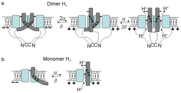
Channel opening in monomeric and dimeric HV channels. (a) Dimeric HV channel with dimer interactions between transmembrane domains and in the cytosolic domains as shown earlier9-11. Each subunit has its own proton permeation pathway as shown previously9-11. The activation movement of the two S4s are assumed to be independent in the two subunits. In this simple model, one S4 in the resting position inhibits the proton currents through both subunits. Not until both S4s have activated can the proton current flow through both subunits. (b) In monomeric HV channel (ΔNΔC construct), the activation of one S4 is enough to allow the proton flow, because there is no inhibition from a second subunit.
More complex allosteric models with separate S4 and channel opening steps could also explain our findings. For example, our findings can be reproduced by allosteric models that, in addition to the outward S4 movement measured by S242C fluorescence, also have a second cooperative opening conformational change that must occur in each subunit to open the proton permeation pathway (Supplementary Fig. 7). In these allosteric models, the rate limiting step for channel opening is the outward movement of the two S4s and not the opening conformational change. This cooperative opening conformational change is inhibited when one or both of the S4s in a dimeric channel are not activated (Supplementary Fig. 7a). In a monomeric ΔNΔC HV channel, the movement of S4 in the subunit is enough to allow for channel opening, because there is no inhibitory interaction from another subunit to prevent the opening conformational change (Supplementary Fig. 7b; compare our experimental data in Fig. 4c with simulation in Supplementary Fig. 7d).
The mechanism for the strong inhibition or cooperativity between subunits is not clear, but it might be steric clashes between the two subunits preventing opening of either channel unless both S4s are activated (Fig. 6a).
In conclusion, we have here shown data that are consistent with that S4 functions as the voltage sensor in HV channels and that, in a dimeric HV channel, S4 in both subunits have to move to activate the two proton permeation pathways. In contrast, if HV subunits are prevented from dimerizing, then the movement of a single S4 is sufficient to activate the proton permeation pathway in that subunit. These results show that there is strong cooperativity between subunits in dimeric HV channels.
Supplementary Material
Acknowledgements
We thank Drs. K. Magleby, S. Rebolledo, and F. Elinder for constructive criticism. This work was supported by the National Institutes of Health NS051169 (H. P. L.).
Appendix
Methods
Mutagenesis and expression of Ci-HV channels
We performed site-directed mutagenesis, in vitro transcription of cRNA, and injection of cRNA encoding the Ciona Ci-VSOP (here called Ci-HV) into Xenopus Laevis oocytes as described previously4, 33. The ΔNΔC Ci-HV was constructed with a stop codon at Val270 and initiator methionine replacing Glu129.
Cysteine accessibility measurements in TEVC and patch clamp recording
We performed cysteine accessibility to MTS reagents in excised inside-out patch clamp and two-electrode voltage clamp (TEVC) recordings as described earlier. Solutions for TEVC contained 88 mM NaCl, 1 mM KCl, 1 mM MgCl2, 1 mM CaCl2, and 100 mM HEPES (pH = 7.4). We injected oocytes with 50 nl of 1M HEPES (pH = 7.0) to minimize pH changes due to the proton currents. This results in approximately 100 mM HEPES in the cytosol. Note that the injection of 1M HEPES (pH = 7.0) into the oocytes does not assure that inside the oocyte the pH = 7.0. Variability in the absolute reversal potential was seen from oocyte to oocyte. Our recordings only show that the 1M HEPES injection prevents the pH from changing significantly by the proton currents, because the reversal potential does not change in response to different voltage steps. Solutions for excised patch recordings contained 100 mM HEPES, 2 mM MgCl2, and 1 mM EGTA (pH = 7 with NMDG) in both pipette and bath. To increase the current amplitude for cysteine mutations, we used pHi =5.5 in some recordings. Fresh MTS solutions were made from frozen stocks just before application. We tested the diffusion access to the patch with a rapid solution exchanger that changed the internal pH from 7.0 to 5.5, which increases the current substantially13. Only patches where solution exchange was faster than 100 ms were used to determine rate of MTS modification13.
VCF recordings
We performed VCF experiments as described previously40. Briefly, we labeled oocytes for 30 min with 100 μM Alexa-488 maleimide (Molecular Probes) in Na+ Ringer's solution. Fluorescence was monitored through a FITC filter cube: exciter, HQ480/40; dichroic, Q505LP; and emitter, HQ535/50. Fluorescence intensities were low-pass filtered at 200-500 Hz and digitized at 1 kHz. For careful kinetic comparison of fluorescence and proton currents, we injected 50 nl of 1M HEPES (pH = 7.0) into each oocyte to avoid pH changes due to the proton efflux. This results in approximately 100 mM HEPES in the cytosol. We also added 100 mM HEPES (pH = 7.4) to the external solutions for these recordings. Currents were leak subtracted off-line, assuming ohmic leak and using currents from potentials between −80 and −40 mV. To compare the kinetics of the fluorescence (F) and the currents (I), we fit the later half of the current and fluorescence traces to single exponentials and normalized them to their steady-state amplitudes. The normalized fluorescence traces were raised to the power-of-two (F2) to compare the kinetics of F, F2, and I from monomeric and dimeric HV channels.
Limiting slope measurements
To measure the limiting slope, we used slow voltage ramps (1 mV/s) from a holding potential of −60 mV to 0 mV and then ramp back to −60 mV. The current-voltage curves were identical during the up and down ramps, showing that the channels are at gating equilibrium at all voltages. We calculated conductance versus voltage, G(V), curves from the ramps by dividing the currents by (V−Erev) and plotted in a semilogarithmic plot. At low open probabilities the slope is proportional to the number of equivalent gating charge15, 19, 36, 37 in wt and mutated HV channels. The currents at the foot of the G(V) are very small, because the foot of the G(V) in HV channels is very close to the proton equilibrium potential EH 1, 38. Changing the pH gradient will not increase the currents very much at the foot of the G(V), because the voltage dependence of HV channels will shift almost as much as the EH 1, 38. In some experiments to increase the driving force and the size of the currents at low open probabilities, we applied 100 μM Zn2+ which shifts the G(V) by +30 mV without shifting the EH 1, 4. This allowed us to measure the conductance at lower open probabilities. No difference in the slope factor was found between experiments with and without Zn2+. All experiments shown are recorded with 0 Zn2+.
FRET measurements
We performed FRET measurements as described previously41, 42. Briefly, we labelled approximately 20% of the ΔNΔC S242C subunits in an oocyte with the donor fluorophore Alexa488-Maleimide. A donor-only fluorescence spectrum was measured on a Zeiss LSM 510 inverted confocal microscope with a META spectral detector using 488-nm excitation. The oocyte was subsequently labelled to saturation with TMR-MTS (2-((5(6)-tetramethylrhodamine) carboxylamino) ethyl-methanethiosulfonate)) acceptor fluorophore and a second fluorescence (donor + acceptor) spectrum was measured. We determined the FRET efficiency E by the donor quenching method measured at 510 nm. The decrease of donor fluorescence was measured at 510 nm because, at this wavelength, the oocyte endogenous fluorescence and the acceptor fluorescence were negligible when excited with a 488 nm laser 41, 42.
Footnotes
Author contributions: CG, BD, HPK, and HPL designed research, performed research, analyzed data, and wrote the paper.
Competing interest statement: The authors declare that they have no competing financial interests.
References
- 1.Decoursey TE. Voltage-gated proton channels and other proton transfer pathways. Physiol Rev. 2003;83:475–579. doi: 10.1152/physrev.00028.2002. [DOI] [PubMed] [Google Scholar]
- 2.Okamura Y. Biodiversity of voltage sensor domain proteins. Pflugers Arch. 2007;454:361–371. doi: 10.1007/s00424-007-0222-6. [DOI] [PubMed] [Google Scholar]
- 3.Ramsey IS, Moran MM, Chong JA, Clapham DE. A voltage-gated proton-selective channel lacking the pore domain. Nature. 2006;440:1213–1216. doi: 10.1038/nature04700. [DOI] [PMC free article] [PubMed] [Google Scholar]
- 4.Sasaki M, Takagi M, Okamura Y. A voltage sensor-domain protein is a voltage-gated proton channel. Science. 2006;312:589–592. doi: 10.1126/science.1122352. [DOI] [PubMed] [Google Scholar]
- 5.Hille B. Ion Channels of Excitable Membranes. Sinauer Associates, INC; Sunderland, MA: 2001. [Google Scholar]
- 6.Jiang Y, et al. X-ray structure of a voltage-dependent K+ channel. Nature. 2003;423:33–41. doi: 10.1038/nature01580. [DOI] [PubMed] [Google Scholar]
- 7.Long SB, Campbell EB, Mackinnon R. Crystal structure of a mammalian voltage-dependent Shaker family K+ channel. Science. 2005;309:897–903. doi: 10.1126/science.1116269. [DOI] [PubMed] [Google Scholar]
- 8.Long SB, Tao X, Campbell EB, MacKinnon R. Atomic structure of a voltage-dependent K+ channel in a lipid membrane-like environment. Nature. 2007;450:376–382. doi: 10.1038/nature06265. [DOI] [PubMed] [Google Scholar]
- 9.Koch HP, et al. Multimeric nature of voltage-gated proton channels. Proceedings of the National Academy of Sciences of the United States of America. 2008;105:9111–9116. doi: 10.1073/pnas.0801553105. [DOI] [PMC free article] [PubMed] [Google Scholar]
- 10.Tombola F, Ulbrich MH, Isacoff EY. The voltage-gated proton channel Hv1 has two pores, each controlled by one voltage sensor. Neuron. 2008;58:546–556. doi: 10.1016/j.neuron.2008.03.026. [DOI] [PMC free article] [PubMed] [Google Scholar]
- 11.Lee SY, Letts JA, Mackinnon R. Dimeric subunit stoichiometry of the human voltage-dependent proton channel Hv1. Proceedings of the National Academy of Sciences of the United States of America. 2008;105:7692–7695. doi: 10.1073/pnas.0803277105. [DOI] [PMC free article] [PubMed] [Google Scholar]
- 12.Aggarwal SK, MacKinnon R. Contribution of the S4 segment to gating charge in the Shaker K+ channel. Neuron. 1996;16:1169–1177. doi: 10.1016/s0896-6273(00)80143-9. [DOI] [PubMed] [Google Scholar]
- 13.Larsson HP, Baker OS, Dhillon DS, Isacoff EY. Transmembrane movement of the shaker K+ channel S4. Neuron. 1996;16:387–397. doi: 10.1016/s0896-6273(00)80056-2. [DOI] [PubMed] [Google Scholar]
- 14.Mannuzzu LM, Moronne MM, Isacoff EY. Direct physical measure of conformational rearrangement underlying potassium channel gating. Science. 1996;271:213–216. doi: 10.1126/science.271.5246.213. [DOI] [PubMed] [Google Scholar]
- 15.Seoh SA, Sigg D, Papazian DM, Bezanilla F. Voltage-sensing residues in the S2 and S4 segments of the Shaker K+ channel. Neuron. 1996;16:1159–1167. doi: 10.1016/s0896-6273(00)80142-7. [DOI] [PubMed] [Google Scholar]
- 16.Yusaf SP, Wray D, Sivaprasadarao A. Measurement of the movement of the S4 segment during the activation of a voltage-gated potassium channel. Pflugers Arch. 1996;433:91–97. doi: 10.1007/s004240050253. [DOI] [PubMed] [Google Scholar]
- 17.Schoppa NE, McCormack K, Tanouye MA, Sigworth FJ. The size of gating charge in wild-type and mutant Shaker potassium channels. Science. 1992;255:1712–1715. doi: 10.1126/science.1553560. [DOI] [PubMed] [Google Scholar]
- 18.Zagotta WN, Hoshi T, Dittman J, Aldrich RW. Shaker potassium channel gating. II: Transitions in the activation pathway. The Journal of general physiology. 1994;103:279–319. doi: 10.1085/jgp.103.2.279. [DOI] [PMC free article] [PubMed] [Google Scholar]
- 19.Gonzalez C, Rosenman E, Bezanilla F, Alvarez O, Latorre R. Modulation of the Shaker K(+) channel gating kinetics by the S3-S4 linker. The Journal of general physiology. 2000;115:193–208. doi: 10.1085/jgp.115.2.193. [DOI] [PMC free article] [PubMed] [Google Scholar]
- 20.Baker OS, Larsson HP, Mannuzzu LM, Isacoff EY. Three transmembrane conformations and sequence-dependent displacement of the S4 domain in shaker K+ channel gating. Neuron. 1998;20:1283–1294. doi: 10.1016/s0896-6273(00)80507-3. [DOI] [PubMed] [Google Scholar]
- 21.Mannuzzu LM, Isacoff EY. Independence and cooperativity in rearrangements of a potassium channel voltage sensor revealed by single subunit fluorescence. The Journal of general physiology. 2000;115:257–268. doi: 10.1085/jgp.115.3.257. [DOI] [PMC free article] [PubMed] [Google Scholar]
- 22.Pathak M, Kurtz L, Tombola F, Isacoff E. The cooperative voltage sensor motion that gates a potassium channel. The Journal of general physiology. 2005;125:57–69. doi: 10.1085/jgp.200409197. [DOI] [PMC free article] [PubMed] [Google Scholar]
- 23.Schoppa NE, Sigworth FJ. Activation of Shaker potassium channels. III. An activation gating model for wild-type and V2 mutant channels. The Journal of general physiology. 1998;111:313–342. doi: 10.1085/jgp.111.2.313. [DOI] [PMC free article] [PubMed] [Google Scholar]
- 24.Zagotta WN, Hoshi T, Aldrich RW. Shaker potassium channel gating. III: Evaluation of kinetic models for activation. The Journal of general physiology. 1994;103:321–362. doi: 10.1085/jgp.103.2.321. [DOI] [PMC free article] [PubMed] [Google Scholar]
- 25.Chapman ML, VanDongen HM, VanDongen AM. Activation-dependent subconductance levels in the drk1 K channel suggest a subunit basis for ion permeation and gating. Biophysical journal. 1997;72:708–719. doi: 10.1016/s0006-3495(97)78707-1. [DOI] [PMC free article] [PubMed] [Google Scholar]
- 26.Zheng J, Sigworth FJ. Selectivity changes during activation of mutant Shaker potassium channels. The Journal of general physiology. 1997;110:101–117. doi: 10.1085/jgp.110.2.101. [DOI] [PMC free article] [PubMed] [Google Scholar]
- 27.DeCoursey TE, Cherny VV. Deuterium isotope effects on permeation and gating of proton channels in rat alveolar epithelium. The Journal of general physiology. 1997;109:415–434. doi: 10.1085/jgp.109.4.415. [DOI] [PMC free article] [PubMed] [Google Scholar]
- 28.Mannikko R, Elinder F, Larsson HP. Voltage-sensing mechanism is conserved among ion channels gated by opposite voltages. Nature. 2002;419:837–841. doi: 10.1038/nature01038. [DOI] [PubMed] [Google Scholar]
- 29.Yang N, George AL, Jr., Horn R. Molecular basis of charge movement in voltage-gated sodium channels. Neuron. 1996;16:113–122. doi: 10.1016/s0896-6273(00)80028-8. [DOI] [PubMed] [Google Scholar]
- 30.Pathak MM, et al. Closing in on the resting state of the Shaker K(+) channel. Neuron. 2007;56:124–140. doi: 10.1016/j.neuron.2007.09.023. [DOI] [PubMed] [Google Scholar]
- 31.Campos FV, Chanda B, Roux B, Bezanilla F. Two atomic constraints unambiguously position the S4 segment relative to S1 and S2 segments in the closed state of Shaker K channel. Proceedings of the National Academy of Sciences of the United States of America. 2007;104:7904–7909. doi: 10.1073/pnas.0702638104. [DOI] [PMC free article] [PubMed] [Google Scholar]
- 32.Bezanilla F. The voltage sensor in voltage-dependent ion channels. Physiol Rev. 2000;80:555–592. doi: 10.1152/physrev.2000.80.2.555. [DOI] [PubMed] [Google Scholar]
- 33.Bruening-Wright A, Elinder F, Larsson HP. Kinetic Relationship between the Voltage Sensor and the Activation Gate in spHCN Channels. The Journal of general physiology. 2007;130:71–81. doi: 10.1085/jgp.200709769. [DOI] [PMC free article] [PubMed] [Google Scholar]
- 34.Cha A, Bezanilla F. Characterizing voltage-dependent conformational changes in the Shaker K+ channel with fluorescence. Neuron. 1997;19:1127–1140. doi: 10.1016/s0896-6273(00)80403-1. [DOI] [PubMed] [Google Scholar]
- 35.Cha A, Snyder GE, Selvin PR, Bezanilla F. Atomic scale movement of the voltage-sensing region in a potassium channel measured via spectroscopy. Nature. 1999;402:809–813. doi: 10.1038/45552. [DOI] [PubMed] [Google Scholar]
- 36.Gonzalez C, Morera FJ, Rosenmann E, Alvarez O, Latorre R. S3b amino acid residues do not shuttle across the bilayer in voltage-dependent Shaker K+ channels. Proceedings of the National Academy of Sciences of the United States of America. 2005;102:5020–5025. doi: 10.1073/pnas.0501051102. [DOI] [PMC free article] [PubMed] [Google Scholar]
- 37.Sigg D, Bezanilla F. Total charge movement per channel. The relation between gating charge displacement and the voltage sensitivity of activation. The Journal of general physiology. 1997;109:27–39. doi: 10.1085/jgp.109.1.27. [DOI] [PMC free article] [PubMed] [Google Scholar]
- 38.Cherny VV, Markin VS, DeCoursey TE. The voltage-activated hydrogen ion conductance in rat alveolar epithelial cells is determined by the pH gradient. The Journal of general physiology. 1995;105:861–896. doi: 10.1085/jgp.105.6.861. [DOI] [PMC free article] [PubMed] [Google Scholar]
- 39.Almers W. Gating currents and charge movements in excitable membranes. Reviews of physiology, biochemistry and pharmacology. 1978;82:96–190. doi: 10.1007/BFb0030498. [DOI] [PubMed] [Google Scholar]
- 40.Larsson HP, Tzingounis AV, Koch HP, Kavanaugh MP. Fluorometric measurements of conformational changes in glutamate transporters. Proceedings of the National Academy of Sciences of the United States of America. 2004;101:3951–3956. doi: 10.1073/pnas.0306737101. Epub 2004 Mar 3954. [DOI] [PMC free article] [PubMed] [Google Scholar]
- 41.Koch HP, Hubbard JM, Larsson HP. Voltage-independent sodium-binding events reported by the 4B-4C loop in the human glutamate transporter EAAT3. The Journal of biological chemistry. 2007 doi: 10.1074/jbc.M704087200. [DOI] [PubMed] [Google Scholar]
- 42.Koch HP, Larsson HP. Small-scale molecular motions accomplish glutamate uptake in human glutamate transporters. J Neurosci. 2005;25:1730–1736. doi: 10.1523/JNEUROSCI.4138-04.2005. [DOI] [PMC free article] [PubMed] [Google Scholar]
Associated Data
This section collects any data citations, data availability statements, or supplementary materials included in this article.