Abstract
Micro photopatterning (µPP) has been developed to rapidly test and generate different patterns for extracellular matrix adsorption without being hindered with the process of making physical stamps through nanolithography techniques. It uses two-photon excitation guided through a point-scanning confocal microscope to locally photoablate poly(vinyl) alcohol (PVA) thin films in user-defined computer-controlled patterns. PVA thin films are ideal for surface blocking, being hydrophilic substrates that deter protein adsorption and cell attachment. Because gold substrates are not used during µPP, all live-cell fluorescent imaging techniques including total internal reflection fluorescence microscopy of GFP–linked proteins can be performed with minimal loss of fluorescence signal. Furthermore, because µPP does not require physical stamps for pattern generation, multiple ECMs or other proteins can be localized within microns of each other. This unit details the setup of µPP as well as giving troubleshooting techniques.
Keywords: Micro photopatterning, micropatterning, extracellular matrix, two-photon confocal microscopy, photoablation, polyvinyl alcohol, thin film
This unit describes the generation of micropatterned substrates using a direct-writing method known as micro photopatterning or µPP. Micropatterning of extracellular matrix (ECM) components, where ECM proteins are applied to a two-dimensional surface in a specified pattern, has been an important technique for understanding how cells respond and react to their physical surroundings. The most common manner in which to generate micropatterns is through the process known as microcontact printing or µCP, where a physical stamp is used to “ink” ECM patterns onto a gold-coated coverslip (Lehnert et al., 2003). More details about this process can be found under background information in the Commentary section.
While µCP has been refined and can now generate sub micron-sized patterns (Lehnert et al., 2003), it has several limitations. One major limitation is that the patterns of a master cannot be readily changed. This requires a new master for each new pattern or stamp. A second limitation is the use of gold for alkanethiol attachment. Being an electron-dense metal, gold strongly quenches green fluorescent protein (GFP) fluorescence, leaving the ability to perform live-cell fluorescence imaging nearly impossible.
Here we describe in detail how to generate ECM micropatterned glass-bottomed dishes or coverslips using micro photopatterning that bypasses many of the issues associated with other micropatterning techniques (Doyle et al., 2009). This technique utilizes high-powered two-photon (TP) laser excitation channeled through a point scanning confocal microscope in order to physically ablate or remove a thin film of poly(vinyl) alcohol (PVA). This exposes the underlying glass surface to which ECM proteins can directly attach. PVA’s high hydrophilicity and relative inertness make it an optimal candidate for deterring protein adsorption to non-ablated regions of the thin film. Furthermore, PVA’s high refractive index (~1.5) allows for all fluorescence techniques, including total internal reflection fluorescence, even through nonablated regions of the film. In addition, by performing several rounds of µPP in series, multiple proteins can be deposited locally within microns of each other.
STRATEGIC PLANNING
While µPP is fairly straightforward methodology it does call for experience and knowledge using a confocal microscope. While the day-to-day processing requires little expense, two important pieces of equipment are necessary: 1) A spincoater to evenly and thinly distribute PVA over the glass surface, and 2) a two-photon laser point scanning confocal microscope to locally ablate patterns in the PVA thin film. While each piece of equipment is an added expense (spincoater: ~$6,000–12,000, Zeiss 510 LSM NLO system: >$500,000) both can be found on most university campuses. Check with Material Science or Bioengineering departments for spincoating devices, and Biology to Physics departments for availability of two-photon confocal systems. Throughout this chapter we refer to the Zeiss 510 LSM NLO system (NLO stands for NonLinear Optics) as to the confocal and the AIM software version 4.2 which runs the microscope. It is assumed that the user has basic knowledge using the software in expert mode. Although not described here, it is our view that with slight alterations to the below protocols, other two-photon confocal types (i.e. Olympus) could be used to attain local ablation of the PVA thin film.
The process of µPP can be broken down into five stages: 1) glass surface activation, 2) PVA thin film deposition, 3) photoablation, 4) surface quenching, and 5) ECM adsorption. Each part of the process can be a stopping point with the steps that follow being up to several days or even weeks apart. For example, following glass surface activation, dishes/coverslips can be kept desiccated for over month at 4°C, which allows you to generate 30 or more dishes at a time, but other steps can be performed in smaller batches more frequently. Below is a table showing the longevity of samples after their given stage of processing. The following sections will describe in detail each of the protocols associated with the stages as well as provide background information and troubleshooting tips.
Table 1.
Longevity of samples after the given stage of processing
| Stage | Time (days) |
|---|---|
| 1) Glass surface activation | 30+ |
| 2) PVA thin film deposition | 7–14 |
| 3) Photoablation | 30+ |
| 4) Quenching | 30+ |
| 5) ECM adsorption | 1–3 |
Basic Protocol 1
ACTIVATION OF THE GLASS SURFACE
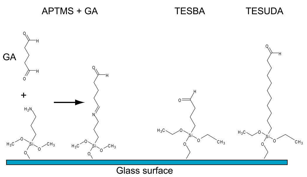
This protocol describes how to prepare the glass surface for direct conjugation to the PVA thin film. The first order of business is to clean the glass surface of any organic residues through acid washing. This is crucial so the silanes are uniformly distributed over the glass to provide covalent attachment of the PVA thin film. The term “activated glass” or “activation” here refers to adding a reactive aldehyde group conjugated directly to the glass surface, through silanes. The aldehydes can react directly with hydroxyl groups found on the PVA polymer and hence the thin film generated in later steps is covalently attached to the glass. The silanes in question are (3-aminopropl)trimethoxysilane (APTMS), Triethoxysilylbutraldehyde (TESBA), and 11-(Triethoxysilyl)undecanal (TESUDA). The first is an amino-terminated silane which requires glutaraldehyde for “activation”, while the latter two are both aldehyde terminated (Figure 1). Protocols for using both types are detailed below. Caution should be used when handling silanes; they can cause severe burns and damage many surfaces. Note: After the completion of each process (i.e. acid washing, silanization, etc.) it is important to visually inspect all dishes under a microscope with a 10X objective to observe if there are any imperfections in the surface. If there are, it is best to discard the dishes before any further steps.
Figure 1.
Schematic of APTMS, TESBA, and TESUDA conjugated to a glass surface. The addition of glutaraldehyde (GA) to APTMS-coated glass results in “activation” by attachment to the free amino group, leaving a free aldehyde to react with PVA during spin coating.
Materials
Tygon™ tubing (R-3603)
1000 µl barrier filter pipet tips
30 MatTek glass-bottomed dishes P35G-1.5–10-C
Carrying tray
50% nitric acid
Automatic pipetter
2000 ml beaker
Deionized or distilled water (dH2O)
(3-aminopropyl)trimethoxysilane (APTMS: 97% or higher) (Gelest)
Scale
Scintillation vials or other small glass containers
Pasteur pipettes
200 mM NaOH solution
50% glutaraldehyde (Electron Microscopy Sciences)
Aldex
Drying oven
Drierite™
Nalgene 500ml screw top or other similar containers for storage
Preparing the glass surface for silanization
-
1.
Before starting the acid washing create a compressed air blower using three feet of Tygon tubing and a 1000 µl barrier filter pipet tip. Connect one end of the tubing to a low pressure air jet (commonly found on most laboratory benches). Insert the pipet tip into the other end, tip out. Alternatively, this can be attached to a compressed air or nitrogen tank. This will used throughout the process to dry the dishes. Note: use low pressure for drying, ¼ to 1/3 of the way open or under 10 psi.
-
2.
In a fume hood, arrange 30 MatTek dishes on tray. Using a Pasteur pipette fit into an automatic pipetter, add a small amount of 50% Nitric acid to each dish, just enough to cover the glass area, usually between 300–500 µl. Incubate for 25 minutes at room temperature.
-
3.
After time has elapsed, place dishes in a large 2000 ml beaker and rinse with deionized or distilled water, under continuous flow for a minimum of 4 hours or overnight. Be sure that dishes are not floating.
-
4.
Remove dishes from water and aspirate remaining water from dishes. Arrange dishes on a tray again and add 300–500 µl of 200 mM NaOH to each dish and incubate for 15 minutes. This step helps to exchange H+ residues associating with the glass from the acid washing and neutralizing or replacing them with OH− which is more conducive for the binding of the methoxy or ethoxy portion of the silane.
-
5.
Rinse dishes 2 times with deionized or distilled water, then dry under compressed air (device created in step one).
Silanization of glass surfaces
-
6.
Place a scintillation vial on a scale, tare, and weigh out 1% APTMS (w/v). Caution: silanes corrode metals, plastics and all organics. Only use glass for transferring and wear chemical resistant gloves when handling. Insert a glass Pasteur pipette into the APTMS and tilt container to 45°. Capillary action should bring the APTMS into the pipette. Place your gloved finger on the top open-end of the pipette, transfer and release a total of 100 mg. Add 9900 µl of dH2O to the scintillation vial. Replace cap and mix gently and incubate for 1 minute at room temperature.
-
7.
Add ~300–500 µl of the 1% APTMS solution to each dish, only covering the glass portion. Incubate for 5 minutes.
-
8.
Dispose of APTMS properly (contact your chemical safety officer for the proper disposal). Rinse 2 times with dH2O over 10 minutes.
-
9.
Aspirate dH2O and dry dishes with compressed air. Replace dish lids and incubate at 65°C in a drying oven for a minimum of 3-hours. This step cures the silanes. They can also be left desiccated at room temperature overnight and achieve the same level of curing. Note: Incubation above 65°C leads to warping of the dishes.
Activating of amino-terminated silanes with glutaraldehyde
-
10.
To convert this amino-terminated silane into an active aldehyde, glutaraldehyde (a bi-functional aldehyde) is added to react directly with the amino group. Mix 100 µl of 50% glutaraldehyde with 9900 µl dH2O to make a 0.5% glutaraldehyde solution. Add ~300–500 µl of the solution to the glass surface only. Incubate for 30 minutes at room temperature.
-
11.
Remove glutaraldehyde solution and discard properly in Aldex (see note below). Rinse dishes in dH2O three times over 20 minutes. Aspirate dH2O and blow dry surface again. Store at 4°C in a desiccated storage container (add Drierite to the container bottom or to a small vial placed inside it); it can be stored before use for around 1 month. Note: glutaraldehyde should be discarded of properly. Aldex is used to inactivate the reactive aldehydes allowing for proper disposal.
Alternative protocol 1
USING ALDEHYDE TERMINATED SILANES FOR SURFACE ACTIVATION
In order to bypass the last two steps of Protocol 1, TESBA or TESUDA, which are already terminated in a reactive aldehyde group, can be used. Both are triethoxysilanes which renders them water insoluble and requires ethanol as the solvent. The materials shown below are in addition to those shown in the above protocol, minus the Aldex, and glutaraldehyde. Changes to the steps shown above have been bolded.
Materials
Triethoxysilylbutraldehyde (TESBA) or 11-(Triethoxysilyl)undecanal (TESUDA) (Gelest)
Ethanol (200 proof)
-
1.
Follow steps 1 through 5 for acid washing of glass bottomed dishes shown in the basic protocol #1 above.
-
6.
Place a scintillation vial on a scale, tare, and weigh out 1% of either silane (w/v). Insert a glass Pasteur pipette into the silanes and tilt container to 45°. Capillary action should bring the silanes into the pipette. Place your gloved finger on the top open-end of the pipette, transfer and release a total of 100 mg. Add 9900 µl of 100% ethanol to the scintillation vial. Mix gently with the cap on and incubate for 5 minutes at room temperature.
-
7.
Add ~300–500 µl of the 1% silane solution to each dish, only covering the glass portion. Incubate for 5 minutes.
-
8.
Dispose of the silanes properly (contact your chemical safety officer for the proper disposal). Rinse twice with 100% ethanol followed by a single rinse with dH2O for 2 minutes.
-
9.
Aspirate dH2O and dry dishes with compressed air. Replace dish lids and incubate at 65°C in a drying oven for a minimum of 3-hours. This step cures the silanes. They can also be left desiccated at room temperature overnight to achieve the same level of curing. Above 65°C leads to warping the dishes.
-
10.
Store at 4°C in a desiccated storage container (add Drierite to the container bottom or to a small vial placed inside it) for up to 1 month.
Basic Protocol 2
GENERATING PVA THIN FILMS
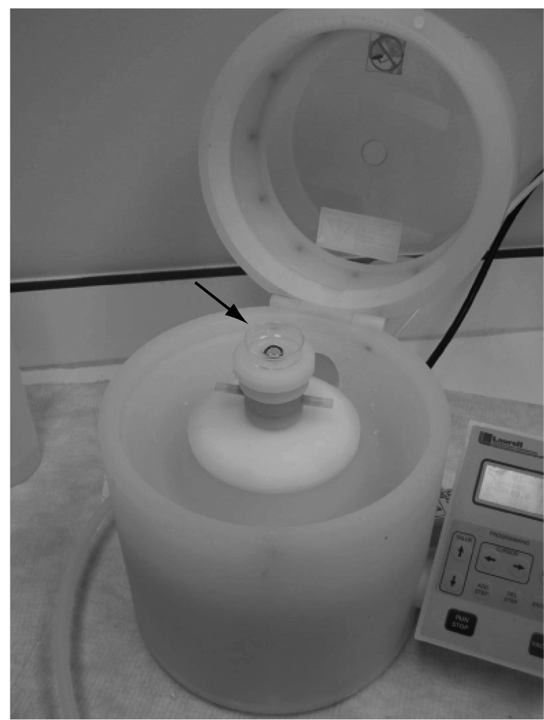
Here we describe the mixing of the PVA solution and spinning-coating it into a thin film on the activated glass dishes prepared in basic protocol #1. Spincoating is a process by which a solution (in this case PVA) is thinned evenly across a surface using centripetal force. This is often used in the semiconductor industry to apply agents to silicon wafers. A flat glass disc or dish is attached via vacuum suction to a central “chuck” (Figure 2). Chucks come in many sizes to fit the size of the disc/dish. The vacuum secures the disc from moving during spinning. Most Spincoaters require a vacuum source (in our case a gel pump) and a source of high pressure air, (a normal compressed air cylinder). The latter is to keep liquids and other materials from coating the rotor.
Figure 2.
Laurel Technologies Spincoater with an “activated” MatTek dish in position before spincoating PVA/HCl solution. The chuck (arrow) can be changed according to the size required for the dish/disc being spun.
Materials
5–10 MatTek dishes with activated glass surface from protocol #1
Poly(vinyl) alcohol powder (MW between 13,00 and 100,000; 98% hydrolyzed minimum, Sigma)
2N HCl
5M NaCl
dH2O
50ml conical tubes
Flea Micro™ magnetic stir bar (VWR)
50ml Steriflip™ (0.2 µm pore size)
400 ml glass beaker
Nalgene 500ml screw top or other similar containers for storage
Scintillation vial or 35mm tissue culture dish
Stirrer/Hotplate
High pressure compressed air source such as a compressed air cylinder
Gel vacuum pump
Spincoater with a chuck capable of accepting 50mm or smaller items (A WS-400B-6NPP/LITE spincoater from Laurel Technologies shown in figure 2 was used here)
Making the PVA solution
The PVA solution can be used repeatedly over a period of one week. We recommend making it fresh weekly.
-
1.
Add approximately 270 ml of water to a 400 ml glass beaker and begin heating on a stirring hot plate (medium-high heat).
-
2.
Weight out 2.835 grams of PVA into a 50 ml conical tube. With tube still on the scale bring the weight/volume up to 50 grams with dH2O. Add stir bar to conical tube.
-
3.
PVA will not go into solution until ~90°C. Loosen cap slightly and place PVA-containing tube into beaker of hot, near boiling water. The water line of beaker should be between the 35–40 ml lines on the conical tube. Turn on stirring mechanism to medium and continue heating until PVA goes into solution, approximately 10–15 minutes. Have the 50 ml Steriflip ™ ready.
-
4.
Inspect the PVA solution and be sure no PVA crystals/powder remains. When sure, immediately 0.2 µm filter the PVA solution into the Seriflip™ using vacuum The PVA must be hot (above 90°C) to filter. Once cooled, the viscosity of the solution increases and makes filtering nearly impossible.
-
5.
Allow the solution to cool to room temperature. Once cooled, transfer 8876 µl to a new 50 ml conical tube. To this add 1124 µl of 2N HCl and mix by vortexing. This acidified PVA solution can now be used for spincoating.
Spincoating thin films of PVA
For spincoating we have found that a relatively short spin of 40 seconds at a high velocity (7000 rpm) works best for generating a thin coating of PVA, with few imperfections. Acceleration of the spincoater is also important: 550 rpm gets the dish up to speed within 18 seconds. However, you may need to adjust all variables (time, velocity and acceleration) to determine which best suits your needs.
-
6.
Retrieve 5–6 of the “activated” MatTek dishes that were stored desiccated at 4°C.
-
7.
Add ~300–500 µl of the PVA/HCl solution with a pipetter to the glass surfaces of the dishes and incubate for 5 minutes. Be sure to completely cover the glass area.
-
8.
Center a single dish on the chuck of the spincoater. Follow the manufacturer's instructions for operation. Pull a vacuum and turn on your compressed air. Initiate your spin. When finished, repeat for each dish.
-
9.
Add 2–3 mls of 5M NaCl to either a scintillation (no cap) vial or a 35 mm tissue culture dish and place in the storage container. Place dishes within the storage container and incubate a minimum of 2 hours before ablating. Store dishes within the container at 4°C for up to two weeks prior to photoablation. Note: High molarity or super-saturated salt solutions are effective in regulating humidity within a closed environment with each salt type maintaining a different relative humidity. For NaCl it is approximately 50–60%, which is optimal for reducing issues with PVA crystallization, and loss of surface hydrophilicity.
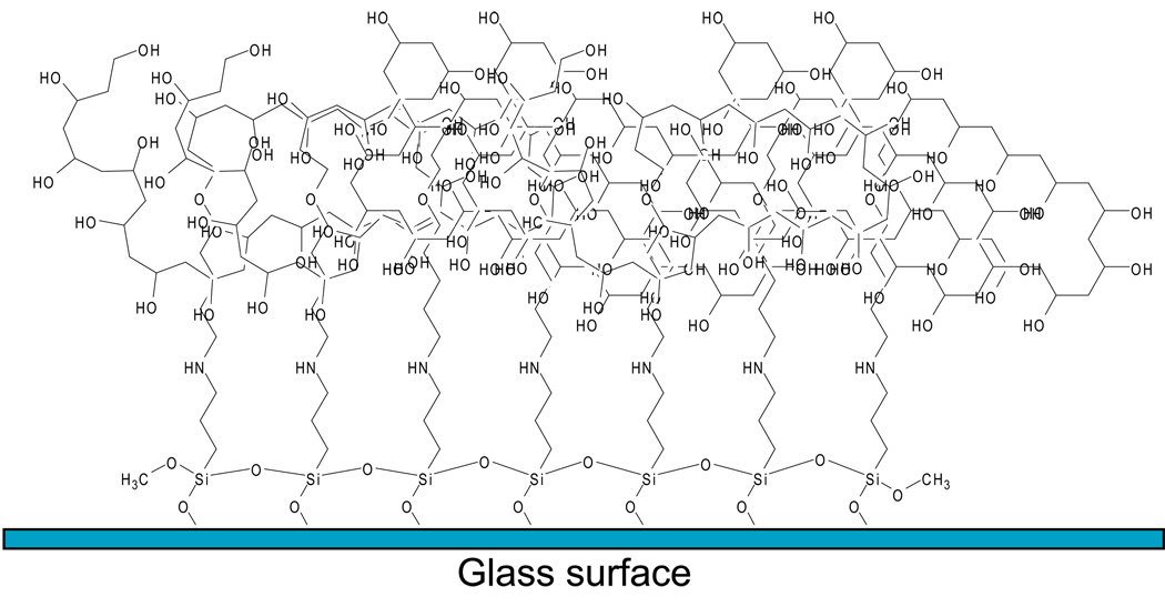
At this point in the processing the activated glass surface is now coated with a submicron (between ~100–200 nm) thin film of PVA which will deter protein adsorption and cell attachment (Figure 3).
Figure 3.
Representation of the PVA thin film generated on dishes following processing through protocol #2 using APTMS together with glutaraldehyde as the crosslinker.
Basic Protocol 3
PHOTOABLATION WITH TWO-PHOTON CONFOCAL MICROSCOPY
In this section the actual process of photoablation is discussed. It is divided into several sections for clarity. First the configuration settings for the confocal are addressed, followed by the pre-ablation setup and how to generate pattern templates. We then detail how to photoablate single fields of view (FOV) and finally how to automate the process using the multitime macro and tiling functions. Throughout this section and the ones that follow, we will often be referring to dialog boxes and buttons within the AIM software. The title of each dialog/button will be bolded for easier referencing. For all intents and purposes, the actual photoabation process merely utilizes the intrinsic capabilities of a point-scanning confocal microscope. However, the major difficulty is in setting the proper configurations to elicit localized ablation efficiently. Once configuring is complete the process can be performed with relative ease.
Materials
Zeiss 510 LSM NLO confocal microscope or later model with 1.5W minimum tunable two-photon titanium:Sapphire laser, and a 633nm HeNe2 laser (5mW power output)
63X oil immersion objective with numerical aperture of 1.3 or higher capable of NLO transmission
PVA thin film-coated MatTek dishes generated in protocol #2
Confocal microscope configuration set up
The following steps are meant to guide you through configuration setup and scan settings that are required for the ablation process. Throughout this section are screen shots of the AIM software (version 4.2) to help in understanding how and where to change settings (indicated by bolded numbers in figures). It is important to note that the direct light path from the TP laser to the confocal scan head should be aligned at least once a month. Ablation efficiency is greatly reduced when mirrors are misaligned. Have a qualified individual align the mirrors (microscope facility director, Zeiss service representative, etc.) at 755 nm before beginning the ablation process.
-
1.
Turn on the confocal and boot the computer: there is no need to ignite the mercury arc lamp since it is not used to find the thin film. Be sure to turn the two-photon laser from the standby to the on position.
-
2.
Open the AIM software in expert mode. Go into the Acquire menu and open the Laser window (Figure 4, 1; i.e., the inserted numeral 1 in Figure 4); turn on the 633 nm and tune the two-photon to 755 nm. In the same Acquire menu, select Configuration (Figure 4, 2). This will open up the configuration window (Figure 5). In Channel Mode Singletrack or Multitrack can be selected.
-
3.
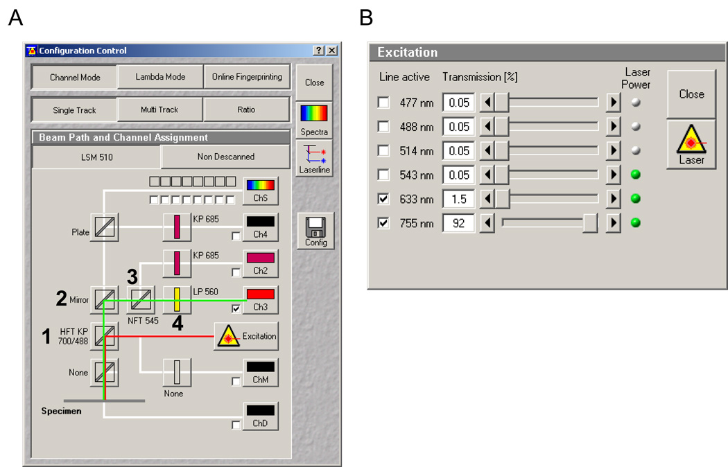
For the primary dichroic (Figure 5A) select the HFT KP 700/488 (1). This allows the near-infrared (NIR) light from the two-photon to be reflected to your sample. While the 633nm light is not properly matched for the dichroic, it provides back reflection of the glass/thin film interface, similar to backscatter, helping you find the appropriate Z-plane for ablation. Select photomultiplier tube or channel 3 (Ch3) and set the following filters along the light path illustrated below: Mirror (2), NFT 545 (3), and LP 560 (4). Set the 633 nm laser to 1.5% power and the 755 nm TP to ~90% by selecting Excitation, which opens the Excitation window (Figure 5B). Note: the percent power is a reflection of the total amount allowed through the AOTF or AOM for the 633 nm HeNe2 and the 755 nm TP, respectively. Using the TP at 90% does not affect the lifetime of the laser. Click on the Config button on the middle right-hand side of the window. Save the configuration at this point. You may want the title to be basic at this point. Later on, this basic version can be changed and saved to reflect your zoom and scan settings (discussed in the next few steps).
-
4.
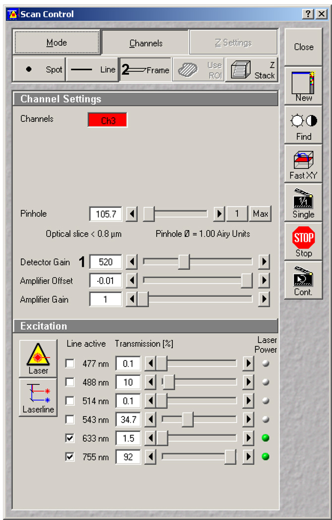
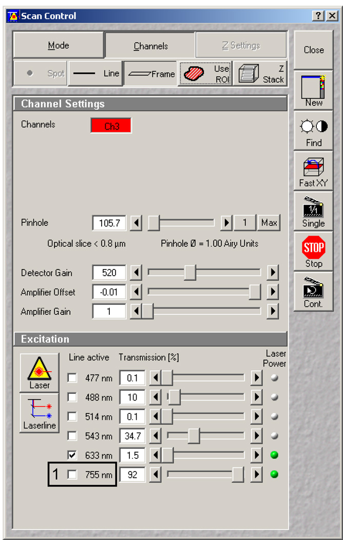
Now that you have created and saved the proper basic configuration, open the Scan window and select the Channels menu (Figure 6). Set the detector gain to approximately halfway up, in the low 500s (Figure 6, 1). Be sure that frame scan is selected (Figure 6, 2) and the pinhole is set to 1 Airy for a 63X objective.
-
5.
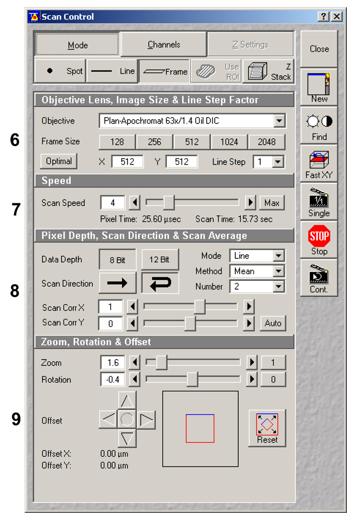
Select the Mode window (Figure 7). The Mode window is divided vertically into four separate control boxes: 1) objective, line stepping and frame control, 2) scan speed, 3) pixel depth, scan direction, and averaging, and 4) zoom, rotation and offset. Because of the complexity of this window, each control box will be addressed in separate steps below.
-
6.
Objective, line stepping and frame control (Figure 8): For µPP, this box is important for controlling the pixel size, which will impact the region of interest (ROI) template, how detailed or defined the ablation patterns are, as well as the total scan time (the larger the pixel array the longer the scan time). We have found that using a 512 × 512 array is a good intermediate (Figure 8, 1): fast scanning with a reasonably high level of detail. Line step should be 1 (Figure 8, 2). Objective can be varied but should be have a high numerical aperture (N.A), minimum of 1.0.
-
7.
Scan speed (Figure 9): This sets the relative rate of speed the galvanometric mirrors move and scan the FOV or the ablation area. As scan speed increases (Figure 9, 1) both pixel time and Scan time (Figure 9, 2 and 3, respectively) decrease. The Pixel Time (or dwell time) is the amount of time the laser dwells and any given pixel in the FOV. Since efficiency of the ablation process is directly dependent on the total amount of light energy (in µjoules/µm2), the dwell time will dependent on the total power output of the TP laser (in our case about 1200 mW at 755 nm). A scan speed of 4 using a 63X provides efficient ablation with our set up. Scan speed will need to be decreased when the pixel size changes, for instance, when a digital zoom is used to generate smaller patterns with the same objective lens. This will be discussed in later sections.
-
8.
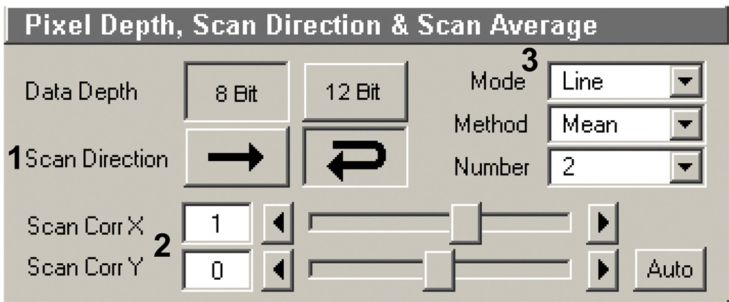
Pixel depth, scan direction, and averaging (Figure 10): Scan direction and scan average are equally important here. Choose to reverse scan direction (Figure 10, 1; reverse arrow). This decreases the scan rate by half when compared to the single direction. When choosing this a scan, the correction dialog is opened. This helps to align the scanning properly (Figure 10, 2; see your Zeiss representative or manual for more on how to do this). Scan average (Figure 10, 3) provides the same basic function it normally does when imaging: repeated scanning of the same line or frame in the FOV. However, instead of decreasing background noise it adds a second (or more) pass over the area being ablated. For example, increasing this number from 1 to 2 overall doubles the laser dwell time by performing a second pass. It will also double the scan time (from step 7). Leave the scanning in line mode. The method does not matter since you are not saving the image files.
-
9.
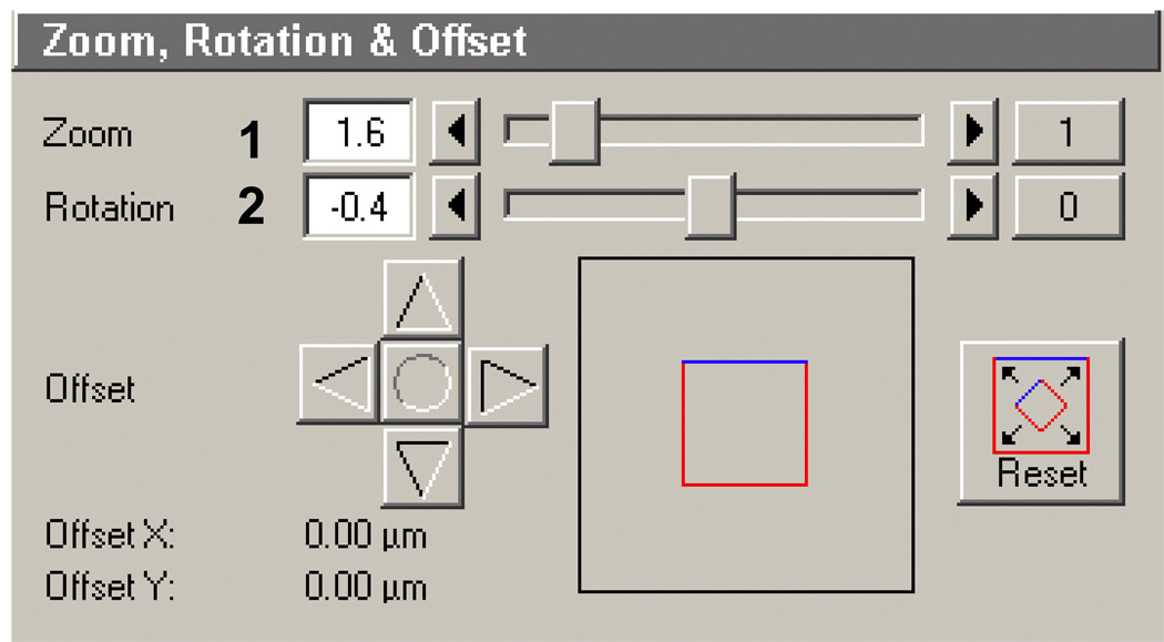
Zoom, rotation and offset (Figure 11): In this box you can set the appropriate zoom (Figure 11, 1). This is helpful if wanting to decrease the size of an entire ROI template. For example, you can generate a circle pattern with a diameter of 10 microns simply by zooming in by 2X with a ROI template containing a circle with a 20 micron diameter. Here it is set to 1.6, which when using a 63X objective is equivalent to 100X. This is not an optical or a true digital zoom: the same pixel array is scanned but simply in a smaller region on the galvanometric mirrors. Rotation (Figure 11, 2) is important only when generating multiple patterns (same or different) next to each other and comes into play in later sections when using the automated tiling function. In many confocals the galvometric mirrors are slightly offset from the true horizontal or vertical plane of the stage. By correcting the rotation for this offset, larger patterns (i.e. long lanes or lines) can be flawlessly connected and generated. Setting the proper rotation offset is discussed later in supporting protocol 1. FOV offset is normally not changed. Note: the Zoom function can also go below 1 to.7 giving you a larger FOV. However, the rotation dialog will be reset to 0 and cannot be changed.
Figure 4.
The LSM 510 AIM software expert mode window with Acquire menu open. All screen shots of the AIM software are courtesy of Carl Zeiss MicroImaging Inc..
Figure 5.
Configuration Control window screen shot for Zeiss’ AIM software (version 4.2). A) Line red depicts the light path from the lasers to the PVA-coated dish, while the green line illustrates the reflected light path from the dish to the channel 3 photomultiplier tube (Ch3). Numbers show the primary dichroic (1) mirror (2) and filters (3 and 4) required for obtaining a reflected light image of the thin film surface. B) The laser excitation panel with 633nm and 755nm TP settings.
Figure 6.
Scan Control window illustrating the Channels dialog panel.
Figure 7.
Scan Control window illustrating the Mode dialog panel. The four boxes within the panel are discussed in detail in the step numbered on the left side of the panel with enlarged images.
Figure 8.
Objective, line stepping and frame control box in the Scan control window of the AIM software.
Figure 9.
Scan speed box in the Scan control window of the AIM software.
Figure 10.
Pixel depth, scan direction, and averaging box in the Scan control window of the AIM software.
Figure 11.
Zoom, rotation and offset box in the Scan control window of the AIM software.
At this point the confocal configurations are properly set. Save the Configuration again in the Configuration control panel as you did in step 3 above.
Pre-ablation set up
While the previous section led you through the proper confocal configurations required for efficient ablation of the PVA thin film, this section will guide you through how to find the proper Z-plane to ablate the thin film, how to align the Z-plane and how to generate ROI templates for use in ablation. After these steps ablation can be performed.
-
10.
Bring your PVA thin film dishes in their container to room temperature. Place the dishes you will be patterning near or on the scope to allow them to acclimate to the temperature of the confocal since differences in oil, objective and dish temperature will cause focus drift. Boot the system as before in step 1, turning on the appropriate lasers. Clean the bottom of the dish with glass cleaner thoroughly and dry. Add a small drop of oil directly to the bottom of the dish and place it in the single dish holder. Note: Before proceeding, make sure the stage insert is clean and properly fit into the stage with all adjustment screws up (not contacting the stage plate).
-
11.
After loading the software, load the configuration for ablation saved in previous steps. Bring the 63X objective up to your sample using the course focus knobs until the oil hits the glass. Before using Fast XY to find your sample, be sure to inactivate the 755nm laser line in the Scan control window under the Channels panel (Figure 12, 1 black box). This is imperative since this amount of light will ablate the surface as soon as you reach the focal plane.
-
12.
Using the Fast XY function, begin scanning for the PVA thin film surface by rotating the fine focusing knob (up: clockwise on the right-hand side of the microscope). Do this at a moderate to fast pace moving 300–400 µm in about 10 seconds time. While doing this keep your eye on the monitor. When you reach or pass the focal plane it will appear as a bright line or set of lines on the screen in Fast XY mode (Figure 13A–B). Adjust the objective Z position until the nearly the entire FOV is in focus (Figure 13C). Once in focus you may need to adjust the PMT gain up or down depending on the brightness. The brightest Z-plane, which is the glass interface, should be near pixel saturation (~255 for an 8-bit image).
-
13.
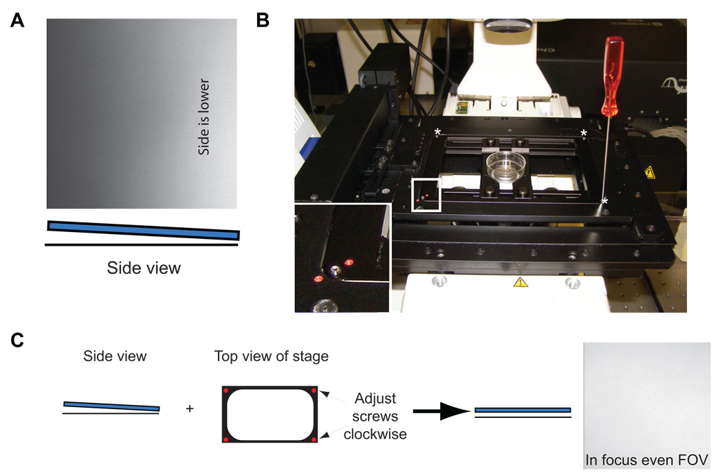
More often than not the FOV’s brightness is unevenly distributed, such as in Figure 14A, and requires adjustment since the TP light is maximally absorbed only at the focal plane. To adjust properly you first need to know which corner or edge is low. Adjust the focus so the focal plane is below the glass. Slowly raise the objective until you start to see brightness in the FOV: which ever area appears bright first is low and needs to be raised using the adjustment screws in the stage insert plate (Figure 14B). In the example in Figure 10A, both the upper right and lower right adjustment screws need to be turned clockwise, or screwed in to raise the stage up. Perform several half turns. The image should go black, indicating the stage has been adjusted. Refocus with the fine focusing knobs. Repeat this process until the FOV demonstrates even illumination, as in Figure 13C. This adjustment process should be performed before ablation of any dish. When finished with the dish return adjustments screws to their neutral positions.
-
14.
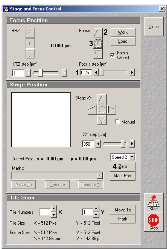
Wait 5 minutes for the focus to adjust due to temperature variations, and then refocus to the brightest FOV. Open the Stage and Focus control window (Figure 15). In the stage control window set the Z Focus step (Figure 15, 1) to 0.25 µm. Using the focusing arrows (Figure 15, 2) raise the focal plane to 0.75 µm above the brightest FOV. This is the proper height to perform ablations. The FOV should be slightly dimmer. Set this point to zero (Z: Figure 15, 3). In the stage position box select zero (Figure 15, 4). Now you will know the position of your first ablation site.
-
15.
Now that the dish has been leveled, ablation can commence once you have generated a ROI template. In essence this is the same way you would generate ROIs for FRAPing (Fluorescence Recovery After Photobleaching) a sample. To generate ROIs select the Edit ROI window (Figure 16A and C). The window allows you to generate and save hundreds of different ROIs in a single FOV as templates. To begin, in the Scan Control window select New to generate a new image window. From the bottom dialog boxes in the Edit ROI window (Figure 16A, 1 and black box) select a shape (i.e., circles, polygons rectangles, etc.). Then draw the shape onto the new image window (Figure 16B). Once drawn the shapes size and location information will appear in the Edit ROI window, checked (Figure 16C, 4). From here you can resize or reposition the shape or uncheck it and remove it. Several macros are available free from Zeiss that allow you to repeat a single ROI multiple times on the same window, which is helpful for generating a dot-based matrix, etc. It is also helpful to know the size of a single pixel with the objective and zoom you’re using. This can be found by selecting the Info button in the image window (Figure 16B, 2). The X and Y Scaling (Figure 16B, 3) can then be used for pattern spacing and sizing as well as knowing the size of the FOV, important for moving the stage horizontally or vertically when generating larger repeated patterns. Save and name the template when completed.
Figure 12.
Scan Control window with Channels panel displayed. Red box indicates an unchecked 755nm laser line.
Figure 13.
Reflected light images while trying to find the PVA thin film. A and B) Images were taken while scanning in the Z-plane. The bright linear areas indicate passing by the glass/PVA thin film (arrows). C) Once found, the field of view (FOV) should appear equally (uniformly) bright if the surface is level.
Figure 14.
Dish leveling A) Reflected light image of a dish that is slightly tilted down on the right as shown by the increase in brightness as you focus up to the glass surface. Below the image is a cartoon side view representing the glass (blue) with respect to the horizon (black line). B) Image of the confocal stage. Inset shows a magnified view (white box) of one of four adjustment screws in the stage plate. The other adjustment screws are indicated by asterisks. C) Simplified schematic of the tilted dish in panel A and how to correct the tilt by screwing in both right-side adjustment screws, until an in-focus evenly illuminated FOV is attained (right-side of arrow).
Figure 15.
Stage and Focus Control window in the Zeiss AIM software. 1 indicates the focus step set at 0.25 µm. 2 indicates toggle arrows for focus position. 3 indicates the focus zeroing button. 4 indicates the Stage position zeroing button.
Figure 16.
Edit ROI window and pattern generation. A) Edit ROI window with the shape dialog boxes (1 and black box). B) Example of generating a single circle once the circle dialog button is selected in the Edit ROI window in panel A. 2 indicates the info. button which shows on the on the left-hand side of the image window. 3 (upper left) indicates where pixel scaling information can be found. C) Edit ROI with the ROI definitions (4 and black box) for the circle shown in panel B.
Photoablation
-
16.
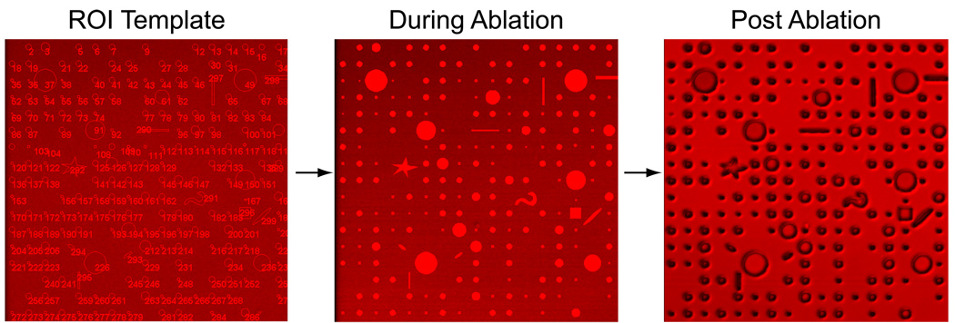
With the above steps completed, you can now proceed with photoablation. First, check that you are still focused ~ 0.75 µm above the brightest focal plane; readjust if necessary. In the Scan control window under the Channels panel check the 755 nm TP on. Select the ROI template of your choice from the Edit ROI window. In the Scan control window select the ROI button (2nd row from top 2nd from the right, see Figure 12). Select Single scan button. The ROIs in the template should be slowly scanned from top to bottom, taking around 15 seconds with the parameters set and discussed earlier. Because of the intense level of light hitting the sample the ROIs will appear saturated with light (255 on an 8-bit scale). Once the Scan has completed, uncheck the TP 755 nm line in the scan window, deselect the ROI tab, and Fast XY scan the FOV to observe the post ablation result as shown in figure 17.
-
17.
To generate multiple FOV of the same pattern use the Stage and Focus control window to move the stage over by setting the XY step to exactly one FOV (use the calibrated XY information multiplied by your scanning window size, assuming X and Y are equal). This works best for dot or separated patterns such as the example illustrated in figure 17. However, if using a linear pattern, which needs to be seamlessly continued, we recommend reducing the XY step by one or two microns to provide an appropriate overlap.
Figure 17.
From template to ablated pattern. The three images representing the ROI template (left), what is observed during the ablation (middle), and the post ablation pattern (right).
Automating µPP with macro functions
To this point you should be able to efficiently photoablate PVA thin films for a single FOV. Once the configurations have been set correctly and the ROI templates are generated, there is no true need to sit at the scope moving the stage from place to place if the process can be automated. This can be achieved through the Multitime macro in the AIM software. Originally intended for timelapse imaging, Multitime allows the user to choose multiple locations within the dish. Instead, here we use Multitime to automate the µPP process. An additional feature is the ability to “tile” around a specified point; that is to image an array of images around a single point in a tile or grid-like fashion. The next several steps will help you to achieve this automatation process. While the Multitime macro has many functions, we are only going through those that directly pertain to automating µPP.
-
18.
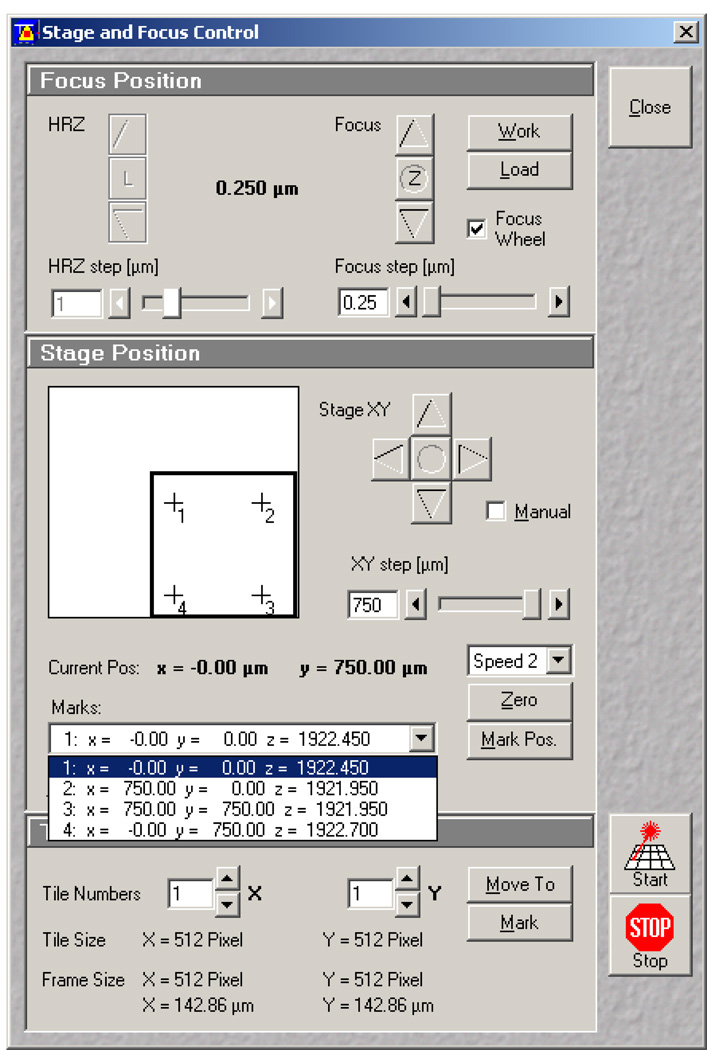
After you have found the proper Z-plane and zeroed your position as in step 14 go to the Stage and Focus control window (Figure 18). In the Stage position box (center) select Mark Pos. (Figure 18, 1). The example in Figure 18 shows how this was repeated four times 750 µm apart. Each mark is listed in the dropdown menu below. These marked positions will be used for tiling in the Multitime macro. Keep this window open since you will be referring to later. Note: It is helpful to move the stage while in Fast XY mode. Once to the correct XY position, readjust the Z-plane to be approximately 0.75 µm above the brightest FOV then mark the position, but do not zero.
-
19.
Prior to starting, create a new database (File>New File) and save it in an appropriate place.
-
20.
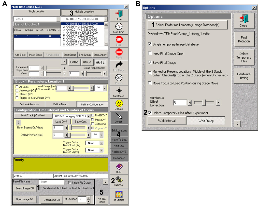
In the main AIM window, select the Macros menu. If the Multitime macro does not appear in the window, load it (if unfamiliar with Macros ask your Microscope facility director or your Zeiss representative for help with installation). Open the Multitime window. At the bottom of the window (Figure 19A, bottom, 1) select the Image DB dialog button to choose the database you generated earlier.
-
21.
From the window buttons on the right-hand side, select Options (Figure 19A, 2 and 19B). In the Option window first create a temporary image database (Figure 19B, 1). This is where the software saves your ablation images. Next, check the dialog box that says “Delete Temporary files after final experiment” (Figure 19B, 2). Close window.
-
22.
From the top of the window select Multiple locations (Figure 19A, 3), which will allow you to choose more than one point to scan. Note: steps 1–3 in Multitime only need to be performed once. After performing these actions once Multitime will remember the settings.
-
23.
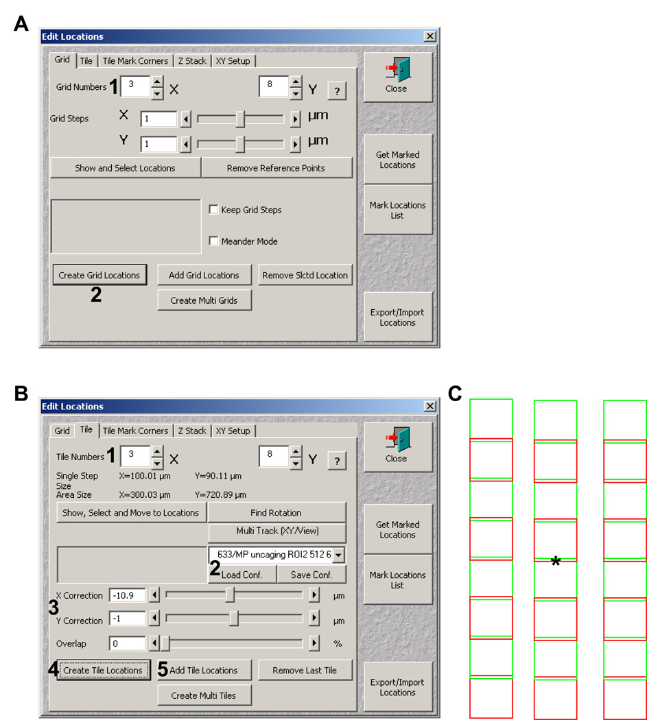
Next choose Edit location (Figure 19A, 4). The edit location window (Figure 20A) will allow you to tile around the marked positions from step 18. Under the Grid tab change the X and Y Grid numbers to the appropriate number of FOVs to tile in each plane (Figure 20A, 1), and then select Create Grid Locations (Figure 20A, 2). This generates a list of points in the Multiple locations dropdown menu.
-
24.
Next select the tile tab (figure 20B). From top to bottom 1) change the tile numbers X and Y (Figure 20B, 1), 2) select the configuration to be used from the dropdown menu, then load it by hitting Load Conf. (Figure 20B, 2), 3) Set your X and Y correction (Figure 20B, 3; used for overlapping or spacing FOVs apart).
-
25.
In the Stage and Focus control window select a position from the dropdown menu, and select Move To. Then back in the Edit Location window select Create Tile Locations (Figure 20B, 4). If more than one location is to be tiled, move to its position then select Add Tile Location (Figure 20B, 5; after your initial locations all other locations are added in this manner).
-
26.
Go to the Scan Control window and select ROI. This is very important. If not selected, the Multitime Macro will photoablate the entire FOV.
-
27.
Select the No Tile Mode (Figure 19, 5). This stops the tiling of the images collected into a larger single image. Select Start in the Multitime window. You should start seeing Multitime running. At the bottom of the Multitime window information should begin appearing telling you the position, scan number, and other information. It is helpful to time the process for a single FOV plus the stage movement to estimate your finishing time.
-
28.
Once this Multitime has finished check several FOVs to be sure the ROI template has been repeated. Close the Multitime Macro window. If more patterning is required in the same dish (the same or a different pattern) simply move to a new nonablated region being sure to know your current position with respect to all previously ablated areas. Repeat finding the Z-plane, reset zero for X, Y, and Z. The original zero point (0, 0, 0 for X, Y, and Z, respectively) should now be listed in the Stage and Focus control window as something different. For example, if you moved over 2000 µm in X, 0 µm in Y, and 1.0 µm in Z the original position should read: x= −2000.00 y=0.00 z= −1.00.
Figure 18.
Using the Stage and Focus Control window to mark multiple tiling positions. The black box indicates 4 points that were selected for tiling.
Figure 19.
Multime macro window (A) and the Options window (B). The bold numbers indicate the order each step is to be performed.
Figure 20.
Tiling with Edit Locations window. A) The Edit locations window grid tab showing the grid number dialog (1) and the create grid locations button (2) for grid generation. B) The Edit locations window tile tab with tile numbers (1), configuration (2), XY correction (3), and Create tile locations (4) highlighted. C). Schematic representation of the tiled grid generated based on the parameters shown in panel B. The asterisk represents the marked positions chosen in the Stage and Focus control window.
Basic protocol 4
Dish Quenching
Following the photoablation of the PVA thin films, the next step is quenching any unreacted aldehydes. Quenching the thin film is important for three reasons: 1) it reduces any reacted aldehydes leading to a stronger covalent attachment of the thin film to the glass surface, 2) the reduction of the aldehydes, especially if glutaraldehyde is used, decreases autofluoresence in the blue to green wavelengths (490–540), and 3) it acts to block any free radicals which may be produced in the thin film during photoablation. Because sodium borohydride is very hygroscopic, we suggest desiccating it at room temperature in small aliquots in microcentrifuge tubes. Use a single tube 4–5 times and discard the remainder. The reaction that occurs when NaBH4 comes in contact with water is temperature dependent, being more vigorous as temperature increases.
Materials
µPP patterned dishes generated in basic protocols 1–4
200 mM Ethanolamine buffer (see recipe)
Stericup™ or other solution filtering units
PBS buffer (Hyclone)
Scale
PBS with Penicillin/Streptomycin and fungizone (see recipe)
Sodium borohydride solution (see recipe)
Micro centrifuge tubes
1M NaOH solution (see recipe)
Storage containers
To each photoablated dish add 2 mls of the ethanolamine buffer after photoablation. Dishes can be kept like this at 4°C in an airtight container for up to one month. Note: The ethanolamine buffer should be added on the same day (preferably within an hour) of photoablation.
If photopatterned dishes have been stored at 4°C, allow them to warm at room temperature for five minutes.
Weigh out 40 mg of NaBH4 into a single microcentrifuge tube. Add 1 ml of 1M NaOH. Triturate several times.
To each dish add 20 µl of the NaBH4 solution mixed in step #3. Replace dish lid, swirl several times to mix, and incubate to 8 minutes at room temperature. You should start to see bubbling after 1–2 minutes which shows the reaction is occurring.
Aspirate off NaBH4 solution and rinse 2 times with PBS. Add 1–2 mls of PBS with Pen/Strep and fungizone. Store for up to 1 month.
Basic Protocol 5
Extracellular Matrix Adsorption and Cell Plating
The final step of µPP is adsorption of an ECM molecule to the photoablated patterns. Here we describe the attachment of fibronectin to photoablated dishes; however. any other ECM molecule or even growth factors can be absorbed in this fashion. Once the ECM is adsorbed to the surface, it is important to block attachment of other molecules (other ECMs, growth factors, etc.) found in serum using heat-denatured bovine serum albumin (BSA). For fluorescence microscopy techniques where the patterns are invisible, prior direct conjugation of a fluorescent dye to the ECM molecule of choice is helpful for pattern visualization. A general fluorescent dye labeling protocol for N-hydroxy succimidyl ester-based dyes can be found in the supporting protocol 2 at the chapter’s end. Pluronic F-127 is a nonionic detergent/surfactant which is used here to help with blocking nonspecific protein adsorption to nonablated surfaces.
Materials
µPP patterned dishes generated in basic protocols 1–4
Fibronectin at 2mg/ml concentration in PBS or other suitable buffer
2M NaCl solution
PBS buffer with 0.1% Pluronic F-127 (see recipe)
PBS buffer
Lyophilized BSA
Stirrer/hotplate
Scale
Flea Micro™ magnetic stir bar (VWR)
Glass test tube capable of holding 30–50ml of solution
400 ml pyrex™ beaker
Ice in an ice bucket
Digital thermometer
Heated incubator
Microcentrifuge tubes
0.5% Trypsin/EDTA solution (GIBCO)
DMEM for NIH/3T3fibroblast culture (see recipe)
Hanks Balanced Salt Solution (HBSS, GIBCO)
50 ml conical tubes
Waterbath heated to 37°C
Table top swinging bucket rotor centrifuge with adapters for 50 ml conical tubes
Vacuum aspirator
Inverted microscope equipped with a 10X phase contrast objective.
Tissue culture hood
NIH/3T3 cells grown to 60–70% confluency in a 100 mm diameter dish in 10% CO2 incubator
-
1.
Calculate the total amount fibronectin solution needed for all dishes. Because the glass surface only needs to be covered we use ~ 100µl per dish. Next calculate the volume of fibronectin (at 2mg/ml) needed to attain the proper concentration. For example, for 4 dishes, add 2 µl of 2mg/ml fibronectin to a microcentrifuge tube followed by 398 µl of PBS with 0.1% pluronic F-127 buffer for a 10 µg/ml solution. Pre-warm concentrated fibronectin solution to ~37°C prior to mixing the solution. Note: fibronectin is an active molecule which over time will lose activity when left at 4°C for extended periods. We suggest keeping small aliquots (~ 20µl) frozen at −80°C and defrosting and using for only one week stored at 4°C. Once diluted, the fibronectin solution must be used promptly and cannot be stored.
-
2.
In a tissue culture hood add 100 µl of the 10 µg/ml fibronectin to each dish, cover and incubate for one hour at 37°C.
-
3.
While waiting, heat 250 ml of water in a 400ml beaker on the stirrer/hotplate to ~85°C. Weigh out 0.3 grams of BSA in a 50ml conical tube. Bring volume/weight up to 30 grams with PBS buffer. Incubate in a 37°C waterbath until BSA goes into solution, around 15 minutes. Note: this heat-denatured BSA solution should be made fresh and can be used for a maximum of only 1 day.
-
4.
Once in the BSA has gone into solution, transfer the 1% BSA solution to the glass test tube and add the stir bar. Next place the test tube in the ~85°C water. Turn on the stirplate to medium.
-
5.
Directly measure the temperature of the 1% BSA solution with the digital thermometer. Set a timer for 3 minutes. Wait until the solutions temperature reads 83°C then start timer. Monitor the temperature over the next three minutes. If the solutions temperature goes above 85°C, remove the test tube from the water bath and cool briefly, keeping the temperature a minimum of 83°C. After 3 minutes time remove 1% BSA solution from water and cool in an ice bath until solutions temperature is below 37°C.
-
6.
After the one hour incubation of the fibronectin on the µPP dishes, Bring back to the tissue culture hood, aspirate fibronectin, and rinse 3 times with PBS.
-
7.
Add 2 mls of 2M NaCl solution and incubate 5 minutes at room temperature to reduce nonspecific protein binding. Aspirate NaCl solution, and rinse 3 times with PBS.
-
8.
Add 2 mls of heat-denatured 1% BSA solution to each µPP dish and again incubate for one hour at 37°C.
-
9.
Rinse dishes 3 times with PBS, and store in an airtight container in 2 mls of PBS plus Pen/Strep and fungizone until use. Use within 3 days of this last step.
Attachment of NIH/3T3 fibroblasts to µPP patterns
-
10.
Detach NIH/3T3 fibroblasts from tissue culture dish by rinsing twice with 6ml of HBSS. Add 5ml of the trysin/EDTA solution and wait 30–60 seconds. Aspirate off excess and incubate for 2–3 minutes at 37°C. All solutions should be pre-warmed to 37°C.
-
11.
Add 10 ml NIH/3T3 fibroblast medium to the dish, triturate and transfer to a 50 ml conical tube. Spin cells down in the swinging-bucket centrifuge for 4 minutes at 1,000 rpm.
-
12.
After centrifugation aspirate off excess medium leaving the cell pellet undisturbed. Tap tube firmly on tissue culture hood working area. Add 10 ml of medium to tube and triturate several times to loosen cell clumps.
-
13.
Add 1–2 mls of cells to each µPP dish. Incubate for 10–15 minutes and then check cell attachment to patterns using a 10X phase contrast objective on an inverted microscope. When cell begin to attach they should appear phase dense when compared to non-adherent cells. If the proper amount of cells is not attached check dishes every five minutes.
-
14.
When the proper amount of cells has attached, gently aspirate the excess and add 1.5–2 mls of fresh medium. Incubate for a further 30 minutes before imaging.
Supporting protocol 1
Setting the confocal scan heads rotation offset
As mentioned earlier in basic protocol 3, the X and Y galvanometric scan head mirrors can be slightly misaligned or offset from a true horizontal or vertical plane. This becomes an issue when using the Multitime Macro for tiling: improper scanner alignment will result in pattern being askew from FOV to FOV. For example, if generating a lined pattern which is meant to be continuous, lines may be offset. The following protocol alleviates this rotation alignment issue. This can be done simply in one of two ways: First, is to use a grid slide supplied by Zeiss for the alignment, and second is to generate a grid of your own using µPP. Both require the same steps. Any differences between the protocols are discussed.
Materials
PVA thin film-coated MatTek dishes generated in protocol #2 (option #1)
Grid slide, Objektträger (option #2, cat# 474028, Zeiss)
Zeiss 510 LSM NLO confocal microscope or later model with 1.5W minimum tunable two-photon titanium:Sapphire laser, and a 633nm HeNe2 laser (5mW power output), and a 543nm HeNe1 laser (1mW power output)
Fluorescent highlighter, any color (option #2)
Kimwipes ™
For option 1
Turn on the microscope, the AIM software, and the appropriate lasers for performing µPP. Load your µPP configuration. Place a PVA thin film-coated dish on the stage and follow the pre ablation setup in basic protocol #2, steps 10 through 14 in order to find the proper Z-plane for µPP.
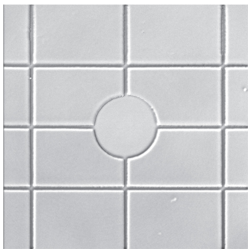
Create a new ROI template in a pattern similar to figure 21. The grid and circle pattern helps to determine the rotational offset. The spacing of the grid is not important, just that horizontal and vertical lines as well as curved lines are incorporated into the pattern.
Being sure to have your zoom set for 1X, photoablate the pattern in the PVA thin film. Save the configuration with the TP 755nm line unchecked. In the Focus and Stage control window, mark the position.
Figure 21.
Microphotopatterned grid used for rotational alignment of the XY galvanometric scanning mirrors in the confocal head with the stage.
For option 2
-
1.
Turn on the arc lamp followed by the microscope, the AIM software and the 543 nm HeNe1 laser on. Select a configuration to image Cy3, Alexa Fluor 543, or Rhodamine dyes (If needed, ask your microscope facility manager for help).
-
2.
On the grid slide, locate the grid in the center. Mark the grid with the fluorescent highlighter. Gently wipe off excess with a Kimwipe. Add a drop of oil over the grid and position the slide properly in the stage holder. Use epifluorescence to find the grid using a 63X 1.4 NA objective.
-
3.
Once found, switch to LSM mode, adjust the Z-plane while in Fast XY. Adjust the settings (PMT gain, laser output, etc.) and save as a new configuration. Scan the grid pattern until you find a region which contains both the vertical and horizontal lines as well as part of a curved arc (the grid pattern usually has a small and large circle pattern). In the Focus and Stage control window, mark the position.
The following steps are the same for option 1 and 2
-
4.
Open the Macros menu and select the Multime Macro. Open the Edit Locations window and select the tile tab (Macros>Multime>Edit Locations> Tile tab).
-
5.
Select the configuration you saved in step 3 for either option and select load Config..
-
6.
Select the Find Rotation button. A new window should appear similar to figure 22.
-
7.
Choose Calibrate (Figure 22, 1). This should take ~20 seconds before a number should appear in the Rotation [°] dialog on the left which represents the rotational offset (Figure 22,2). Go to the Zoom, Rotation and Offset box in the Mode panel of the Scan control window. Use the number found in the Rotation [°] dialog for your rotational offset in your µPP configurations. Save the configurations once complete.
Figure 22.
Tile Scan Rotation dialog window in the AIM software.
Supporting protocol 2
Direct Fluorescent Labeling of Fibronectin
For any type of micropatterning including µPP it is important to know whether the ECM is being adsorbed to the patterns and not nonspecifically. While antibodies can help with this determination, the direct approach is often best, especially when conducting live-cell fluorescence imaging. Below we detail one method of directly-labeling fibronectin with N-hydroxy succimidyl (NHS) ester based fluorescent dyes. Before proceding several items should be noted: 1) NHS ester reactions are pH and temperature dependent, 2) they are hygroscopic and once in contact with aqueous solutions begin reacting immediately, and 3) the ratio of protein to dye is important, with your reaction time being based on this and the parameter is 1 above. For every 1 mg of protein, 5 to 10 µg of dye should be used (200:1 or 100:1 ratio). This is slightly below a 10-molar excess normally suggested for dye-to-protein conjugations. Over-labeling ECM proteins can negatively affect cell attachment and/or migration. If using different starting protein amounts, recalculate the amount of dye to match these ratios. More information about these other types of fluorescent conjugations can be found in “Bioconjugate Techniques” by Greg Hermanson (Hermanson, 2005).
Materials
500–1000 µl of Fibronectin at 2mg/ml concentration or 2 mg or lyophilized
100mM Borate Buffer pH 9.0 (see recipe)
NHS-ester based fluorescent dye of choice (several are available from Invitrogen and Pierce)
Dimethylsulfoxide (DMSO)
Microcentrifuge tubes (1.5 ml size)
Desalting Spin column or dye-removal columns capable of ~1 ml volumes (Pierce)
End-over-end rotating mixer, e.g., Labquake™ rotating mixer (sometimes termed a "Rotisserie Shaker")
Slide-A-Lyzer (Pierce)
Aluminum foil
Cooled centrifuge capable of 10,000 rpm with 15ml conical tube holders
NHS-ester based fluorescent dyes are hygroscopic and should be kept in DMSO until use. Dilute the lyophilized dye with DMSO to a concentration of 1mg/ml. Split into aliquots of ~25 µl. Store at −20°C until use.
If starting from lyophilized fibronectin add 1 ml of 100mM borate buffer (pH 9.0) to make a 2 mg/ml concentration. If starting from fibronectin in PBS or other buffers (~pH 7.4), dialyze in borate buffer (See chapter XXXX for details on dialysis).
Warm 2 mg/ml fibronectin to room temperature prior to reacting with NHS ester dyes. Defrost NHS-ester dye (1mg/ml concentration) prior to opening tube since it will absorb moisture from the air.
Add 1ml of fibronectin (2mg/ml, in Borate buffer) to a micro centrifuge tube. Add to the fibronectin solution 10 to 20 µl of the concentrated dye (1 mg/ml). Close tube and wrap with aluminum foil.
Incubate at room temperature for 1 hour on an end-over-end mixer at approximately 8 rpm. For other ECM molecules it is recommended that the reaction be incubated at 4°C for 2 hours.
After 1 hour, remove unreacted dye using either a desalt spin column or dye removal column and follow the manufacturer's protocol. Alternatively, gel filtration or dialysis of the unreacted dye can be performed.
Supporting protocol 3
Using multiple ECM proteins with µPP
One advantage of µPP over other patterning techniques is the ability to repeat the process after an initial photoablation, quenching, ECM adsorption, and blocking. This allows placement of different ECMs within microns of each other at the subcellular levels (Figure 23). It is crucial here to use 0.1% pluronic F-127 for protein dilution as well as for rinsing steps to deter nonspecific protein adsorption. The following protocol details the process.
Figure 23.
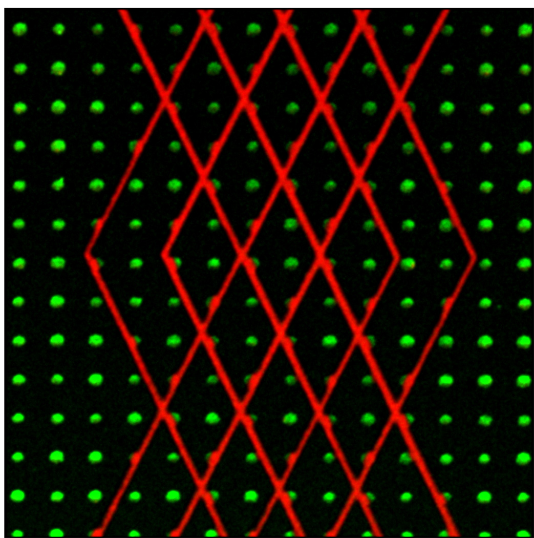
Dual ECM patterns by performing µPP twice in series. A first ablation was performed followed by quenching, ECM adsorption, and blocking. A second round of ablation was done is the presence of the second ECM. Green dots are fibrinogen and red lines are vitronectin. Dots are spaced 5 microns apart.
Materials
PVA thin film-coated MatTek dishes generated in protocol #2
PBS buffer with 0.1% Pluronic F-127 (see recipe)
1% heat-denatured BSA solution (make fresh and keep < 1 day)
Permanent marker
2 different, fluorescently-labeled ECM molecules/growth factors at the proper final concentration (user defined)
Prior to photoablation (basic protocol #3) mark a single side a PVA thin film-coated dish along the edge of the attached coverslip. Align the marked edge with the front of the microscope stage. Proceed with rest of the photoablation procedure. This part can be automated. Continue with the full process through basic protocol #5, substituting a fluorescently-labeled protein during the adsorption step (#2 of basic protocol #5). We suggest that this first labeled protein have a fluorophore in the visible range of emission, between 510 and 610 nm. Far red dyes such as Cy5, Alexa Fluor 633 and 647, or Dylight 649 are not recommended for this first stage.
After blocking the fluorescently-labeled protein with 1% heat denatured BSA, a second photoablation can be done. Here there are several options which may depend on the first adsorbed protein: 1) the surface of the film can be dried using compressed air immediately before photoablation, 2) the surface can be left in PBS, or 3) the second fluorescently-labeled protein can be added to the surface. The photoablation process can still occur in solution (options 2 and 3), however due to the presence of water, its efficiency can be reduced.
Align the marked side of the photoablated dish with the front of the stage. Use epifluorescence to scan the area(s) of the dish for the first photoablation site. Once found, realign the dish to the best of your ability by hand. Fast XY scan the FOV using the most suitable configuration for the fluorophore used. While scanning make the fine alignment adjustments using the rotation dialog box in the Mode panel of the Scan control window. To help with this open the Edit ROI window and choose the ROI template that was used to generate the first pattern (step 1 above). Leave the Edit ROI window open without selecting the ROI tab in the Scan control window, and continue scanning. This keeps the ROI template visible while scanning a full FOV. Manually or using the Stage and Focus control window, align the ROI template over the fluorescent patterns. If using the same pattern, offset the template from the original position in either X or Y planes, or both. The amount of offset will depend on the the original ROI.
Load the µPP photoablation configuration into the AIM software. Photoablate single FOVs at a time. We recommend this step not be automated.
Once finished, follow steps 6 through 8 in basic protocol #5, substituting PBS with 0.1% pluronic F-127 for PBS. Blocking the surface with 1% heat denatured BSA should follow each protein added to the photoablated dish to prevent non-specific protein attachment. Quenching with sodium borohydride is only required after the initial photoablation. Requenching will reduce fluorophore fluorescence and is not recommended.
Repeat the process (steps 2 through 5) if needed. Plate cells on the surface as in steps 10 through 14 of basic protocol #5.
REAGENTS AND SOLUTIONS
Sodium phosphate buffer, 100mM (pH 8.0)
6.90g Sodium Phosphate Monobasic (NaH2PO4)
dH2O to 400 ml
add several solid NaOH pellets at a time while mixing until pH is ~8.0
dH2O to 500 ml
Sterile filter (0.2 µm pore-size filter) and store for up to 6 months at room temperature
Ethanolamine buffer, 200mM
4.88 g ethanolamine hydrochloride (EtOHNH3, crystalline form, 99%, Sigma)
Sodium phosphate buffer to 250 ml
Sterile filter (0.2 µm filter) and store for up to 6 months at room temperature
PBS with penicillin/streptomycin and fungizone
490 ml DPBS/modified containing calcium and magnesium (Hyclone)
5 ml Amphotericin B (250 µg/ml) (Gibco)
5ml Pencillin/Streptomcyin (10,0000 unit/µg per ml each, respectively) (Gibco)
Mix and store for 6 months at 4°C
PBS with 0.1% pluronic F-127
199 ml of PBS (Hylcone)
1ml of 20% pluronic F-127 in DMSO (Invitrogen)
Mix well on a stirplate (warming to ~37°C will help this process)
Sterile filter and store for up to 2 months at room temperature
Borate buffer, 100mM (pH 9.0)
3.092 g boric acid (powder 99.5%, Sigma)
dH2O to 400 ml
add several solid NaOH pellets at a time while mixing until pH is ~9.0
dH2O to 500 ml
Sterile filter and store for up to 6 months at room temperature
Sodium borohydride solution
40 mg Sodium borohydride (NaBH4, hygroscopic powder, Sigma)
1 ml NaOH
Mix well
Make up fresh each time
DMEM for NIH/3T3 fibroblast culture
440 ml Dulbecco’s Modified Eagle’s Medium (DMEM/High Glucose Modified, Hyclone)
5ml Pencillin/Streptomcyin (10,0000 unit/µg per ml each, respectively) (GIBCO)
50 ml Bovine calf serum (BCS) (Hyclone)
Sterile filter and store for up to 1 month at 4°C
Sodium Hydroxide, 1M
20g NaOH pellets
dH2O to 500 ml
Mix well
Sterile filter and store for up to 6 months at room temperature
Sodium Hydroxide solution, 200mM
50 ml of 1M NaOH solution
200 ml of dH2O
Mix well
Sterile filter and store for up to 6 months at room temperature
COMMENTARY
Background Information
Micropatterning using Self-assembled Monolayers
Micropatterning of ECM molecules originated by using self-assembled monolayers (SAMs) of alkanethiolates attached to gold-coated surfaces (Singhvi et al., 1994; Mrksich et al., 1995). The alkanethiol molecules consist of a sulfhydryl end terminal, a middle spacer which is normally an ethylene-glycol backbone, and a head group that differs from the end terminal. Sulfhydryls or thiols have a high affinity for electron-dense gold and they bind, leaving the head groups pointing upward away from the gold surface. By changing the head group of the alkanethiol to a hydrophobic methyl (CH3) or a hydrophilic hydroxyl (OH) group, the surface chemistry is altered which will promote or deter ECM protein adsorption, respectively. Traditionally, in order to physically isolate hydrophobic from hydrophilic regions on a 2D surface, a “rubber stamp” is generated that can physically ink the hydrophobic alkanethiol onto a gold surface. The remaining regions are backfilled with a hydrophilic alkanethiol and finally an ECM protein can be added which will only attach to the patterned hydrophobic regions of the surface. This process, known as microcontact printing (µCP), relies mostly on nanolithography techniques to generate a silicon “master” mold from which the polydemetylsiloxyane (PDMS) stamp is created.
Poly(vinyl) Alcohol Properties
As alluded to earlier, PVA is a highly hydrophilic polymer. It consists of a carbon backbone and hydroxyl groups located on every other carbon. PVA comes in varying molecular weights (MW), from as low as 6,000 to greater than 100,000 daltons. PVA is generated from the hydrolysis of poly(vinyl) acetate. The percent hydrolysis that is listed with most PVA’s defines the total amount of poly(vinyl) acetate hydrolyzed to PVA. The percent hydrolyzed should be as high as possible and is related to its hydrophilicity, with 98–99% being ideal for this application. With regards to the MW: the larger the PVA monomer, the thicker the thin film becomes. We have found that using any of the MWs between 13,000 and 100,000 in a 5% solution can be used for µPP. Interestingly, after ablation of a high MW PVA film, the patterns remain visible via phase contrast and DIC imaging after submersion in buffer. This is not the case with 13,000 MW PVA, although labeling with fluorescent EMC proteins confirms proper local ablation (A.D.D., unpublished findings). Because of this, low MW PVA thin films are generally better for higher resolution fluorescence microscopy, and high MW PVA is helpful for visualizing the ECM patterns at lower magnifications.
Photoablation with two-photon microscopy
The process of photoablation is based on the ability of the PVA polymer to absorb light in the ultraviolet (UV) range (100–380nm) (matsumoto et al., 1958). Other large polymers that have the ability to form a hydrogel such as polyacrylamide and polyethylene glycol can undergo photolytic degradation (Yamato et al., 2003, Chen et al., 2003). Two-photon femto-second pulse lasers mimic UV wavelengths using 720–760nm light, and can excite UV-based fluorophores such as DAPI, coumarin, and Hoechst. For more information on properties and process of two-photon excitation and confocal microscopy we suggest reviewing units 4.5 and 4.11 on confocal and two-photon excitation microscopy, respectively. Absorption of UV light can initially result in polymerization of many polymer solutions (Du 2007). However, continued exposure can disrupt primary bonds; in PVA’s case the –OH to the carbon backbone. Further exposure results in a breakdown of the carbon backbone itself. With µPP we use this property of PVA to locally a breakdown or ablate the thin film, exposing the underlying glass to which ECM proteins can later be adsorbed.
Critical Parameters and Troubleshooting
The key elements during the multi-step µPP process requiring consideration are: 1) the PVA conjugation the glass surface, 2) how the PVA thin film is kept and 3) several parameters associated with the two-photon laser for proper photoablation. Many other troubleshooting tips are found throughout the text, where they are directly pertinent to the protocols. Improper cleaning and/or activation of the glass surface can result in thin film detachment. Checking dishes for debris during each phase of the processing is important and should not be overlooked.
The PVA thin films need to be hydrated. PVA hydrogels can undergo crystallization when dehydrated (Peppas et al., 1977). While this process greatly increases their tensile strength, it greatly reduces their hydrophilicity from removal of hydroxyl groups and hence PVA’s ability to deter protein adsorption and cell attachment is compromised. This will have no effect on the photoablation process, however. Critical times where dehydration can greatly affect the thin film are initially after spincoating, when the macromolecular monolayer may still be reacting with the activated glass surface. Short-term exposure to dry conditions such as during the photoablation on the microscope is tolerated.
Many issues stem from proper maintenance of the two-photon laser. We found that the amount of fluorescently-labeled fibronectin attached to a given area is highly dependent on the total amount of light energy reaching the PVA thin film (Doyle et al., 2009). Small alignment issues of the two-photon source with the confocal scan head will greatly reduce the light throughput to your sample and can result in improper photoablation within the whole field of view or just a part of it. If the two-photon system is heavily used by multiple users, more frequent mirror alignments should be performed. Other issues with uneven photoablation can arise from focus drift issues, bubbles in the immersion oil, and an uneven FOV. Another issue to factor into proper photoablation is the tuning of the TP laser. Technically speaking, the two-photon absorption of a given wavelength should be same between different two-photon sources. However, there can be variation in the best or most suitable wavelength to maximize wavelength absorption. As it is recommended by most experts, you should test several wavelengths until the best one is found for your particular two-photon source to illuminate, or in this case photoablate, your sample. Starting with 755 nm, tune the Ti:Sapphire laser up or down ten nanometers at a time. Photoablate a simple pattern such as a field of same-sized dots at the particular wavelength, then document the time taken and whether the ablation was efficient (complete removal of the PVA thin film) or not (only partial removal). Partial photoablation of patterns, where the PVA thin film is not completely removed from the glass surface, can lead to an inability of ECM protein adsorption and hence can affect cell attachment and/or migration.
Anticipated Results
It is expected that after generating the PVA thin film dishes and creation of the configurations and ROI templates, you should able to generate micropatterns to which ECM or other proteins can readily adsorb. Once patterns have been produced you should find that cells should readily attach to patterns, especially linear structures, (lines and lanes). There should be limited autofluorescence from the dish surface and all fluorescence microscopy techniques, from TIRF to spinning-disk confocal and two-photon confocal microscopy, should be effortlessly performed.
Time Considerations
As described in the strategic planning section, the many different parts of µPP can be performed not only on separate days but weeks if not months apart between glass activation (basic protocol #1) and ECM adsorption/cell attachment (basic protocol #5). It is best to plan accordingly. For example, activating 30 dishes or more depending on your usage should be enough for 4 weeks. However, it is not prudent to continue all 3 dishes through the thin film deposition stage (basic protocol #2) unless you can process 30 dishes in a single week. Furthermore, how many of 30 dishes can be used in a 1–3 day period after ECM adsorption needs also to be considered. Pre-planning for dish need and usage will decrease your issues at key steps. One important time consideration is between formation of the PVA thin film through spincoating and the addition of the ethanolamine buffer after photoablation. Although as rare as this would occur, a short time (under 2 hours) between these two steps could cause release of the thin film from the glass surface due to a lack of covalent attachment.
Literature Cited
- Chen S, Kancharla VV, Lu Y. Laser-based microscale patterning of biodegradable polymers for biomedical applications. Int. J. of Material & Product Technology. 2003;18(4/5/6):457–468. [Google Scholar]
- Doyle AD, Wang FW, Matsumoto K, Yamada KM. One-dimensional topography underlies three-dimensional fibrillar cell migration. J. Cell. Biol. 2009;184:481–490. doi: 10.1083/jcb.200810041. [DOI] [PMC free article] [PubMed] [Google Scholar]
- Hermanson GT. Bioconjugate Techniques. 1st ed. San Diego, CA: Academic Press; 1996. [Google Scholar]
- Lehnert D, Wehrle-Haller B, David C, Weiland U, Ballestrem C, Imhof B, Bastmeyer M. Cell behaviour on micropatterned substrata: limits of extracellular matrix geometry for spreading and adhesion. J. Cell Sci. 2004;117:41–52. doi: 10.1242/jcs.00836. [DOI] [PubMed] [Google Scholar]
- Matsumoto M, Imai K, Kazusa Y. Ultraviolet spectra of Polyvinyl Alcohol. J of Poly. Sci. 1958;28(117):426–428. [Google Scholar]
- Mrksich M, Chen CS, Xia Y, Dike LE, Ingber DE, Whitesides GM. Controlling cell attachment on contoured surfaces with self-assembled monolayers of alkanethiolates on gold. Proc Natl Acad Sci U S A. 1996;93(20):10775–10778. doi: 10.1073/pnas.93.20.10775. [DOI] [PMC free article] [PubMed] [Google Scholar]
- Mrksich M, Whitesides GM. Using self-assembled monolayers to understand the interactions of man-made surfaces with proteins and cells. Annu Rev Biophys Biomol Struct. 1996;25:55–78. doi: 10.1146/annurev.bb.25.060196.000415. [DOI] [PubMed] [Google Scholar]
- Peppas NA, Merrill EW. Development of semicrystalline poly(vinyl alcohol) hydrogels for biomedical applications. J. Biomed. Mater. Res. 1977;11(3):423–434. doi: 10.1002/jbm.820110309. [DOI] [PubMed] [Google Scholar]
- Yamato M, Konno C, Koike S, Isoi Y, Shimizu T, Kikuchi A, Makino K, Okano T. Nanofabrication for micropatterned cell arrays by combining electron beam-irradiated polymer grafting and localized laser ablation. J Biomed Mater Res A. 2003;67(4):1065–1075. doi: 10.1002/jbm.a.10078. [DOI] [PubMed] [Google Scholar]


