Abstract
Skeletonization promises to become a powerful tool for compact shape description, path planning, and other applications. However, current techniques can seldom efficiently process real, complicated 3D data sets, such as MRI and CT data of human organs. In this paper, we present an efficient voxel-coding based algorithm for Skeletonization of 3D voxelized objects. The skeletons are interpreted as connected centerlines. consisting of sequences of medial points of consecutive clusters. These centerlines are initially extracted as paths of voxels, followed by medial point replacement, refinement, smoothness, and connection operations. The voxel-coding techniques have been proposed for each of these operations in a uniform and systematic fashion. In addition to preserving basic connectivity and centeredness, the algorithm is characterized by straightforward computation, no sensitivity to object boundary complexity, explicit extraction of ready-to-parameterize and branch-controlled skeletons, and efficient object hole detection. These issues are rarely discussed in traditional methods. A range of 3D medical MRI and CT data sets were used for testing the algorithm, demonstrating its utility.
Index Terms: 3D skeleton and centerline, medial axis, volume subdivision, region growing, hole detection, distance transformation, voxel-coding
1 Introduction
Modern techniques enable the generation of large 3D volume data sets with high resolution, such as MRI and CT data sets. Skeletonization of such a volume, theoretically, promises a compact description of discrete objects, providing an efficient method for visualization and analysis, such as feature extraction [27], feature tracking [6], surface generation [9], or automatic navigation [5], [7]. Although there have been numerous studies on this technique in computer vision and pattern recognition [3], [4], most research [16], [19] focuses on 2D images, incompatible with easy 3D extension. On the other hand, 3D techniques for Skeletonization either only investigate simple or experimental data [11], [12] or resort to specific postprocessing when applied to real 3D data [13].
In this paper, we propose a simple, fast, and efficient Skeletonization algorithm, which employs voxel-coding techniques and directly focuses on real 3D volume data. Our algorithm survives the challenge of a variety of MRI and CT data sets, characterized by the following features:
Connectivity preservation: The voxel-coding algorithm itself determines the preservation, without the need to prove it. This is different from traditional connectivity-preserved distance transforms and thinning methods where considerable attention must be paid to the proof of connectivity criteria.
Centeredness satisfaction: Skeletons are initially extracted as connected voxel paths passing through sequences of clusters, then, on the basis of a minimum distance field, path points are replaced by medial points within their associated clusters.
Straightforward computation: For large, complicated data sets, computation time is critical. On the basis of our voxel-coding techniques, objects are represented as a collection of clusters instead of voxels, reducing the number of operational elements. No complicated mathematical computation is required except for the voxel coding. The algorithm only visits voxels several times and only simple value assignments are involved for each visit.
No sensitivity to object boundary complexity: The algorithm extracts skeletons based on a global voxel-coding and retrieval operation, rather than using a local template. Specifically, skeletal points are evaluated as the medial points in clusters. In contrast, almost all current skeleton methods are sensitive to noise and boundary complexity due to the use of local, template-based strategies and, usually, preprocessing is needed to reduce noise [19].
Smooth, fine, easy-to-control skeleton generation: Extracted skeletons are natural one-voxel-wide smooth curves, rather than unordered discrete voxels, ready to be parameterized for further processing. Each skeleton segment is associated with a length parameter, providing control of smooth skeletons and pruning of spurious branches. In contrast, the traditional presentation of resulting skeletons is in discrete voxel form, which is often not appropriate for further analysis and modeling.
Efficient object hole detection: Object holes are detected simultaneously with initial skeleton extraction without additional computational cost.
A strict definition of a skeleton is surprisingly difficult, but both Features 1 and 2 are the primary requirements. Features 3 through 6 are characteristic, but there is little literature discussing these properties.
Related approaches to Skeletonization are discussed in the next section. After introducing basic voxel-coding techniques in Section 3, we discuss how these techniques can be applied to extract skeletons directly from complicated volumetric objects in Section 4, including BS-coding, SS-coding and the cluster graph (Section 4.1), a skeleton extraction procedure (Section 4.2), and skeleton refinement, smoothness, and connection operations (Section 4.3). Then, we briefly analyze the algorithm, features in Section 5, followed by a description of the applications and test results in Section 6. Finally, we conclude by empirically evaluating the algorithm with regard to its use in practical applications.
2 Previous Work
There are a large variety of methods proposed for skeleton extraction in the literature. Most are divided into two classes: boundary peeling (also called thinning, erosion, etc.) and distance coding (distance transform). The basic idea of the former [10], [11] is to iteratively peel off the boundary layer-by-layer, identifying “simple points,” where removal does not affect the topology of the object [12]. This is a repetitive, time-intensive process of testing and deletion and considerable attention must be paid to skeletal connectivity since identifying simple points is not trivial—each voxel must be tested. Usually, It is difficult to prove that a 3D thinning algorithm preserves connectivity. Recently, Mao and Sonka [13] proposed a fully parallel, connectivity-preserving 3D thinning algorithm, with promising results. However, postprocessing was necessary since their algorithm failed to generate a smooth single-voxel-wide skeleton.
In contrast, distance coding methods [15], [16] try to directly extract skeletal points by testing the points’ local neighborhood based on a distance transform, which is an approximation of the Euclidean distance. The ideal distance coding-based method has three steps: 1) Approximate the minimum distance field, 2) detect all local maxima in terms of distance value, and 3) reconnect the local maxima to generate skeletons. Theoretically, the Euclidean distance provides enough information indicating whether a point is centered; the calculation of real Euclidean distance, however, is neither efficient nor algorithmically trivial, especially for large, high resolution 3D volume data sets that include complicated objects. There are many discrete simulation methods, e.g., the distance transform metric, represented in computer vision [17], [15]. Intuitively, the medial surfaces/axes can be defined as the locus of maximal disks (2D) [4], [1] or balls (3D) [7]. This leads to a skeleton consisting of more or less sparsely distributed points.
The main problem involved in transform-based methods is connectivity. Niblack et al. [16] provide a good 2D solution to this problem. In order to connect local maxima using uphill climbing rules, they added saddle points, which are local minima along a skeleton, to the skeletal point set. As Gagvani [7] noted, direct extension of this algorithm to 3D is difficult because there are not necessarily unique sequences of voxels around a given voxel. Helman and Hesselink [8] detected saddle points in a 2D vector field by computing the eigenvalues of the Jacobian matrix of the field. The accuracy of saddle points depends on the accuracy of the vector field generated from a distance transform. Three-dimensional, noisy, complex data would have too many voxels taken as saddle points, resulting in either erroneous skeleton parts or very thick skeletons.
A variant of distance coding-based methods is to simulate the “grass fire” transform using an active contour model [19]. The grass fire transform is a two-phase technique: initial fire front generation and fire front propagation toward the medial axes. The initial fire front is taken as the object boundary, while the propagation is implemented in an iterative fashion. The extension of this 2D method to 3D and its application with complicated data is challenging both in generating boundary surfaces and in performing propagation on the surfaces. Numerous branches and holes will be difficult to accommodate.
Voronoi methods [21], [22] based on triangular Voronoi diagrams, theoretically, guarantee connected skeletons, which are best suited for polygonally defined objects [23], [24]. However, many objects tend to have noisy boundaries, causing the Voronoi Diagram to be very dense and requiring considerable pruning to generate the medial axes.
To date, almost all the skeletonization techniques are locally template-based, which results in sensitivity to boundary details and noise. Preprocessing is needed to distinguish large artifacts from the salient features. The shapes of natural objects, specifically 3D objects, such as human organs, are often characterized by a rather complex or irregular outline; consequently, current methods cannot be applied or their results include too many spurious branches. Resulting skeletons are very thick in discrete point form, providing useful shape descriptions. However, they are difficult to process further.
We have completed a study on skeleton extraction for medical applications [26]. This is a fast, template-based skeleton and centerline extraction method. Recently, we developed a voxel-coding based algorithm for the extraction of cerebral sulcal curves—skeletons of deep valley-like regions between two juxtaposed cortical folds [27]. The algorithm employs two minimum distance fields: exterior boundary-based and interior boundary-based. On the basis of the first distance field, the initial skeletons are extracted by recursively retrieving adjacent points with the smallest coding value starting from local maxima points. Employing the second distance field, the algorithm deforms the initial skeleton toward the medial axis. The sulcal curves preserve topology and connectivity. It is a 2D application-oriented voxel-coding method.
In this paper, we introduce a general 3D voxel-coding-based skeleton algorithm. The techniques applied here are an extension of those in [27]. Our algorithm employs two distinct coding operations: boundary-seeded (BS) voxel coding and single point seeded (SS) voxel coding. The BS-coding generates a traditional minimum distance field (BS-field) in the volumetric object, while SS-coding generates another similar minimum distance field (SS-field) corresponding to a single seed point rather than the object boundaries. The SS-field classifies the object into a collection of clusters. Each cluster consists of connected voxels with the same code. The object skeleton is interpreted as a collection of connected paths. The paths are extracted using the methods similar to [27] for initial contour extraction or to [26] for centerline generation. The skeletal points are obtained by replacing path points by the medial points (relative to the BS-field) in the associated clusters which the paths pass through.
Our SS-coding selects only one voxel as a seed, and the voxel code generated records propagation order; the voxel retrieval is actually an extraction of initial skeletons, which follows the mechanism of medial surface/axis generation [4], [1]. A cluster is used for medial point evaluation instead of balls [7]. Our algorithm provides a continuous, ordered, and not over-covered sequence of clusters, thus generating smooth, fine, connected skeletons. The centeredness of the skeleton is guaranteed by employing a traditional minimum distance field. However, we do not require calculation of a minimum energy function as in [19], where a potential field for the energy equation was first generated, followed by an iterative simulation.
Most contemporary approaches to skeletonization fail to achieve at least one of the features listed earlier. The voxel-coding algorithm described here successfully achieves all goals listed above, providing a robust skeletonization tool for real, complicated 3D voxelized objects.
3 Basic Concepts and Voxel-Coding Techniques
Voxel-coding plays a critical role in our skeleton extraction. It is responsible for skeleton extraction, refinement, smoothness, and connection operations. Therefore, in this section, we first introduce concepts and basic voxel-coding techniques, including a shortest path extraction method.
3.1 Preliminaries
We work with 3D binary volume data sets, uniformly sampled in all three dimensions (in some applications, preprocessing is needed to resample the volume to achieve isotropy). A voxel is the smallest unit cube in the volume, with its eight vertices taking values of zero or one. A voxel is regarded as an inside voxel if all its vertices take a value of one; as an outside voxel or background voxel if all its vertices take a value of zero; otherwise, it is considered a boundary voxel. Both boundary voxels and inside voxels are called object voxels. Following the same notations in [26], [28], [29], for a voxel p, an adjacent voxel q is called a F-neighbor, E-neighbor, or V-neighbor of p if it shares a face, an edge or a vertex, respectively, with voxel p. Voxels p and q are also called F-connected, E-connected, or V-connected, corresponding to traditional 6-connected, 18-connected, or 26-connected, respectively. Two voxels are adjacent or neighbors of each other if they are at least V-connected. A voxel path is defined as a sequence of voxels satisfying the condition that adjacent voxels are at least V-connected and every other pair of voxels are disconnected. The length of a path is defined as the number of voxels in the sequence. A set of voxels is connected if, for any two voxels within it, there is a path within the set connecting them; otherwise it is disconnected. Two sets of voxels are connected or adjacent if there is a voxel in one set with an at least V-neighbor in the other set. For conformity with traditional expression, a voxel and a point have interchangeable meanings (thus, a vertex is different from a point).
3.2 Voxel-Coding
Voxel-coding is a recursive voxel-by-voxel propagation and coding operation within a volumetric object R, starting with a set S of seed voxels (S is a subset of R) and using a specific coding scheme or metric M until constraint conditions are met. The purpose of the coding operation is to detect object connectivity and extract geometric features, such as centerlines [26], skeletons [27], contour-based surface reconstruction [28], and contour generation [29].
The whole process generally includes two operations: voxel propagation and feature extraction. The propagation process is similar to the implementation of a discrete minimum distance transform or, more generally, a region growing operation [26], [27]. Once a voxel is visited, a value (or voxel code) is assigned, indicating how far away it is from the seed points of the growing region. A voxel value field is formed after the propagation. The extraction process is a reverse search based on this voxel code field.
A voxel propagation operation using the “nf-ne-nv” metric (nf, ne, and nv. are integers and nf < ne < nv) can be described as follows: First, all the voxels in R are initialized with a value of infinity, then the propagation starts with all the seed points in S assigned a value of zero. All their F-neighbors are assigned a value of nf, E-neighbors a value of ne, and V-neighbors a value of nv. Iteratively, suppose voxels with a value of n are processed. All their F-neighbors, E-neighbors, and V-neighbors are assigned values of n + nf, n + ne, and n + nv, respectively, if these values are smaller than their current values. This coding process continues until the constraint conditions are met.
In applications, the “2-3-4” or “3-4-5” distance metrics are often used. The choice of seed points depends on the features being extracted. For example, the traditional minimum distance field is generated using voxel-coding starting with all object boundary voxels as a seed set. This coding is called a BS (boundary-seeded) coding and the generated distance field is called a BS-field. In contrast, the voxel-coding taking a single point as the seed is called a SS-coding, the corresponding code field is called an SS-field.
An example of feature extraction by SS-coding is shortest path extraction. Let Afirst and Blast be two points in a volumetric object R. The problem is how to extract a shortest path (see the definition of a path) in R with Afirst and Blast, respectively, as first and last points.
The method includes two steps. Step 1 generates a code field in R with Alast, as seed point using the method described above. Step 2 extracts the path: Initially, Afirst is taken as the first point of the path and the next point in the path is taken as Afirst’s at least V-connected neighbor with the smallest code. Recursively, the next point is taken as its predecessor’s at least V-connected neighbor with the smallest code. The last point of the path must be Alast since the next point extraction is a code-decreasing process and Alast has the smallest code in the field.
Note that 1) depending on accuracy requirements, different coding schemes can be used for the code field: usually, the “3-4-5” metric is used in complicated objects, 2) the path is not unique (i.e., there are multiple next points with the same smallest code); however, a selection priority order can be given among the neighbors in advance, resulting in a unique path, and 3) the constraint condition can be that the propagation ends after the point Afirst is visited and coded rather than that the whole object is visited.
The shortest path extraction method introduced above, called the SPE procedure, is crucial to our skeletonization. It will be used repeatedly in this paper. This idea has been used for centerline extraction in [26] and curve extraction in [27].
4 Skeleton Generation
In this section, we discuss skeleton generation, which depends on two voxel code fields: the BS-field and SS-field. After introducing these fields, we explain our algorithm in detail, which consecutively includes the skeleton extraction, replacement, refinement, smoothness, and skeleton connection in an algorithm processing order.
4.1 BS-Coding, SS-Coding, and Cluster Graph
Let O be a volumetric object; we first generate two code fields in O: BS-field and SS-field. The BS-field is a traditional minimum distance field generated by BS-Coding with all object boundary voxels as a seed set. The purpose of this field is to ensure the skeleton centeredness, so there are no specific requirements on the choice of a coding metric. However, the metric selected influences the accuracy of the final skeleton. Usually the “3-4-5” metric works fairly well.
The SS-field is another distance field generated by SS-coding with a specific point as the only seed point and the simplest “1-2-3” metric as the coding scheme. The specific seed point is called a reference point or RP and it will ultimately be a skeletal point. From our experience, since the cusps or protrusions of an object either are, or are close to, local maximum points relative to the BS-field, we choose a cusp as the RP. The search for a cusp can be carried out manually or automatically. An automatic method is that an SS-coding is performed by taking an arbitrary point in the object as a seed. Usually, the last point reached is a cusp. Once a reference point is selected, the above SS-coding can only visit all object voxels connected with the reference point. For an object consisting of several disconnected parts, an individual reference point is required for each part.
After the BS-field and SS-field are generated, each object voxel in O has two different code values, respectively called its BS-code and SS-code. Fig. 1 shows a BS-field (left) and SS-field (right) in an object including only one slice.
Fig. 1.
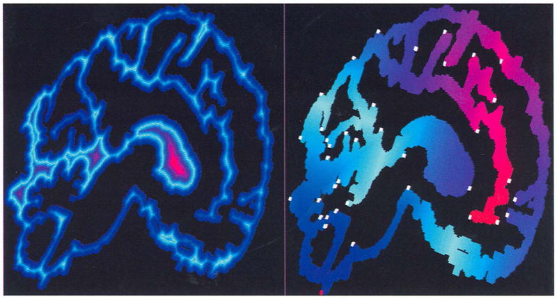
Examples of an BS-fteld (left) and SS-field (right). The object inciudes only one slice with a size of 512 × 512 from a brain MRI data set. The black region consists of outside voxels. The BS-field is generated by voxel coding starting from the object boundaries using the “3-4-5” metric, while the SS-field is created by voxel-coding, starting from the lowest point (marked with a red voxel) using the “1 -2-3” metric. Two fields are displayed with the same color mapping scheme: For each field, the whole code is divided in four equal intervals, then each interval is colored with linear interpolation from two colors. In the code-increasing order, the five colors used are blue, light blue, purple, red, and yellow. The voxels marked with white blocks are local maximum clusters.
The SS-field plays a major role in skeletonization. It provides useful object connectivity and topology information. The SS-coding classifies the object into a collection of clusters. A cluster is defined as a connected set of object voxels with the same SS-code; the SS-code is also called the cluster code. The entire volumetric object can be regarded as consisting of clusters as the smallest unit, instead of voxels. Among clusters, the local maximum cluster (in short: LMcluster) and the branching cluster are of importance. An LMcluster is a cluster which has larger code than all adjacent ones (see Fig. 1 (right)). A merging cluster p is a cluster which has at least two adjacent clusters with the same cluster code one less than p’s. A dividing cluster p is a cluster which has at least two adjacent clusters with the same cluster code one more than p’s. A cluster is called a branching cluster if it is either a merging cluster or a dividing cluster.
Furthermore, the object can be treated as a directed graph if clusters are taken as nodes and node connectivity follows the adjacency of clusters, referred to as a cluster graph. Starting from the reference point—a cluster with the code of zero, the graph extends in the object far away from the RP in the same way as the SS-Coding proceeds. The graph breaks into several branches at dividing clusters, or the branches converge at merging clusters if the object contains a hole. Finally, all the branches end with LMclusters.
The SS-Coding with the “1-2-3” metric is a layer-by-layer voxel coding process. Each layer consists of the voxels with the same SS-code, i.e., a group of clusters with the same code. If the reference point is selected as a boundary voxel (that is true in our selection), each cluster or such a layer of voxels must intersect the object boundary. Theoretically speaking, a cluster is the set of connected intersections between the object and the sphere, with center RP, of radius r (r is the cluster code). Therefore, each cluster can be approximately taken as a cross-section of the object, normal to the related centerline. Now, for each cluster, its medial point can be obtained by checking its voxel BS-code. Here, a medial point of a cluster is defined as a voxel which belongs to the cluster and has the largest BS-code. Obviously, a medial point is centered relative to the object boundary.
In the cluster graph, we replace all nodes (i.e., clusters) with their medial points. Meanwhile, the medial points are connected if their clusters are adjacent, thus, the resulting cluster graph actually becomes a connected centerline network of the object—the object skeleton. The basic idea of our skeletonization is to extract all these centerlines from the cluster graph, forming a connectivity preserved graph—skeletons—which meet all the features mentioned in Section 1.
4.2 Extraction Procedure
4.2.1 Single Centerline Extraction
First, we consider extracting one centerline starling with a cluster c in two steps. Step 1: We first search for c’s medial point by comparing the BS-code of all voxels in c. If there is more than one medial point, the one closest to c’s geometric center is chosen. Then, we employ the SPE procedure in Section 1 relative to the SS-field to extract the path starting with the medial point to the RP, with modifications as follows: Let Pi be a point in such a path, its next point Pi+1 is modified to be Pi’S F-neighbor (rather than any neighbors) with the smallest SS-code. If there is more than one F-neighbor satisfying the condition, geometrically, the F-neighbor in front of Pi has the highest priority in selection, followed consecutively by the following directions: back, left, right, top, or down.
The path extracted after modifications has the following properties: The next point must exist and has an SS-code one less than its immediate predecessor’s, since the SS-field is generated using the “1-2-3” metric. Each point in the path corresponds to the cluster which includes the point, i.e., the path passes through a sequence of clusters. Adjacent points in a path correspond to adjacent clusters in the sequence of clusters. The path ends with the RP if no constraint condition or last point is given. Under the constraints on next point choice, a path is uniquely determined by its first point. Because the medial point of the first cluster is uniquely determined, the path and its associated sequence of clusters are also determined uniquely by the first cluster. Strictly speaking, the path extracted is not the shortest path connecting two endpoints since the next point is restricted to be an F-neighbor, but, hereafter, we still use this notation for convenience. Fig. 2 (left) shows two such paths in red curve and associated sequence of clusters.
Fig. 2.
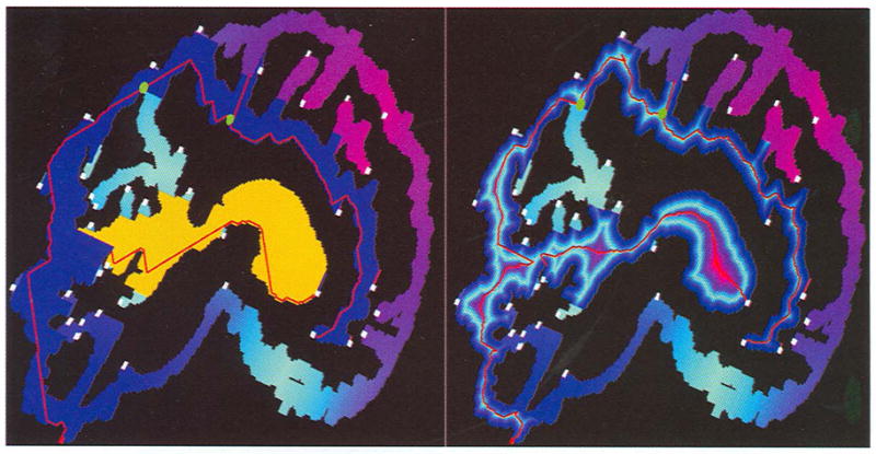
Skeleton extraction and medial point replacement. The left shows two paths extracted (red curves). One starts from the voxel with the largest SS-code and its associated sequence of clusters is represented in blue; the other starts from another LMcluster and ends with an already visited cluster. The associated sequence of clusters is represented in yellow. The right panel shows the results after all the path points are replaced by their medial points, with the associated BS-field in the background. The green spheres in both images are merging clusters in the first path and the line segments connecting these merging clusters and their successors are also displayed.
Step 2: Once extracted, each nonfirst point Pi+1 in the path is replaced by the medial point of its associated cluster. If a cluster has more than one medial point, the one closest to the immediately preceding point Pi (after replacement) is chosen. The path after the replacement is called a Medpath, which is the centerline relative to the sequence of clusters. Obviously, a Medpath is also uniquely determined by its first cluster. Note that adjacent points in a Medpath could not be connected geometrically- Fig. 2 (right) presents the results after the replacement.
4.2.2 Multiple Centerline Extraction
As with extraction of all the centerlines, the following factors must be considered: 1) The extracted centerlines are as long as possible, 2) any two centerlines are not allowed to be coincident in the middle except for at the endpoints, and 3) no centerlines are missed.
Obviously, the paths starting with LMclusters meet Condition 1). Furthermore, in order to obtain all the Medpaths, we must consider Medpaths starting with not only LMclusters, but also other clusters, which have been dropped in the above single Medpath extraction. Because in the search of next cluster, there could be more than one candidate, only one is selected. This case happens at a merging cluster. Given a merging cluster p, the clusters with the code one less than p’s, and adjacent to p, are called p’s successors. Fig. 2 also shows merging clusters marked with green spheres and the line segments connecting the merging clusters and its successors detected as the first path is extracted.
Considering all these factors, we extract skeleton starts with LMclusters recorded in a dynamic Medpath array in a cluster code-decreasing order. First, we extract the Medpath, starting with the largest SS-code following the above procedures for single centerline extraction. Then, for each voxel p and its associated cluster c, we check if c is a merging cluster. If so, there are at least two successors; the ones without including p’s next point in the Medpath are attached to the end of the dynamic array as branches which will be extracted after all LMclusters are processed and c’s identification number is also recorded, indicating those Medpaths which the Medpaths starting with these successors should connect to. Finally, we mark the cluster c. The rest of the Medpaths are extracted in a similar way except that a shortest path extraction ends once the next point belongs to a marked cluster (see Fig. 2 (left)), avoiding the situation where coincident segments are extracted twice. Meanwhile, the identification number of the Medpath which the current Medpath ends with is also recorded for later connectivity considerations.
The marked cluster which another path ends with is a dividing cluster. According to the above procedure, we have the following results: A Medpath starts with an LMcluster or a merging cluster and ends with a dividing cluster or the reference point; two Medpaths cannot cross each other in the middle and may only meet at endpoints.
4.2.3 Implementation
The algorithm is outlined below.
ExtractSkeleton() {
Initialize Medpath[0 : N − 1] with LMclusters and sort in cluster code-decreasing order;
for(i = 0; i < N; i++){//i corresponds to the i-th Medpath
ExtractPath(Medpath, i);
pt = Medpath[i].head;
while (pt){
GetClusterMedialPoint(pt,c,mp); //return pt’s cluster c and medial point mp
GetSuccessor(c, s[0:n-l]); //s[0:n] stores c’s successors
for(j = 0; j < n; j++)
if( s[j] does not include pt → next ){
Medpath[N + +].head ← s[j];
Medpath[N].id1 = i; }
Replace pt with mp and mark cluster c;
pt = pt → next;
}
}
}
Here, Medpath[1 : N] is the dynamic structure array for recording all extracted Medpaths. Each item of the array is a structure which includes at least three parameters: id1, id2, head, corresponding to one Medpath. id1 and id2 record the identification numbers of the other Medpaths which the first and last point of the current Medpath connects to. If the current Medpath starts with an LMcluster or ends with the RP, these parameters are initialized to be a negative value. Parameter head is a head pointer to a voxel chain representing the Medpath. First, it is initialized to point to an LMcluster or an attached successor of a merging cluster, then to a path, and, finally, to a Medpath. The procedure ExtractPath(Medpath, i) extracts a single path starting with a point recorded in Medpath[i].head, Then, the algorithm returns the path and the identification number of the Medpath to which the last point of the current path should be connected, respectively, recorded in Medpath[i].head and Medpath[i].id2.
The procedure described above can extract the whole cluster graph without missing any components since all the clusters are visited during the Medpath extraction because any cluster is either an LMcluster or a nonLMcluster. LMclusters are visited as the first elements leading Medpaths, while nonLMclusters are extracted as intermediate elements of other Medpaths or as branching clusters’ successors leading to other Medpaths.
4.3 Skeleton Refinement, Smoothness, and Connection
The cluster graph extracted above provides a compact representation of the object. However, there are several issues that remain unsolved (see Fig. 2 (right)).
First, the Medpaths after medial point replacement suffer from large intervals between adjacent points, especially in the neighborhood of object branches where partial line segments connecting adjacent points in the Medpath are outside the object. Second, the generated Medpath could self-intersect or fold somewhere. Third, the above procedure only provides information on which Medpaths a Medpath should be connected to, but it does not provide the information on how to connect them. To solve these problems, we introduce a uniform and robust solution using voxel-coding techniques.
4.3.1 Refinement
For the first problem, a general method is to adopt a deformable model using a minimum energy constraint equation or a cost function [25], [14], [19]. The energy constraint equation is based on a potential field, which is a variant of traditional minimum distance fields. As noted in Section 2, calculating constraint equations and adaptive iterations are time-consuming processes. Thus, it is not practical to apply such a constraint equation on many curves at the same time. A simple version of iterative movement towards the medial axis, such as used in [27], is possible. But, this still involves normal evaluation, determination of iterative step length, and processing to avoid sensitivity to the object boundary.
Here, we use the SPE procedure for the refinement, which directly inserts medial points in a large interval between adjacent two points Pi and Pi+1 in a Medpath. We first calculate the shortest path connecting Pi, and Pi+1. This depends on another SS-field, called a local SS-field, which is generated by performing voxel-coding using the “1-2-3” metric with Pi+1 as a seed point until point Pi is reached and coded. The path from Pi to Pi+1 is consequently extracted relative to the local SS-field using the SPE procedure in Section 2.
Then, the corresponding Medpath can be generated by evaluating the associated cluster relative to the local SS-field and medial points relative to the original BS-field. The generated Medpath is inserted in between Pi and Pi+1. This method guarantees that inserted points are centered relative to object boundaries and the intervals meet the requirements. In some extremely complicated cases, the inserted path could still have a large interval, however, which is usually less than the distance of Pi and Pi+1. Fig. 3 (left) shows the results after the refinement on Fig. 2 (right).
Fig. 3.
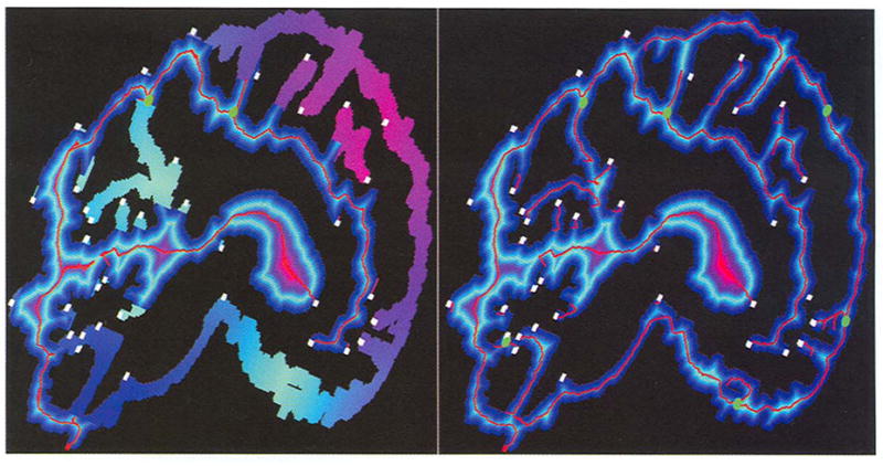
Skeleton refinement and smoothness: on the left are the results after implementing the refinement operation on Fig, 2 (right), where generated paths are knotted or folded in the middle and look like endpoints. On the right are the results after applying refinement and smoothness to all the Medpaths. Note that no replacement, refinement, and smoothness operations are implemented on the final points of all Medpaths.
In implementation, we treat the intervals between adjacent points in a Medpath with a Euclidean distance more than 5.0 as a larger one.
4.3.2 Smoothness
After the refinement, the resulting Medpaths could be more jagged or could self-intersect in the middle. It is necessary to smooth the Medpaths. Here, by smoothness we mean to remove knotted and folded segments only. A curve smoothing method can be adopted for this purpose. As an alternative and for uniformity, we introduce a simple voxel-coding method. Once again, the SPE procedure is utilized for this purpose. Slightly different from the refinement, we first voxelize the Medpath, then perform voxel-coding within the newly voxelized Medpath (as a new object) with one endpoint of the Medpath as the seed point, finally extracting the shortest path starting with the other endpoint until the seed is reached. The newly extracted path is taken as the smoothed Medpath. Employing the SPE strategy, the knotted and folded segments in the original Medpath appear to be tiny branches after the voxelization of the Medpath, thus they are skipped during new Medpath extraction. Fig. 3 (right) shows the results after the refinement and smoothness on all Medpaths (also compare the results between the left and the right with regard to the corresponding Medpaths).
4.3.3 Connection
As for the third problem, an intuitive idea is that, during the path extraction, the branching clusters which other Medpaths originate from or end with are recorded, then, once these Medpaths have been generated later, their endpoints are connected to them. Still, a problem similar to the first issue occurs—the intervals are too large somewhere and the line segments could be outside the object. Furthermore, what is worse is that the clusters which the endpoints are supposed to connect to are not the ones closest to the endpoints, showing a poor connection.
Now, let P1 be the first point of a Medpath and c be another Medpath. We first search the point in c closest to P1. The simple search by comparing the distances from p to the points in c is undesirable because the complex object could not be directly connected along the connection line between P and its 3D closest point in c. As an example, check the Medpath marked with the white voxel with the second largest y-coordinate in Fig. 3 (right). Its last point is closest to a point in a Medpath to its right side, not in the one below, but it is impossible to connect them since they are separated.
Again, we use a method similar to that used for solving the first issue. We take P1 as the seed point, and perform voxel propagation and coding in the object until a point of c is met. The first point met must be the closest one to P1 since the voxel propagation is approximately isotropic. Once the closest point is found, so is the associated local SS-field. Thus, the above refinement method can be used for connection calculation. For the connection of last point of c to another Medpath, a similar method can be used. Fig. 4 shows the final results after the connection operation is implemented on Fig. 3 (right).
Fig. 4.
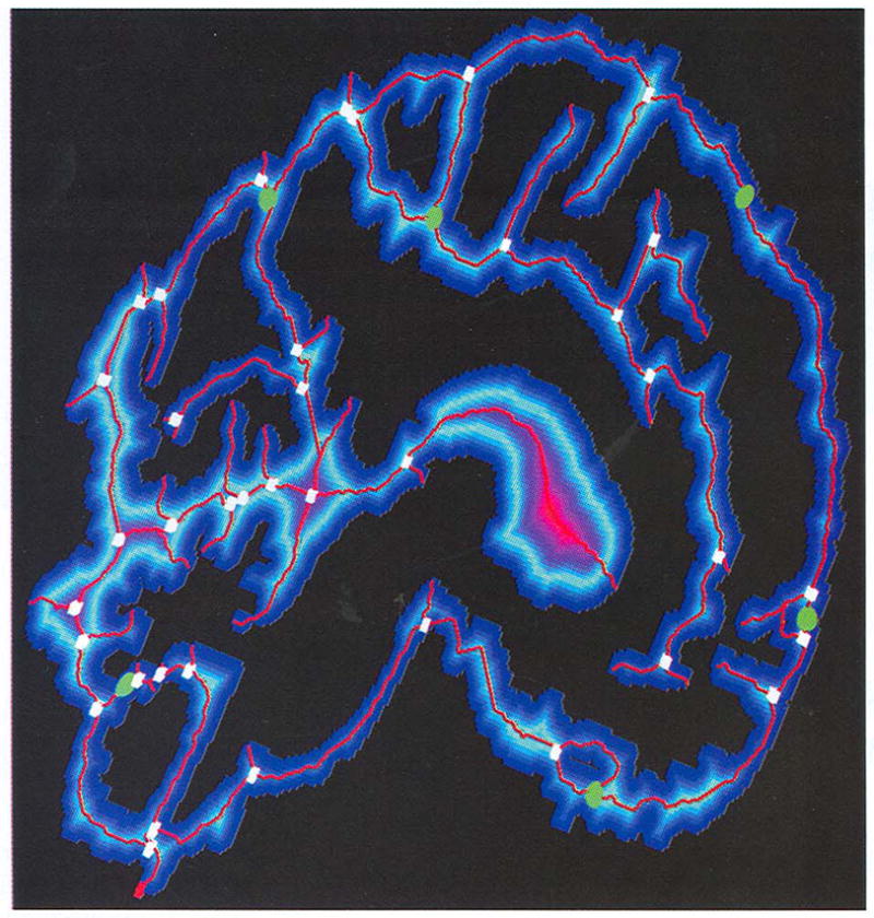
The final results after skeleton connection operations on Fig. 3 (right). The merging clusters are marked with green spheres and dividing clusters with white voxels. Note that each merging cluster corresponds to one hole.
In summary, our complete skeletonization algorithm looks like this.
Skeletonization() {
Select reference point;
Generate BS-field and SS-field;
Search LMclusters;
ExtractInitialSkeleton();
Refine skeleton;
Smooth skeleton;
Connect skeleton;
Display and output skeleton;
}
5 Discussion
Our skeletonization algorithm has the following desirable properties.
5.1 Connectivity and Centeredness
Our skeleton is interpreted as the collection of all the Medpaths. First, this is a compact representation of the object. The SS-coding is an adjacency-based region growing process which starts with a single seed point. It detects, encodes all connected components of the objects and it further makes all the clusters ordered according to their geometry adjacency and cluster code. The skeletonization process extracts all the sequences of clusters without missing any components and represents the associated shortest paths, which are further replaced by their Medpaths. A series of operations do not change the topology of initial skeletons. Second, all the Medpaths are connected; the connectivity of a Medpath itself is determined by the adjacency of the associated sequence of clusters. Disconnectivity could only happen between Medpaths, but this is avoided by the skeleton connection operation. Finally, whenever they are extracted, paths are replaced by their Medpaths; the centeredness is enforced by the BS-field.
Selection of the reference point influences the construction and geometry of individual centerlines and the choice of coding scheme influences the density and shape of the initial skeleton. The whole skeleton topology finally converges into a fixed configuration—medial axes—after the skeleton replacement, refinement, smoothness operations.
5.2 Computation Complexity
The whole algorithm consists of both SS-field and BS-field calculation, skeleton extraction, replacement, refinement, smoothness, and connection operations. For each step, a voxel is visited at most several times and each visit only involves assignment of a value or reversing the sign. Almost every step employs the ESP procedure, resulting in a systematic and uniform solution.
To a degree, clusters, in our algorithm, simulate the cross-sections of the objects and the medial points of clusters simulate the centers of the cross-sections. The adjacency and code of clusters determine the cluster order. All related computation is straightforward. In comparison, the related methods [4], [1], [7] had difficulties in cross-section calculation and their density and order determination, especially at branchings.
5.3 Sensitivity
No matter what distance transform or thinning technique is applied, traditional methods generate skeletons on the basis of a local template operation for simple point [12], [10], [11] or saddle point [16] detection. This is very sensitive to boundary details and noise, especially those of 3D objects.
Our skeleton calculation is based on clusters, rather than single voxels; the connectivity of Medpaths is determined by the adjacency of clusters, rather than the geometrical relationship of adjacent voxels. The algorithm does not require any preprocessing on input binary objects. Furthermore, no iterative process is required for the centeredness. The centeredness is implemented by direct medial point replacement without testing if a point is stuck at local noise or in complicated object boundaries during deformation as in [19], [18], overcoming the sensitivity.
5.4 Smoothness, Fineness, and Ease of Control
Our voxel-coding produces one-voxel-wide skeletons. Traditional 3D techniques for extracting skeletons usually generate spurious trivial branches. Gagvani [7] provides a parameter, allowing the control of thiness of skeleton, but not branches, In contrast, our algorithm provides a length parameter to control the object branches. The extraction process naturally provides the length of a centerline. Furthermore, the skeleton smoothness operation provides a robust method to remove the folded or knotted segments of centerlines. This is significant in many applications which need to further process generated skeletons. For example, the modeling of cerebral sulci depends on generated skeletons extracted from brain gray/white matter for analysis and measurement of brain function. A set of discrete voxels used to form a skeleton would make them cumbersome for further processing. In our algorithm, extracted centerlines can be easily approximated and optimized to generate continuous curves.
5.5 Object Hole Detection
Our voxel-coding-based skeleton algorithm also provides a scheme for object hole detection. Now, we restrict the object to be a 2D region. An object hole is defined as a set of all F-connected outside voxels surrounded by a connected set of object voxels. Here, a voxel is treated as a pixel within a plane; F-connected means grid edge-shared. Let MC be the set of all merging clusters and successor(p) be the number of successors of merging cluster p, we have the result as follows:
| (1) |
Let p be a merging cluster; its each successor corresponds to a cluster sequence extracted by using the procedure for single centerline extraction in Section 4.2, starting with the successor. Obviously, the cluster sequences relative to p’s any two successors p1 and p2, together with p, construct a closed loop since these sequences meet in the middle or at the reference point and both p1 and p2 are adjacent to p. The loop is denoted by the triple (p1, p2, p). A pair of successors (p1, p2) is called contiguous if there is a connected set of outside voxels surrounded by the loop (p1, p2, p) and if p1, p2, and p are all adjacent to the set. By definition, the set constructs a hole h.
We prove that h cannot be detected by another contiguous pair of successors ((q1, q2)) of a certain merging cluster q (note q could be p). If so, the loop (q1, q2, q) also surrounds h, thus these two loops must be nested rather than crossed according to the path extraction procedure, resulting in that q1, q2 and q cannot be adjacent to h simultaneously since p, p1 and p2 are adjacent to it. Therefore, different contiguous pairs of successors correspond to different hole. Since there are at least successor(p) − 1 such pairs of successors for each merging cluster p, thus HoleNumber ≥ Σ p∈MC(successor(p) − 1).
On the other hand, each hole h can be detected by a contiguous pair of successors of a certain merging cluster. According to the definition of a hole, there is a set of object voxels adjacent to the hole. No matter what a reference point is chosen, the set can form only one contiguous pair of successors. Obviously, different holes cannot be detected by the same contiguous pair of successors. In other words, different holes correspond to different pairs of successors. Thus, HoleNumber ≤ Σ p∈MC(successor(p) − 1). Thus, the above equation holds.
The choice of the reference point influences the construction of merging clusters, but does not influence the above result. Fig. 5 illustrates LMclusters, branching clusters, and hole detection relationships relative to different reference points. Fig. 4 also shows all holes detected by merging clusters marked in green sphere.
Fig. 5.
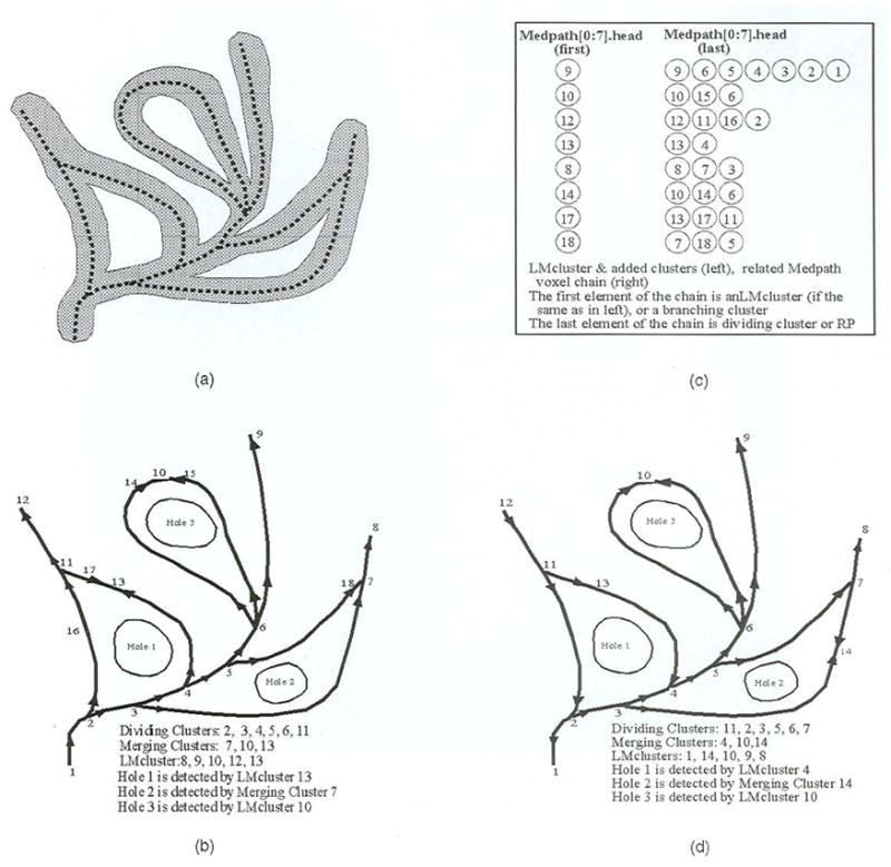
Object, skeleton, special cluster, object hole detection, Medpath extraction, and their relationships to the reference point, (a) Object and skeleton, (b) Special clusters, the cluster graph, and holes with point 1 as RP. (c) Medpath extraction relative to (b). (d) The situation after the RP is changed to point 12.
A possible case is that noise could cause numerous false holes. Fortunately, the length of a Medpath is an ideal parameter for the control of tiny skeleton segments.
6 Applications and Results
Skeletonization introduces alternative shape descriptors. It promises to become a powerful tool for operations such as grouping, feature tracking, path planning, and bridging the gap between low-level and high-level representation of objects. In this section, we introduce the application of our skeletonization algorithm and discuss the implementation results on several 3D data sets.
Path planning is a direct application. Usually, a path provides an useful cue for navigation inside objects, such as human organs. Given two points, our voxel-coding flexibly extracts a shortest path connecting them. The SPE procedure can be applied, after SS-coding is performed with one point as the seed, and ends when the other point is reached and encoded. This method has been discussed in [26].
We have applied the algorithm to surface reconstruction from contours [28]. In order to tile contours from adjacent slices, such as four contours in one slice and two contours in the adjacent slice (see Fig. 6), we construct an intermediate graph in between and then connect contours in both slices to them. The graph is designed as a simplified skeleton extracted from the difference area of adjacent contours. The difference area is the total area surrounded by the vertical projections of contours, excluding the internal region of overlap. The simplified skeleton consists of all centerline segments, which surround or connect the overlap, i.e., holes. In other words, these segments connect both merging and dividing clusters. Our voxel-coding-based algorithm provides a robust solution since it supports removal of tiny branches and object hole detection. Fig. 6 shows the simplified skeleton on the surface reconstructed from contours in adjacent slices.
Fig. 6.
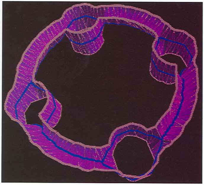
The simplified skeletons marked in blue extracted from a difference area of contours in white (four in the lower slice and two in upper slice).
MRI and CT data sets in medical areas have been widely used for visualization and modeling of the human body. Four 3D medical data sets were selected for our algorithm, test, including brain (MRI), colon (CT), airway, and lung (CT). Table 1 provides the details of these data sets. The first column lists data resolution and the total number of object voxels. The second column lists associated images generated by our algorithm. In each image, the original data sets, i.e., the binary objects, are displayed using transparent voxels without lighting effects; the related skeletons are shown in red. Each image is the result after the original data set goes through skeleton extraction, replacement, refinement, smoothness, and connection. The third column lists times (in seconds) without including the data input and display process, measured when running on an SGI Power Onyx-R10000 CPU. The fourth column lists the number of centerlines; the last column lists the the maximum number of layers relative to the SS-field and the BS-field. The SS-field is generated with the “1-2-3” metric, while the BS-field is generated with the “3-4-5” metric. To a degree, these indices also reflect the degree of data complexity.
TABLE 1.
Algorithm Test Data and Results
6.1 MRI Brain Data
This data set shows where the cerebral sulci are located. The generated skeletons outline the sulci (see Fig. 7). The reference point is selected as the point with the smallest y-coordinate. One hundred and ten LMclusters are formed and 19 merging clusters are detected. Fig. 7 shows the results after tiny branches are cut, where the color scheme follows the same method as in Fig. 1 (left). The only difference is that this data set consists of nine slices rather than one.
Fig. 7.
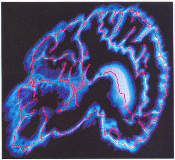
Skeletons extracted from a brain MRI data set.
6.2 CT Colon Data
The initially generated skeleton without control is spurious. Fig. 8 shows results after the branches with length less than 80 (in voxels) are pruned. The skeleton exactly describes the outline of the twisted colon with the same color scheme as in Fig. 1 (right). The point marked with a red solid cube is the reference point. It is worth mentioning that, if only the longest centerline is required, the calculation time can be greatly reduced by commenting out detection of merging clusters and extraction of Medpaths starting with non-LMclusters.
Fig. 8.
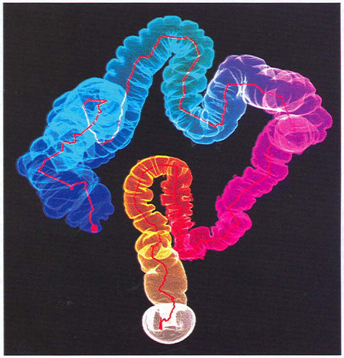
Centerline extracted from a human colon CT data set.
6.3 Airway Tree Data
This airway is segmented from a CT lung data set. The binary data is very sparse and there are many isolated points disconnected from the major component. In Fig. 9, only skeletons from the major component are extracted. From generated pictures, some segments of skeletons pass through the object boundary; no matter how thin the original object is, the algorithm can obtain correct results.
Fig. 9.
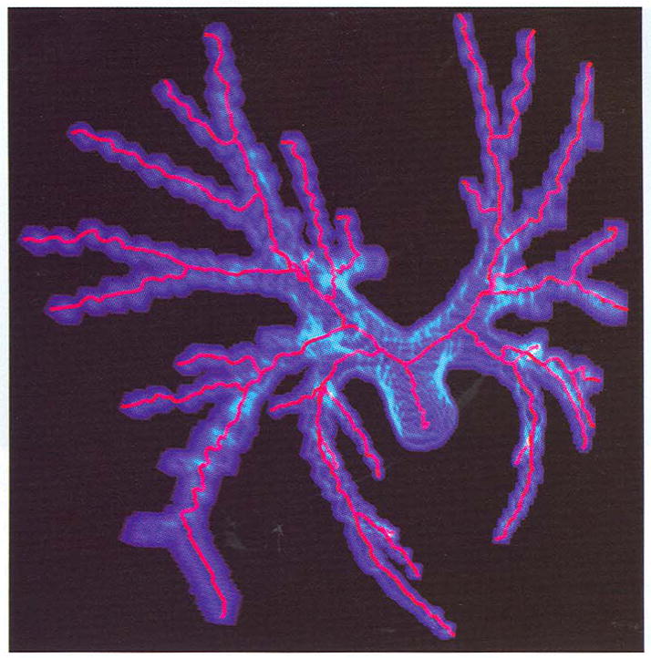
The skeletons of the airway tree extracted from a human lung CT data set.
6.4 CT Lung Data
The binary data is segmented from a CT lung data set. The segmented data shows the human “skeleton,” a bony framework. Our algorithm extracts the thinnest skeleton (see Fig. 10). This is a good example for low resolution display. For the display of 1,483,386 object voxels, it is difficult to render them interactively. However, this becomes easer when only the generated skeletons are displayed.
Fig. 10.
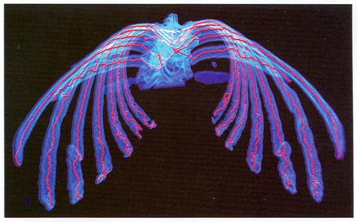
The finest skeleton of a real human skeleton extracted from a human lung CT data set.
7 Conclusions
In this paper, we describe an efficient skeletonization technique—voxel-coding. Two types of voxel-coding have been proposed for the skeletonization of 3D complex objects. The SS-coding converts objects into a directed cluster graph, while BS-coding generates a traditional minimum distance field. The core idea of our algorithm is the SPE procedure. The SS-coding-based SPE procedure has been applied, respectively, for skeleton extraction, refinement, smoothness, and connection operations; the BS-coding is combined for medial point replacement wherever a shortest path is extracted.
Our voxel-coding technique has significant advantages over traditional methods: connectivity preservation, centeredness satisfaction, straightforward computation, no sensitivity to object boundary complexity, and smooth, fine, easy-to-control, and ready-to-parameterize skeleton generation. An additional benefit of our voxel-coding is that object holes or cycles are also easily detected without additional computational cost. Several applications of our algorithm are introduced and a range of real 2D and 3D data sets were used to test the algorithm, documenting its efficiency.
Recently, voxel-coding has been successfully employed for reconstructing 3D objects from unorganized points or range data, We believe voxel-coding techniques will be used in more applications in the future.
Acknowledgments
We thank Dr. Paul Thompson for help reading drafts and pointing out errors. We would like to thank the anonymous referees for their helpful suggestions, Prof. Arie Kaufman and Dr. Rui Chiou for providing colon and lung data sets, and Dr. Milan Sonka for the airway tree data set. This work was supported by the U.S. National Science Foundation DBI 9601356 and the U.S. National Institutes of Health NS 38753, NCRR RR05956, and P41 RR13642.
Biographies
Yong Zhou received his MS in mathematics from Zhejiang University in 1991 and his PhD in computer science from Tsinghua University, China, in 1995. He is a research assistant professor at the University of California, Los Angeles. From August 1996 to July 1997, he was a postdoctoral fellow at the State University of New York, Stony Brook, and, from August 1995 to July 1996, a postdoctoral fellow at the University of Kentucky. His research interests include computer graphics, volume visualization, geometrical modeling, computer vision, image processing, and applications on medical images. He is a member of the IEEE Computer Society. For more information, see http://www.loni.ucla.edu/~yzhou.

Arthur W. Toga received his MS and PhD degrees from St. Louis University. He is a professor in the Neurology Department at the UCLA School of Medicine. He is the editor-in-chief of the Journal of NeuroImage. He is director of the Laboratory of Neuro Imaging, and co-director of the Brain Mapping Division. His research interests include brain mapping, modeling, cognitive neuroscience, and brain structure function visualization. He is a member of the ACM and the IEEE Computer Society. For more information, see http://www.loni.ucla.edu/people/AWT.html.

References
- 1.Arcelli C, Sanniti di Baja G. Finding Local Maxima in A Pseudo-Euclidean Distance Transform. Computer Vision, Graphics, and Image Processing. 1988;43:361–367. [Google Scholar]
- 2.Ablameyko SV, Arcelli C, Sanniti di Baja G. Hierarchical Decomposition of Distance Labeled Skeletons. Int’l J Pattern Recognition and Artificial Intelligence. 1996;10(8):957–970. [Google Scholar]
- 3.Blum H. Proc Symp Models for the Perception of Speech and Visual Form. Cambridge, Mass.: MIT Press; 1967. A Transformation for Extracting New Descriptors of Shape. [Google Scholar]
- 4.Rosenfeld A, Pfaltz JL. Sequential Operations in Digital Picture Processing. J ACM. 1966;13:471–494. [Google Scholar]
- 5.Hong L, Muraki S, Kaufman A, Bartz D, He T. Proc SIGGRAPH ’97. Los Angeles: Aug, 1997. Virtual Voyage: Interactive Navigation in the Human Colon; pp. 27–34. [Google Scholar]
- 6.Silver D, Wang X. Proc IEEE Visualization ’96. San Francisco: 1996. Volume Tracking; pp. 157–164. [Google Scholar]
- 7.Gagvani N. MS thesis. Dept. of Electrical and Computer Eng., Rutgers Univ.; New Brunswick, N.J.: Jun, 1997. Skeletons and Volume Thinning in Visualization. [Google Scholar]
- 8.Helman JL, Hesselink L. Visualization of Vector Field Topology in Fluid Flows. IEEE Computer Graphics and Applications. 1991;11(3):36–46. [Google Scholar]
- 9.Itoh T, Yamaguchi Y, Koyamada K. Proc IEEE Visualization ’96. San Francisco: 1996. Volume Thinning for Automatic Isosurface Propagation; pp. 303–310. [Google Scholar]
- 10.Pavlidis T. A Thinning Algorithm for Discrete Binary Images. Computer Graphics and Image Processing. 1980;13:142–157. [Google Scholar]
- 11.Mukerjee J, Das PP, Chatterji BN. Thinning of 3D Images Using the Safe Point Thing Algorithm (PTA) Pattern Recognition Letters. 1989;10:167–173. [Google Scholar]
- 12.Tsao YF, Fu KS. Proc IEEE Pattern Recognition and Image Processing Conf. 1982. A 3D Parallel Skeleton wise Thinning Algorithm; pp. 678–683. [Google Scholar]
- 13.Mao CM, Sonka M. A Fully Parallel 3D Thinning Algorithm and Its Applications. Computer Vision and Image Understanding. 1996;64(3):420–433. [Google Scholar]
- 14.Miller JV, Breen DE, Lorensen WE, O’Bara RM, Wozny MJ. Geometrically Deformed Models: A Method for Extracting Closed Geometric Models from Volume Data. Proc SIGGRAPH ’91. 1991:217–226. [Google Scholar]
- 15.Borgefors G. Distance Transformations on Digital Images. Computer Vision Graphics Image Processing. 1986;34:344–371. [Google Scholar]
- 16.Niblack CW, Gibbons PB, Capson DW. Generating Skeletons and Centerlines from the Distance Transform. CVGIP: Graphical Models and Image Processing. 1992 Sept;54(5):420–437. [Google Scholar]
- 17.Dorst L. Proc Eighth Int’l Conf Pattern Recognition. Paris: Oct, 1986. Pseudo-Euclidean Skeletons; pp. 286–289. [Google Scholar]
- 18.Payne BA, Toga AW. Distance Field Manipulation of Surface Models. IEEE Computer Graphics and Applications. 1992;12(1):65–71. [Google Scholar]
- 19.Leymarie F, Levine MD. Simulating the Grass Fire Transform Using an Active Contour Model. IEEE Trans Pattern Analysis and Machine Intelligence. 1992 Jan;14(1):56–75. [Google Scholar]
- 20.Paik DS, Beaulieu CF, Jeffrey RB, Rubin GD, Napel S. Automated Flight Path Planning for Virtual Endoscopy. Medical Physics. 1998;25(5):629–637. doi: 10.1118/1.598244. [DOI] [PubMed] [Google Scholar]
- 21.Saito T, Toriwaki JI. New Algorithms for Euclidean Distance Transformation of an n-Dimensional Digitized Picture with Applications. Pattern Recognition. 1994;27(11):1,551–1,565. [Google Scholar]
- 22.Ogniewicz RL, Kubler O. Hierarchic Voronoi Skeletons. Pattern Recognition. 1995;28(3):343–359. [Google Scholar]
- 23.Sherbrooke EC, Patrikalakis NM, Brisson E. An Algorithm for the Medial Axis Transform of 3D Polyhedral Solids. IEEE Trans Visualization and Computer Graphics. 1996 Mar;2(1):44–61. [Google Scholar]
- 24.Sheehy DJ, Armstrong CG, Robinson DJ. Shape Description by Medial Surface Construction. IEEE Trans Visualization and Computer Graphics. 1996 Mar;2(1):62–72. [Google Scholar]
- 25.Terzopoulos D, Fleischer K. Deformable Models. The Visual Computer. 1988;4:306–331. [Google Scholar]
- 26.Zhou Y, Kaufman A, Toga AW. 3D Skeleton and Centerline Generation Based on an Approximate Minimum Distance Field. The Visual Computer. 1998;14(7):303–314. [Google Scholar]
- 27.Zhou Y, Thompson P, Toga AW. Extracting and Representing the Cortical Sulci. IEEE Computer Graphics and Applications. 1999 May/June;19(3):49–55. doi: 10.1109/38.761550. [DOI] [PMC free article] [PubMed] [Google Scholar]
- 28.Zhou Y, Toga AW. Voxel Coding for Tiling Complex Volumetric Objects. submitted for publication, 1999 ( http://www.loni.ucla.edu/~yzhou/retile.html)
- 29.Zhou Y, Toga AW. Turning Unorganized Points into Contours. doi: 10.1109/PCCGA.2000.883947. submitted for publication, 1999 ( http://www.loni.ucla.edu/~yzhou/UptRecons.html) [DOI] [PMC free article] [PubMed]


