

Abstract
Tripeptidyl peptidase II (TPP II) is the largest known eukaryotic protease (6MDa). It is believed to act downstream of the 26S proteasome cleaving tripeptides from the N– termini of longer peptides and it is implicated in numerous cellular processes. Here we report the structure of Drosophila TPP II determined by a hybrid approach: The structure of the dimer was solved by x–ray crystallography and docked into the three– dimensional map of the holocomplex obtained by single-particle cryo-electron microscopy. The resulting structure reveals the compartmentalization of the active sites inside a system of chambers and suggests the existence of a molecular ruler determining the size of the cleavage products. Furthermore, the structure suggests a model for activation of TPP II involving the relocation of a flexible loop and a repositioning of the active–site serine, coupling it to holocomplex assembly and active site sequestration.
Giant proteases are homo–multimeric assemblies of extraordinary size which act downstream of the proteasome. Moreover, they are capable of substituting for some of the proteasome’s metabolic functions1. The archetypal giant protease is tricorn protease, which was originally found in the archaeon Thermoplasma acidophilum2,3. Its 121 kDa subunits form hexamers4, which can assemble further into icosahedral capsids with a mass of 14.5 MDa5. The functional equivalent of tricorn protease in eukaryotic cells is TPP II, a large spindle–shaped complex with a molecular weight of ~ 6 MDa. TPP II is a serine protease of the subtilisin class with an exopeptidase activity that cleaves off tripeptides from the N–termini of peptides such as those released by the proteasome. In addition to exopeptidase activity, TPP II also has endopeptidase activity, but this activity is more than two orders of magnitude lower6. TPP II has been implicated in the trimming of proteasomal degradation products for MHC class I antigen presentation7,8, however, the precise role of TPP II in antigen processing is still a matter of some controversy.9,10,11. TPP II is upregulated in diseases that involve increased and uncontrolled proteolysis12,13. TPP II knockout mice are viable but have a shortened life span, which is associated with the activation of cell death programs and an immunosenescence–like phenotype14. A membrane–associated variant of TPP II degrades the endogenous satiety agent cholecystokinin–8 (CCK–8)15 involved in fat metabolism, which makes TPP II an interesting target for the treatment of obesity16.
Bioinformatic as well as biochemical studies indicated that TPP II contains a subtilisin–like domain, but the functional role of the larger part of the polypeptide chain remained enigmatic. Earlier single–particle cryo–electron microscopy (cryo–EM) investigations had shown that the overall structure of TPP II is a spindle–shaped assembly composed of two twisted strands; each strand contains 10 repeat segments (dimers) in which the two monomers are oriented back–to–back17. Functional studies had shown that TPP II dimers have only nominal activity (which we refer to here as being in an inactive state) and the specific activity of TPP II increases with the number of assembled dimers; this is indicative of a contact–induced activation mechanism18.
For a mechanistic understanding of TPP II and its unique architecture, a high–resolution structure of the fully assembled complex is indispensable. Since the structure of TPP II is highly dynamic in vitro – the strand length is dependent on protein concentration giving rise to polymorphism18 – its crystallization has remained an elusive goal. To overcome this problem, we have used the following strategy: we dissociated the multimeric spindles into dimers and treated them such that re-association was inhibited. To this end, many modifications (fusions, deletions, site–directed mutagenesis and chemical modifications) were tried – without success. We found that the detergent octylglucoside (OG) could stabilize the dimers obtained from the dissociated spindles and prevent their reassociation upon concentration. TPP II dimers prepared in this way were suitable for crystallization trials and led to the production of well–ordered crystals. Having crystals of TPP II dimers allowed us to apply a hybrid approach combining x–ray crystallography and single–particle cryo–EM, where the 3.2Å structure of the TPP II dimer was docked into an improved EM envelope (14Å resolution) of the TPP II spindle to generate a pseudo–atomic model of the TPP II holocomplex. This structure provides new insights into the functional mechanism of the intriguing supramolecular architecture of TPP II and the molecular basis for its assembly–dependent activation.
RESULTS
Overall structure of the TPP II dimer
Crystals of the TPP II dimers, grown in the presence of OG detergent, have the space group P41212 with one monomer per asymmetric unit. The electron density map determined by single wavelength anomalous dispersion (SAD) phasing of diffraction data collected at the selenium absorption peak was of good quality (Supplementary Fig. 1). Data collection and refinement statistics are presented in Table 1.
Table 1.
Crystallographic Statistics
| Se-Met (peak) | |
|---|---|
| Data collection | |
| Space group | P41212 |
| Cell dimensions | |
| a, b, c (Å) | 126.37, 126.37, 213.98 |
| α, β, γ (°) | 90.00, 90.00, 90.00 |
| Resolution (Å) | 50-3.14 (3.25-3.14) |
| Rsym | 0.117 (0.593)** |
| I/σI | 22.14 (2.67) |
| Completeness (%) | 98.9 (89.9) |
| Redundancy | 14.3 (9.5) |
| Refinement | |
| Resolution (Å) | 50 3.14 |
| No. reflections | 30956 |
| Rwork/Rfree | 0.241/0.293 |
| No. atoms | |
| Protein | 9464 |
| B-factors | |
| Protein | 92.18 |
| R.m.s. deviations | |
| Bond lengths (Å) | 0.003 |
| Bond angles (°) | 0.698 |
Values in parentheses are for the highest-resolution shell.
The relatively high value is a reflection of the strong anomalous differences in the higher resolution zones.
Based on the crystal structure, the TPP II sequence can be divided into three parts (Fig. 1a): (i) The subtilisin–like domain, which between the catalytic Asp and His residues contains the long insert (~ 200 amino acids) typical for all TPP II homologues, (ii) a central domain rich in β–sheets, and (iii) a C–terminal domain comprising a twelve–helix bundle. The general shape of a monomer is that of a bottomless “bowl” with a curved protrusion (Fig. 1b). In the TPP II dimer, the monomers are oriented back–to–back; the opening at the bottom of each bowl is sealed off by the adjoining monomer, the protrusions of the two monomers come into contact to form the “handle” of a dimer (Fig. 1b). The protrusion is formed by the C–terminal region of the sequence and part of the insert within the subtilisin– like domain (Fig. 1a-c). The subtilisin–like domain encompasses only a small portion of the entire structure and is located at the rim of the bowl, which is otherwise formed primarily by the central domain.
Figure 1.

Crystal structure of the TPP II dimer. (a) Schematic representation of the primary structure of Drosophila TPP II depicting the domains found in the crystal structure. The subtilisin–like domain in yellow (residues 1–522) contains the active–site residues (red stars) and the loop L2 (residues 441–460), loop L1 (residues 408–417) that is unique to TPP II, and a long insertion (I) in orange (residues 75–266); a central domain (residues 523– 1098, green/gray) containing the “L3” loop (residues 1027–1098); a C–terminal domain (residues 1099–1354, blue). The black bar above denotes segments involved in the formation of the bowl (B) or handle (H). (b) Surface representation of a TPP II dimer (color scheme as in a); active site in red. The two monomers are oriented in back–to–back fashion; the open bottom of the bowl–like domain of one monomer is closed off by the adjoining monomer (white arrow). The protrusions of the two bowls meet to form a handle. (c) Ribbon diagram of a monomer. The active–site residues are shown in stick format (red). The missing loops, (L1, L3), and the missing N–terminal fragment of the loop L2 are designated by dashed lines. (d) Close–up view of the active–site region of the inactive TPP II dimer (yellow) superposed onto that of subtilisin Carlsberg (gray; accession code 1CSE). Active– site residues of TPP II (red) and subtilisin (gray) are shown in stick format. The major differences between the two structures are in the loop regions; notably the L2 loop and the adjoining α–helix where the active–site serine, Ser462, is located. All structural renderings were made with PyMOL35 unless otherwise noted.
The structure of the subtilisin–like domain is quite similar to prototypical subtilisin – nearly all of the secondary structure elements are conserved. Nevertheless, some conspicuous differences between subtilisin and the TPP II subtilisin–like domain exist. They involve conformational differences of a number of loops that differ in both length and sequence, but are conserved in their respective family members. Most notable is the ~ 200 amino acid insertion (residues Gly75–Val266) (Fig. 1a), which is absent in subtilisin. This stretch of residues forms a supporting structure between the bowl and the curved protrusion; its helical region integrates into the twelve–helix bundle of the C–terminal domain (Fig. 1b,c).
Density for most of the structure was observed; the disordered regions were limited to a few predicted loop regions, which were not modelled due to lack of density or weak density (Fig. 1a, c). These loops include residues Asn90–Pro112, loop “L1” (Glu408–Gly417), which is highly conserved and unique to the TPP II family, residues Gly442–Gln456 of loop “L2” (Gly441–Gly460), which is likewise highly conserved and contains active–site residue Ser462 at its C–terminal side, and loop “L3” (Lys1027–Lys1098) which is substantially shorter in human TPP II and is prone to nicking in both purified Drosophila and human TPP II with no observable effect on activity.
Active site and substrate–binding cleft
The overall arrangement of the catalytic triad residues (Asp44, His272, and Ser462) in the crystal structure of the TPP II dimer is similar to that of other subtilisin family members. Superposition of the subtilisin–like domain of TPP II and subtilisin Carlsberg reveals that residues Asp44 and His272 are positioned like the equivalent residues in subtilisin (Fig. 1d); the carboxylate of the aspartate is in the same plane as the imidazole ring of the histidine. Such geometry is important for proton transfer from histidine to aspartate and is known to be critical for activity in subtilisin19. However, the α–carbon of the active–site serine, Ser462, of the inactive TPP II dimer is displaced ~ 5 Å away from where it would be expected based on its equivalent in subtilisin Carlsberg, Ser221 (Fig. 1d). This displacement is associated with the different secondary structures of the two proteins in this region: Ser221 of subtilisin is situated within the N–terminal last turn of an α–helix while the same segment in the inactive TPP II dimer is “unwound”, displacing the active–site serine away from the expected location. Notably, the amino acid sequence of this segment is identical in subtilisin and TPP II. In both proteins, the respective segment is linked to the rest of the structure through a loop, which for TPP II is referred to here as L2 (Gly441–Gly460; see Fig. 1c, d). The two loops are quite different in sequence but highly conserved within their respective families.
In the crystal structure of the TPP II dimer, a large segment of L2 (Gly442–Gln456) has poor density and hence is not modelled. Only three residues at its C–terminal end are visible, and these residues, which are located adjacent to the active–site serine Ser462, are bound to the substrate binding cleft (Fig. 2). This is consistent with our earlier biochemical data showing that TPP II dimers have only residual peptidolytic activity18. The binding of the three L2 loop residues appears to stabilize the active–site residue, Ser462, in an inactive conformation by displacing it away from the expected position.
Figure 2.

Stereo–view of the substrate–binding cleft. The substrate–binding cleft (in stick format) is formed by Ser310–Glu312 and Ser340–Gly342. The conserved residues Asp305 and Arg307 at the N–terminal side of Ser310–Glu312 form a salt bridge that participates in the stabilization of the strand conformation. A three–residue segment (Leu457–Asn459) of loop L2 is bound to the cleft (in stick format, green) and forms an antiparallel β–sheet with the cleft–forming strand (Ser340–Gly342). The binding cleft is delimited by a pair of highly conserved glutamate residues (Glu312 and Glu343), allowing only three residues to be bound in the cleft. The hydroxyl group of the highly conserved residue Tyr876 forms a hydrogen bond with the side chain of Glu312. Active–site side–chain residues are shown in brown for reference, the strands involved in formation of the binding cleft (in stick format, light blue), the two glutamate residues in dark blue, and, for visual clarity, the side chains for residues 303–314 and 338–344 (excluding residues 305, 307, 312, and 343) are omitted.
The TPP II substrate–binding cleft (Fig. 2) is formed by two strands, Ser310–Glu312 and Ser340–Gly342. The three residues of loop L2 (Leu457–Asn459) that are bound to the binding–cleft in the crystal structure, form a two–stranded antiparallel βsheet with only one of the two binding–cleft strands (Ser340–Gly342). This is in contrast to the situation in subtilisin, where bound substrates form a three–stranded anti–parallel β–sheet with both strands of the binding cleft20. This difference in substrate–enzyme interactions is attributable to a conformational difference between Ser310–Glu312, one of the two strands forming the binding cleft in TPP II, and its counterpart in subtilisin. At the N–terminal side of Ser310– Glu312 there is a sequence stretch conserved in the TPP II family, containing two residues (Asp305 and Arg307) that form a salt bridge, which contributes to the stabilization of the strand conformation. This stretch of conserved residues is not found in subtilisin. As a consequence, the cleft is wider in TPP II.
In the endopeptidase subtilisin, substrates in the binding cleft are able to occupy position S4 (designated according to the naming convention of Schechter and Berger21), whereas two highly conserved negatively charged residues, Glu312 and Glu343, block the equivalent position in TPP II. These two glutamates resemble the double–Glu motifs found in Dipeptidyl peptidase IV22, Tricorn factor F123 and Prolyl–tripeptidylpeptidase24,25 which coordinate the positively charged N–terminus of peptide substrates via ionic interactions. Therefore, we mutated either of the two glutamates into glutamine residues to probe their potential interaction with the substrate and found that both substitutions lead to a drastic increase in KM and decrease of the cleavage rate (Supplementary Table 1). As evidenced by electron microscopy (see Supplementary Table 2), the unique spindle structure of the complex was conserved in these mutants. Thus, the effects observed are not attributable to improper folding and assembly of TPP II. Without the binding energy provided by the interaction of either Glu312 or Glu343 with the free N–terminus of the peptide substrate, the affinity of a substrate like AAF–Amc for the binding site is extremely low. This was shown by studying the kinetic parameters of the N–terminally blocked substrate Succinyl–AAF–Amc: This substrate was not cleaved at a detectable level by the wild type or the mutants. In a competition assay with AAF–Amc, no affinity of the blocked substrate for the active site was detected. Thus, cleavage at amino acid positions 1 or 2 is not a substantial competing reaction. Therefore, by strongly binding the N–terminus at binding position S3 of the substrate–binding cleft, Glu312 and Glu343 appear to create a molecular ruler providing exact cutting of tripeptides.
The side chain of Glu312 in TPP II forms a hydrogen bond with the hydroxyl group of the highly conserved residue Tyr876, while the side chain of Glu343 forms a hydrogen bond with the backbone amine of the loop L2 residue Leu457, which is the N–terminal residue of the tripeptide segment of L2 bound to the binding cleft. The interactions of the residues of the substrate–binding cleft, notably those involving Glu343, with the three loop L2 residues are expected to be rather similar to interactions with substrates destined for endopeptidolytic processing.
Assembly–dependent activation switch
Biochemical studies have shown that the specific activity of a TPP II strand is proportional to the number of dimer–dimer contacts18, suggesting that these contacts trigger the activation process. The crystal structure of the TPP II dimer explains why, prior to assembly, dimers have only residual activity: the active–site Ser462 is displaced and a three–residue segment of loop L2, adjacent to the Ser462, is bound to the substrate–binding cleft. For activation the three–residue segment of loop L2 must be removed from the substrate–binding cleft and Ser462 must be repositioned into an active conformation.
The unwound N–terminal segment of the α–helix containing the active–site residue Ser462 in the TPP II dimer (Fig. 3a) has a different hydrogen–bonding pattern from that seen in subtilisin (Fig 3b), yet the amino acid sequences of both proteins in this segment are identical (Supplementary Fig. 2). In subtilisin, residue Thr220, which flanks active–site residue Ser221, forms hydrogen bonds with Asn155, which is highly conserved and is known to participate in the formation of the oxyanion hole involved in stabilizing the catalytic transition state26. In contrast, the same hydrogen bonds are not formed between the equivalent residues Thr461 and Asn374 of the inactive TPP II dimer, but instead Asn374 is found to be oriented away from Thr461. Further demonstrating the criticality of these bonds in properly orienting the active–site residue Ser462, other investigators have found that mutation of Asn155 in subtilisin Carlsberg27,28,29 abolished these hydrogen bonds and resulted in a drastic reduction of activity; the corresponding mutation N374S in the TPP II holocomplex likewise results in a drastic decrease of activity (Supplementary Table 2).
Figure 3.
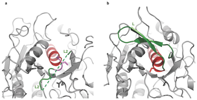
Active–site region of subtilisin and TPP II dimer. Corresponding structures of TPP II (a) and subtilisin Carlsberg (b) active–site regions following the color scheme shown in the aligned sequences in Supplementary Fig. 2. Note in particular, the differences in the end regions of the α–helices (in red) harboring the active–site serines, and the differences in the L and L2 loops (shown in green) where the L loop of subtilisin is a well–ordered stable structure and the L2 loop of TPP II is mostly disordered (regions not modelled are depicted by a dashed line).
The long loops of both TPPII and subtilisin, designated L2 and L respectively, are directly linked to the active–site serines. Although quite different in sequence, each loop is highly conserved within its respective family. Loop L (Gly202–Gly219 in subtilisin Carlsberg), has been found to be highly stable in all subtilisin structures determined to date: It makes a tight turn onto itself, forming many antiparallel β–sheet hydrogen bonds and is tethered down by hydrogen bonds established with several residues from other regions of the protein (Fig. 3b). In contrast, most of the L2 loop found in an isolated TPP II dimer is not well structured. This difference suggests that, in order to activate a dimer, loop L2 must undergo a conformational change, which leads to the removal of the three–residue segment from the substrate–binding cleft and allows the unwound segment harbouring the active–site serine to assume an α–helical conformation. As a consequence, a network of hydrogen bonds similar to that found in this region of subtilisin would be established and the active– site serine would be located in the appropriate position. This could occur during the assembly–dependent activation of TPP II mediated through the stacking of dimers to form holocomplexes, during which loop L2, acting as an activation switch, relocates and assumes a new conformation facilitated through interactions made with residues from an adjoining dimer.
Molecular structure of the TPP II holocomplex
In order to obtain a pseudo–atomic model of the TPP II holocomplex showing architectural details of the assembly and revealing the location of the active sites and the L2 loops within the spindle, the crystal structure of the TPP II dimer was docked into a density map of the TPP II spindle determined by cryo–EM (Fig. 4a–d) (see Supplementary Video 1). At ~ 14 Å resolution, this cryo–EM map has a higher resolution than the previously published map17, facilitating an accurate docking (Supplementary Fig. 3). The fit of the crystal structure of the dimers is very good throughout the entire EM map. Nevertheless, it is interesting to note that the correlation coefficients for the in–strand dimers range from 0.68 to 0.73, whereas the correlation coefficient for the end–of–strand dimers is slightly lower (0.62). This lower value can be attributed, in part, to a few unaccounted for densities in the EM map. In the monomers at the spindle ends, the hinge region (~Lys149–Leu180) located between the bowl and handle extends beyond the boundary of the EM–map (Fig. 4d). In addition, there is well–defined density located between the handle and body of the terminal dimers that is unaccounted for by the docked model. This density is located near the region of the missing loop “L3”, depicted by a dashed line in Figures 1c and 4d, suggesting that this is the location of the loop “L3”. The presence of this additional density, which is not visible in the in–strand dimers, suggests that the lower correlation coefficient for the terminal dimers is due to a genuine conformational difference. In fact, the end–of–strand dimers have a special role in stabilizing the quaternary structure of TPP II. They provide the only sites of reciprocal contacts between the two strands, a feature previously described as the double– clamp17. The contact area at each end is approximately 1750 Å2, which should be sufficient to favour the double–strand structure over other forms of the assembly.
Figure 4.

Hybrid model of the TPP II spindle. (a) Density map of the TPP II spindle obtained by cryo–EM at ~ 14 Å resolution. (b) The pseudo–atomic model of the TPP II spindle docked into the cryo–EM map. Dimers are depicted in monomer pairs colored red and orange, or dark blue and light blue. (c) Two dimers docked into the central part of the TPP II envelope. The color–coding for the dimers is the same as used for Figure 1: yellow, subtilisin domain (residues 1–522); red, active site residues (Asp44, His272, Ser462, Asn374); orange, insert (residues 75–266); green, central domain (residues 523–1098); blue, C–terminal domain (residues 1099–1354); the adjoining monomers are shown in a lighter shade of the same color scheme. (d) Close–up view of two dimer models docked into the cryo–EM map of the TPP II spindle at a terminal position. Arrow 1 labels the hinge region in the terminal monomer (residues 149–180) that extends beyond the boundary of the EM– map. Arrow 2 labels the additional density in the terminal dimers that may represent loop “L3”. Images produced with Chimera36.
In the cryo–EM density map of the holocomplex, there are relatively strong densities, at the intra–strand dimer–dimer contact regions near the active sites and where the L2 loops are located (Fig. 5), that are unaccounted for by the docked models. These densities are close to Ser462 and are likely to be sites for the relocation of loop L2 upon the assembly of dimers into strands. The conformational change required for its relocation to this site would bring loop L2 into close proximity to residues of the contacting dimer. Association with these residues could stabilize loop L2 in this new conformation and, thereby, enable the establishment of a hydrogen bond network that supports the active conformation of Ser462. To investigate this possibility, point mutants of selected residues in both loop L2 and the potential acceptor–region (which includes residues 603–610, Fig. 5c) were generated. TPP II mutated at the highly conserved residues L603E, L605E, and R610D or the conserved loop L2 residue K454E was found to be inactive, yielding strands but not spindles (Supplementary Table 2). This mutation data, together with the x–ray and cryo–EM structure data, supports the notion that – in the active spindle – loop L2 and residues 603– 610 are in close contact, establishing the hydrogen bond network required for a functional active site.
Figure 5.

Density at the dimer–dimer contact region and the relocation of loop L2. (a) Two docked dimers are shown in light and dark blue. In the lower dimer the subtilisin–like domain is shown in yellow. (b) Enlarged region of a, in addition, region 441–480 (helix– Ser462–L2) is shown in red. The box marks the slab containing the helix connected to the active–site Ser462 and L2. (c) Orthogonal view of boxed region in b. The black arrow shows the density unaccounted for by the model at the proposed relocation site of L2 (red) in the spindle. Location of residues in the adjacent dimer that were involved in mutation studies is highlighted in green. Images were produced with Chimera36.
Chamber system of TPP II
In addition to activation, the stacking of the TPP II dimers into strands also leads to the formation of a network of chambers, which is accessible via openings at both sides of the stacked handles (Fig. 6). At each dimer–dimer interface a suite of chambers (consisting of one antechamber connected to two adjacent catalytic chambers) is formed: By the reciprocal association of the dimers the active–site containing bowls are covered, which leads to the formation of the catalytic chambers and the joining of the antechamber halves. Each antechamber is connected through a T–joint to two foyers. The foyers are situated underneath the handles and are accessible from large openings on either side of a handle.
Figure 6.

Chamber system of TPP II and pathways to the active sites. (a) A segment of the pseudo–atomic model of a TPP II strand with two dimers highlighted in red/orange (dimer 1) and light blue/dark blue (dimer 2). Entrances to the foyers on either side of each handle are shown by yellow arrows. (b) Clipped view of a in which the handles have been removed to reveal the foyers “F”. Clipped regions shown in black. (c) Clipped view of a, past the section in b, revealing an antechamber (dotted white ellipse) and the partial views of the entrances to the catalytic chambers (“CC”). Pathways leading from the foyers to the antechamber are indicated by solid arrows; pathways leading to alternative antechambers are indicated by dashed arrows. (d) View in c rotated slightly about the spindle axis to show a complete catalytic chamber entrance (white arrow). (e) View of a rotated 90° about the spindle axis. Entrances to the foyers on either side of each handle are shown by yellow arrows. (f) Cross–section of e with a clipping plane nearly parallel to the spindle axis. “F”: foyer entrance, “AC”: antechamber, “CC”: catalytic chamber. (g) Surface model of a single strand (same region as in e and f) low–pass filtered to 12 Å resolution showing both the external surface (in transparent mesh colored as in e and internal surface (in solid gray) to aid visualization of the chamber system. The S462 residues are shown as red spheres. (h) Schematic layout of TPP II chambers. “T”: T–joint, “H”: Handle, “H–H”: represents the contact of two handles that form the outer half of the T–joint. Active sites are represented as red dots within catalytic chambers in the plane of the figure and as pale red dots for the catalytic chambers closest to the viewer (outlined by white dashed lines). Black arrows show multiple pathways to reach the active sites; black dashed line denotes route to the catalytic chamber closest to the viewer.
The schematic diagram in Figure 6h depicts the chamber topology and the multiple routes for substrate access to the active sites. To reach the active sites inside a given suite of chambers, substrates can enter one of two neighbouring foyers through the large openings (~23 × 37 Å) at either side of each of the two adjacent handles, and pass through either opening (~22 × 20 Å) of a T–joint that leads to the antechamber entrance (~32 × 15 Å) (Supplementary Fig. 4). From the openings (~32 × 15 Å) at the far corners of the antechamber, substrates can enter either one of two catalytic chambers, each of which contains an active site at its far end. The route from the entry sites via the network of chambers to the active sites is a long one: Any substrate to be degraded by TPP II must diffuse over a distance of at least 120 Å to reach an active site. However, this is counterbalanced by the presence of multiple pathways to the active sites.
DISCUSSION
Assembly-dependent activation mechanism
The data presented suggest a model for the assembly–dependent activation of TPP II in which loop L2 plays a key role as an activation–switch (Fig. 7): TPP II dimers are inactive since the active–site serine Ser462 –which is directly linked to loop L2– is displaced. At the same time a three–residue segment of L2 is bound to the substrate–binding cleft, which precludes substrate binding to the cleft and thereby provides an autoinhibitory mechanism. As the dimers stack to form strands, the L2 loop is repositioned in such a way that new interactions between residues of loop L2 and residues along the roof of the catalytic chamber are formed. Concomitantly, the active–site serines are repositioned to proteolytically active conformations and the three–residue segments of the L2 loops are removed from the substrate binding clefts. Simultaneously the internal chamber system is established. Thus, the priming of the active sites is coupled to their sequestration from the bulk environment into chambers. This mechanism is fundamentally different from the activation mechanism of TPP I, a monomeric (~ 61 kDa) peptidase of the subtilisin type, which is synthesized as a zymogen favouring a non–optimal active–site geometry30.
Figure 7.

Schematic diagram of the proposed assembly–dependent activation mechanism. In the inactive TPP II dimers (left), the L2 loops (red) are flexible, but a three–residue segment of these loops occupies the substrate–binding clefts. The active–site serines, Ser462 (red “S”), are coupled to the L2 loops and are displaced away from the other members of the catalytic triads in the inactive dimers. Upon association of the dimers (right), the catalytic chambers (CC), which enclose the active sites, are formed at the dimer–dimer interface. At the same time the L2 loops (green) interact with the chamber–roof residues of an adjacent dimer leading to accessible substrate–binding clefts and the relocation of the active–site serines (green ”S”) to a catalytically active position.
Functional design of the TPP II structure
TPP II has been reported to degrade peptides larger than 15 amino acids7,31, and the openings in the structure of the holocomplex permit the passage of large peptides while excluding folded proteins of any size. Limitation of proteolytic products to tripeptides is achieved by tailoring the size of the substrate–binding cleft: The two negatively charged residues Glu312 and Glu343 that are blocking position P4 limit the number of residues that can be accommodated in the binding cleft and thus create a molecular ruler. At the same time they orient substrates so that the tripeptides are removed exclusively from the N– termini. This is a recurrent structural principle among aminopeptidases and the two glutamate residues appear to form the double–Glu motif that has emerged as the prevailing motif for imparting aminopeptidase activity on peptidases, such as Dipeptidylpeptidase IV22, Aminopeptidase N32, and Aminopeptidase F123. Among tripeptidyl peptidases, this motif has recently been described in prolyl tripeptidyl aminopeptidase from Porphyromonas gingivalis24,25. Based on homology to this peptidase, the double–Glu motif had been suggested to be present in TPP II33.
What distinguishes TPP II from other aminopeptidases is the linear arrangement of subunits and the very large subunit number. The multimeric spindle structure may result from the need to stabilize the holo–complex in a state of high specific activity via interaction of the two intertwined strands17. The corollary of this form of assembly is the massive local concentration of active sites and the existence of multiple interconnected pathways to the active sites, which may facilitate substrate access.
The compartmentalization of active sites is a hallmark of giant proteases as well as of most ATP–dependent proteases including the proteasome. In tricorn protease the active site is buried in a chamber inside a monomer, accessible via “Velcro”–like propeller domains; this architectural principle provides a mechanism for substrate discrimination by size exclusion4. In TPP II, the proteolytic chambers are formed when dimers assemble into tetramers or longer strands, and assembly is a prerequisite for the priming of the active sites. This is reminiscent of the proteasome, where the assembly of two half–proteasomes and the concomitant formation of the central proteolytic chamber triggers the switch for the autocatalytic removal of the propeptides, and thus the active site is formed34. In addition to compartmentalization of the active sites and to granting high activity at maximum stability18 we envisage the TPP II holocomplex, with multiple active sites along its strands and forming an extensive network of channels and chambers, to act like a ‘molecular sponge’ accumulating peptides but excluding folded proteins. This property provides protection from inadvertent proteolysis and a strong relative enrichment of substrates promoting enzymatic efficiency. Such enrichment of peptides (many of which are short–lived if free in the cytosol) inside the network of chambers – together with the presence of multiple active sites – should greatly enhance the efficiency of peptide processing and might be the reason for the low copy number of TPP II spindles in eukaryotic cells.
Supplementary Material
Acknowledgments
Diffraction data sets for the structure determination were collected at Beamline 8.2.2, Advanced Light Source, Lawrence Berkeley National Laboratory. We would like to thank Corie Ralston and her beamline staff for their assistance. We thank Dr. Andreas Sonnen for the calculation of the contact areas. This work is supported by funding from the Deutsche Forschungsgemeinschaft (B.R.), the National Institutes of Health (B.K.J.), and by the US Department of Energy.
Footnotes
AUTHOR CONTRIBUTIONS
W.B. and B.K.J. conceived the project. X–ray crystallography work, from purification to final structure, was conducted by C.K.C. under the guidance of B.K.J.; P.W. was involved in data collection and processing and P.Z. in initial processing of data; G.S. and J.P. were involved with initial purification and crystallization trials; EM structural studies were done by B.R.; A.S. and J.P. performed mutation and functional studies. Manuscript was written by C.K.C., B.R., J.P., B.K.J., and W.B. All authors read and edited the manuscript.
Accession codes. Atomic coordinates and structure factors for the reported crystal structure have been deposited with the Protein Data Bank under accession code: 3LXU. The cryo-EM density map has been deposited to the EM Data Bank with accession code EMD-1732.
Note: Supplementary Information is available on the Nature Structural & Molecular Biology website.
References
- 1.Yao T, Cohen RE. Giant proteases: beyond the proteasome. Curr Biol. 1999;9:R551–R553. doi: 10.1016/s0960-9822(99)80352-2. [DOI] [PubMed] [Google Scholar]
- 2.Tamura T, Tamura N, Cejka Z, Hegerl R, Lottspeich F, Baumeister W. Tricorn protease––the core of a modular proteolytic system. Science. 1996;274:1385–1389. doi: 10.1126/science.274.5291.1385. [DOI] [PubMed] [Google Scholar]
- 3.Tamura N, Lottspeich F, Baumeister W, Tamura T. The role of tricorn protease and its aminopeptidase–interacting factors in cellular protein degradation. Cell. 1998;95:637–648. doi: 10.1016/s0092-8674(00)81634-7. [DOI] [PubMed] [Google Scholar]
- 4.Brandstetter H, Kim J, Groll M, Huber R. Crystal structure of the tricorn protease reveals a protein disassembly line. Nature. 2001;414:466–470. doi: 10.1038/35106609. [DOI] [PubMed] [Google Scholar]
- 5.Walz J, Tamura T, Tamura N, Grimm R, Baumeister W. Tricorn protease exists as an icosahedral supermolecule in vivo. Mol Cell. 1997;1:59–65. doi: 10.1016/s1097-2765(00)80007-6. [DOI] [PubMed] [Google Scholar]
- 6.Tomkinson B. Tripeptidyl peptidases: enzymes that count. Trends Biochem Sci. 1999;24:355–359. doi: 10.1016/s0968-0004(99)01435-8. [DOI] [PubMed] [Google Scholar]
- 7.Reits E, et al. A major role for TPP II in trimming proteasomal degradation products for MHC class I antigen presentation. Immunity. 2004;20:495–506. doi: 10.1016/s1074-7613(04)00074-3. [DOI] [PubMed] [Google Scholar]
- 8.York IA, Bhutani N, Zendzian S, Goldberg AL, Rock KL. Tripeptidyl peptidase II (TPPII) is the major peptidase needed to trim long antigenic precursors, but is not required for most MHC class I antigen presentation. J Immunol. 2006;177:1434–1443. doi: 10.4049/jimmunol.177.3.1434. [DOI] [PubMed] [Google Scholar]
- 9.Firat E, et al. Analysis of direct and cross–presentation of antigens in TPPII knockout mice. J Immunol. 2007;179:8137–8145. doi: 10.4049/jimmunol.179.12.8137. [DOI] [PubMed] [Google Scholar]
- 10.Van Endert P. Role of tripeptidyl peptidase II in MHC class I antigen processing–the end of controversies? Eur J Immunol. 2008;38:609–613. doi: 10.1002/eji.200838181. [DOI] [PubMed] [Google Scholar]
- 11.Kawahara M, et al. Analysis of the role of tripeptidyl peptidase II in MHC class I antigen presentation in vivo. J Immunol. 2009;183:6069–6077. doi: 10.4049/jimmunol.0803564. [DOI] [PMC free article] [PubMed] [Google Scholar]
- 12.Hasselgren PO. Molecular regulation of muscle cachexia: it may be more than the proteasome. Biochem Biophys Res Commun. 2002;290:1–10. doi: 10.1006/bbrc.2001.5849. [DOI] [PubMed] [Google Scholar]
- 13.Stavropoulou V, Vasquez V, Cereser B, Freda E, Masucci MG. TPPII promotes genetic instability by allowing the escape from apoptosis of cells with activated mitotic checkpoints. Biochem Biophys Res Commun. 2006;346:415–425. doi: 10.1016/j.bbrc.2006.05.141. [DOI] [PubMed] [Google Scholar]
- 14.Huai J, et al. Activation of cellular death programs associated with immunosenescence– like phenotype in TPPII knockout mice. Proc Natl Acad Sci USA. 2008;105:5177–5182. doi: 10.1073/pnas.0801413105. [DOI] [PMC free article] [PubMed] [Google Scholar]
- 15.Rose C, et al. Characterization and inhibition of a cholecystokinin–inactivating serine peptidase. Nature. 1996;380:403–409. doi: 10.1038/380403a0. [DOI] [PubMed] [Google Scholar]
- 16.McKay RM, McKay JP, Suh JM, Avery L, Graff JM. Tripeptidyl peptidase II promotes fat formation in a conserved fashion. EMBO J. 2007;8:1183–1189. doi: 10.1038/sj.embor.7401086. [DOI] [PMC free article] [PubMed] [Google Scholar]
- 17.Rockel B, et al. Molecular architecture and assembly of Drosophila tripeptidyl peptidase II. Proc Natl Acad Sci USA. 2005;102:10135–10140. doi: 10.1073/pnas.0504569102. [DOI] [PMC free article] [PubMed] [Google Scholar]
- 18.Seyit G, Rockel B, Baumeister W, Peters J. Size matters for the tripeptidase II complex from Drosophila: the 6–MDa spindle form stabilizes the activated state. J Biol Chem. 2006;281:25723–25733. doi: 10.1074/jbc.M602722200. [DOI] [PubMed] [Google Scholar]
- 19.Steitz TA, Shulman RG. Crystallographic and NMR studies of the serine proteases. Annu Rev Biophys Bioeng. 1982;11:419–444. doi: 10.1146/annurev.bb.11.060182.002223. [DOI] [PubMed] [Google Scholar]
- 20.Bode W, Papamokos E, Musil D, Seemueller U, Fritz H. Refined 1.2 A crystal structure of the complex formed between subtilisin Carlsberg and the inhibitor eglin c. Molecular structure of eglin and its detailed interaction with subtilisin. EMBO J. 1986;5:813–818. doi: 10.1002/j.1460-2075.1986.tb04286.x. [DOI] [PMC free article] [PubMed] [Google Scholar]
- 21.Schechter I, Berger A. On the size of the active site in proteases. I. Papain. Biochem Biophys Res Commun. 1967;27:157–162. doi: 10.1016/s0006-291x(67)80055-x. [DOI] [PubMed] [Google Scholar]
- 22.Engel M, et al. The crystal structure of dipeptidyl peptidase IV (CD26) reveals its functional regulation and enzymatic mechanism. Proc Natl Acad Sci USA. 2003;100:5063–5068. doi: 10.1073/pnas.0230620100. [DOI] [PMC free article] [PubMed] [Google Scholar]
- 23.Goettig P, et al. X–ray snapshots of peptide processing in mutants of tricorn–interacting factor F1 from Thermoplasma. J Biol Chem. 2005;280:33387–33396. doi: 10.1074/jbc.M505030200. [DOI] [PubMed] [Google Scholar]
- 24.Ito K, et al. Crystal structure and mechanism of tripeptidyl activity of prolyl tripeptidyl aminopeptidase from Porphyromonas gingivalis. J Mol Biol. 2006;362:228–240. doi: 10.1016/j.jmb.2006.06.083. [DOI] [PubMed] [Google Scholar]
- 25.Xu Y, et al. Novel inhibitor for prolyl tripeptidyl aminopeptidase from Porphyromonas gingivalis and details of substrate–recognition mechanism. J Mol Biol. 2008;375:708–719. doi: 10.1016/j.jmb.2007.09.077. [DOI] [PubMed] [Google Scholar]
- 26.Rao SN, Singh UC, Bash PA, Kollman PA. Free energy perturbation calculations on binding and catalysis after mutating Asn 155 in subtilisin. Nature. 1987;328:551–554. doi: 10.1038/328551a0. [DOI] [PubMed] [Google Scholar]
- 27.Bryan P, Pantoliano MW, Quill SG, Hsiao HY, Poulos T. Site–directed mutagenesis and the role of the oxyanion hole in subtilisin. Proc Natl Acad Sci USA. 1986;83:3743–3745. doi: 10.1073/pnas.83.11.3743. [DOI] [PMC free article] [PubMed] [Google Scholar]
- 28.Wells JA, Cunningham BC, Graycar TP, Estell DA. Importance of hydrogen–bond formation in stabilizing the transition state of subtilisin. Philos Trans R Soc London Ser A. 1986;317:415–423. [Google Scholar]
- 29.Carter P, Wells JA. Functional interaction among catalytic residues in subtilisin BPN’. Proteins. 1990;7:335–342. doi: 10.1002/prot.340070405. [DOI] [PubMed] [Google Scholar]
- 30.Guhaniyogi J, Sohar I, Das K, Stock AM, Lobel P. Crystal structure and autoactivation pathway of the precursor form of human tripeptidyl–peptidase 1, the enzyme deficient in late infantile ceroid lipofuscinosis. J Biol Chem. 2009;284:3985–3997. doi: 10.1074/jbc.M806943200. [DOI] [PMC free article] [PubMed] [Google Scholar]
- 31.Geier E, et al. A giant protease with potential to substitute for some functions of the proteasome. Science. 1999;283:978–981. doi: 10.1126/science.283.5404.978. [DOI] [PubMed] [Google Scholar]
- 32.Ito K, et al. Crystal structure of aminopeptidase N (Proteobacteria Alanyl Aminopeptidase) from Escherichia coli and conformational change of methionine 260 involved in substrate recognition. J Biol Chem. 2006;281:33664–33676. doi: 10.1074/jbc.M605203200. [DOI] [PubMed] [Google Scholar]
- 33.Lindås A-C, Eriksson S, Jozsa E, Tomkinson B. Investigation of a role for Glu– 305 and Glu–331 in substrate binding of tripeptidyl–peptidase II. Biochim Biophys Acta. 2008;1784:1899–1907. doi: 10.1016/j.bbapap.2008.08.017. [DOI] [PubMed] [Google Scholar]
- 34.Löwe J, et al. Crystal structure of the 20S proteasome from the archaeon T. acidophilum at 3.4 A resolution. Science. 1995;268:533–539. doi: 10.1126/science.7725097. [DOI] [PubMed] [Google Scholar]
- 35.DeLano WL. The PyMOL Molecular Graphics System. DeLano Scientific; Palo Alto, CA, USA: 2002. http://www.pymol.org. [Google Scholar]
- 36.Pettersen EF, et al. UCSF Chimera–Avisualization system for exploratory research and analysis. J Comput Chem. 2004;25:1605–1612. doi: 10.1002/jcc.20084. [DOI] [PubMed] [Google Scholar]
- 37.Otwinowski Z, Minor W. Processing of X–ray diffraction data collected in oscillation mode. In: Carter CW Jr, Sweet RM, editors. Methods in Enzymology. Vol. 276. Academic Press; New York: 1997. pp. 307–326. [DOI] [PubMed] [Google Scholar]
- 38.Adams PD, et al. PHENIX: building new software for automated crystallographic structure determination. Acta Cryst. 2002;D58:1948–1954. doi: 10.1107/s0907444902016657. [DOI] [PubMed] [Google Scholar]
- 39.Emsley P, Cowtan K. Coot: model–building tools for molecular graphics. Acta Cryst. 2004;D60:2126–2132. doi: 10.1107/S0907444904019158. [DOI] [PubMed] [Google Scholar]
- 40.Laskowski RA, MacArthur MW, Moss DS, Thornton JM. PROCHECK – A program to check the stereochemical quality of protein structures. J Appl Crystallogr. 1993;26:283–291. [Google Scholar]
- 41.Ludtke SJ, Baldwin PR, Chiu W. EMAN: Semiautomated software for high– resolution single–particle reconstructions. J Struct Biol. 1999;128:82–97. doi: 10.1006/jsbi.1999.4174. [DOI] [PubMed] [Google Scholar]
- 42.Wriggers W, Milligan RA, McCammon JA. Situs: A package for docking crystal structures into low–resolution maps from electron microscopy. J Struct Biol. 1999;125:185–195. doi: 10.1006/jsbi.1998.4080. [DOI] [PubMed] [Google Scholar]
Associated Data
This section collects any data citations, data availability statements, or supplementary materials included in this article.