Abstract
A new technical approach to breast-tumor detection is proposed. The technique is based on fluorescence x-ray analysis, and can identify a miniature malignant tumor within the breast. The primary beam intensity needed in fluorescence x-ray analysis is on a lower order of magnitude than that used in mammography. Thus, the newly-proposed technique would enable detection of a still tiny breast cancer while dramatically lowering the radiation dose. Field-emission x-ray sources might be a key for translating this concept into a medical technique.
Keywords: X-ray, field-emission, fluorescence analysis, breast cancer
Abstract
Ein neues technisches Verfahren zum Nachweis von Brustkrebs wird vorgeschlagen. Das Verfahren beruht auf Röntgen-Fluoreszenz-Analyse und könnte sehr kleine bösartige Tumore in der Brust nachweisen. Bei der Röntgen-Fluoreszenz-Analyse ist die Intensität des Primärstrahles niedriger als bei der Mammographie. Das vorgeschlagenen Verfahren würde es bei starker Reduktion der Strahlendosis ermöglichen, sehr kleine Tumore in der Brust nachzuweisen. Bei den Röntgenstrahlen könnte das Feldemissions-Verfahren eingesetzt werden, um das Verfahren in der Medizintechnik einzuführen.
Introduction
Among the prevailing therapies for breast cancer, surgery is the most promising. The ultimate demand on the breast cancer surgery is that it should be minimally invasive.
To address this issue, the cancer must be detected at its earliest and most treatable stage. It is also indispensable to locate the cancerous lump, in as painless a manner as possible. If these requirements are fulfilled, the cancer can be removed minimally invasively by surgery. The most common technique for breast cancer detection is today mammography. Unfortunately, mammography involves a series of difficulties associated with simple x-ray imaging, typical of which is the detectable tumor dimension larger than several mm in diameter. A technique to detect breast cancer at a higher sensitivity has thus been much awaited within the medical community and women at risk. Here we propose a physical concept that may evolve into a sensitive breast cancer detection technique in future.
Difficulties in mammography
In mammography, the breast is exposed to soft or semi-soft x-ray beams generated by a thermionic x-ray source, and the image formed by transmitted x-rays is visually inspected. Underlying this technique is the fact that the calcium (Ca) present in milk ducts migrates to cancerous tissues to accumulate therein (so-called “calcification”). Since the x-ray absorption coefficient of Ca is higher than that of soft tissues, the cancer is distinguished from normal tissues on the detector, usually a photographic plate. In practical diagnosis, the smallest tumor that a mammogram can detect measure 8–10 mm in diameter. Hundreds of thousands of malignant cells are involved in such a mm-size cancer, some of which might have already escaped to the rest of the body through the bloodstream. If the cancer-detection sensitivity is improved by a factor of ten, then surgery could eliminate cancerous tissues while doing little damage to the breast. Also, mammography is inescapable from a drawback intrinsic to visual diagnosis. The following is an example.
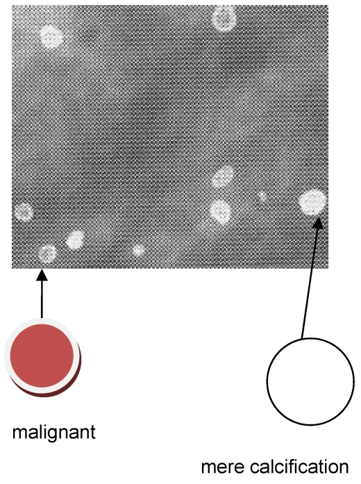
Ca and its compounds are always present in milk ducts. Mammography is unable to distinguish these mere calcifications from a microscopic cancerous lump. See, for example, Figure 1 (Fig. 1). This is a mammogram of a female breast, revealing calcified tiny tissues (white dots). An appreciable number of the calcified dots are malignant, and prone to spread into the immediate vicinity. This mammogram does not identify which calcified dot is malignant. What’s worse, the breast cancer in the younger generation does not always entail the calcification. Mammography is powerless to detect such a non-calcified cancer.
Figure 1. A mammogram of female breast, revealing micro-calcifications (white dots) [6], reproduced with permission.
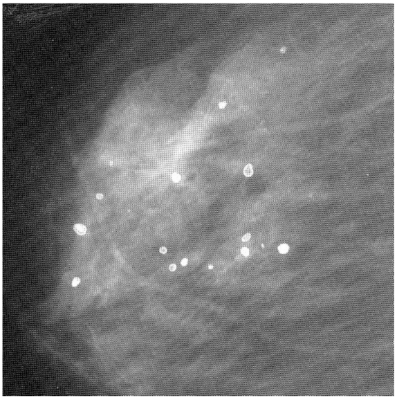
In mammography, the intensity distribution of transmitted x-ray beams is converted to image contrast on the photographic plate. Mammograms are thus no more than breast shadowgraphs, often leading to erroneous diagnosis. If malignant tumor were color-marked on the monitor, malignant and non-malignant dots could be precisely differentiated and hence the accuracy of breast-cancer diagnosis could be dramatically improved. We consider that element mapping coupled with x-ray fluorescence analysis (XRF) may well make this possible (see below).
Principle of the technique proposed
XRF
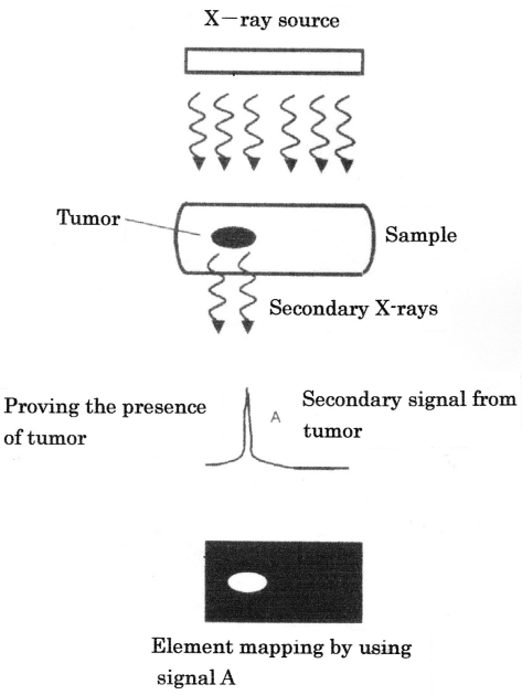
When a condensed-matter sample absorbs x-rays, the elements composing the sample emit x-rays through electronic transition. The secondary x-rays so emitted, referred to as “fluorescence x-rays,” are comprised of a family of monochromatic signals directly related to the electronic structures of the elements. Figure 2 (Fig. 2) illustrates our proposal to detect by XRF a malignant tumor growing in the breast. When the breast receives primary x-rays, the constituents of the breast emit secondary x-rays with wavelengths characteristic of the respective constituents. By wavelength analysis of secondary x-rays, the cancer-composing elements could be identified. Also, XRF provides visual information on how elements are distributed throughout the sample (so-called “element mapping”). We thus consider that a tiny breast cancer could be pinpointed by element mapping (Figure 3 (Fig. 3)). For this, however, we need a “test agent”, which preferentially accumulates in the malignant area (see later).
Figure 2. Principle of XRF of biological tissues involving a malignant tumor.
Figure 3. Detecting malignant tumor by elemental mapping (illustration).
Field emission x-ray source
Commonly, fluorescence x-ray spectra involve background signals or noises. One way to minimize noise is to use monochromatic x-rays as the primary beam. Presently, however, the primary beam in XRF is not monochromatic but continuous (white), presumably because the generation of monochromatic x-rays is usually not easy with thermionic emission (TE) x-ray sources. In the tumor detection by XRF, the smaller the tumor, the weaker the secondary signals would be. To detect an early-stage tumor, therefore, noise signals must be minimal.
When a non-insulating solid is put in a negative electric field as high as 107 V/cm, an appreciable number of electrons at the Fermi level tunnel out through the inclined surface-potential barrier. This type of electron emission has been termed “field-electron emission” (FE) [1].
To attain the field strength required for FE, the electron source has to be sharpened into a “tip” with nanometric dimensions; carbon nanotubes (CNTs) [2] and carbon nanofibers (CNFs) [3] are ideal FE electron sources [4], [5].
The FE process is exponentially affected by the chemical and morphological states of the electron-emitting area [6], resulting in instability of emitted currents in non-ultrahigh vacuum (non-UHV) ambiences, where the interaction is unavoidable between the electron-emitting surface and residual gases. For stable emitter-operation in FE mode, therefore, the gun chamber has to be pumped down to UHV.
Preliminary information
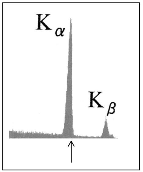
It was noted above that the primary beam in XRF must be monochromatic, in order to increase the S/N ratio. Figure 4 (Fig. 4) shows the spectrum of x-rays generated by striking a molybdenum target with 50-keV FE electrons. It is seen that the x-rays were perfectly characteristic, with no continuous signal overlap. X-rays emitted from other metals bombarded with FE electrons were also ideally characteristic. As is generally known, characteristic signals can be brought into a single signal with a filter, usually a metal film.
Figure 4. Spectrum of x-rays radiated from a molybdenum target bombarded with 50-keV FE electrons. The arrow indicates the Kα position at 17.4 keV.
Prospects for biological application of XRF
For a tumor to be imaged by mammography, it must absorb photons at more than 1010/sec, which are so abundant as to induce an overdose of radiation. In particular, soft x-rays used in mammography strongly interact with biological tissues, thereby damaging the surrounding normal areas. Thus, a crucial demand for a next-generation breast cancer detection technique is the ability to detect a miniature tumor with high precision while lowering the radiation dose. It is also pivotal to pinpoint the location of the tumor (see section “Principle of the technique proposed”). This tumor spotting would help doctors determine the nucleation site of the tumor. Mammography is equipped with neither of these functions.
Most breast cancers begin in milk ducts. Figure 5 (Fig. 5) shows schematically the growth process of breast cancer nucleated in milk duct. Stage 0 (Figure 5c (Fig. 5)) is barely detectable by mammography. The “atypical ductal hyperplasia” (ADH) in Figure 5b (Fig. 5) is thus a pre-cancerous state, the detection of which would open a new era in breast cancer therapy. ADH is supposed to be of micrometric dimensions, and hence totally undetectable by conventional mammography. This is why devising a breast cancer detection technique far superior in sensitivity to mammography is a matter of urgency.
Figure 5. Development of breast cancer within milk duct. (a) Normal, (b) pre-cancerous, (c) stage 0 and (d) stage 1. (b) corresponds to a “typical ductal hyperplasia” (ADH) [20], reproduced with permission.
In our view, XRF might satisfy the above demands. The detection limit of XRF is less than 10 ppm, which is sufficient to catch a cancerous lump of micrometric dimensions. As stated already, the element mapping based on XRF offers visual information on the element distribution throughout a non-biological sample. If this mapping technique were applicable to breast cancer detection, the growth site of a micrometric cancer could be pinpointed accurately and promptly. For this, effective test agents are indispensable.
The “test agent” refers to a chemical compound that accumulates in a cancerous region. The most promising candidates are currently nanoparticles of ferromagnetic metal oxides. Magnetite (Fe3O4) nanoparticles conjugated with an antibody fragment, for instance, selectively bind to cancerous cells, irrespective of cancer species [7]. Magnetite itself is non-toxic, and its fine particles are excreted through a physiological process.
Fluid agents could be injected into milk ducts through the nipple with the aid of a syringe and a local anesthetic. Since magnetite nanoparticles can be dispersed in an organic solvent (so-called “magnetic fluids”), they will be readily supplied to the cancerous region in the above-described manner. Magnetite nanoparticles might thus be a practical, as well as an effective, test agent for breast cancer detection. It is emphasized that the high affinity of magnetite nanoparticles to cancerous cells has been applied for hyperthermia of mouse solid cancers including breast cancer [7].
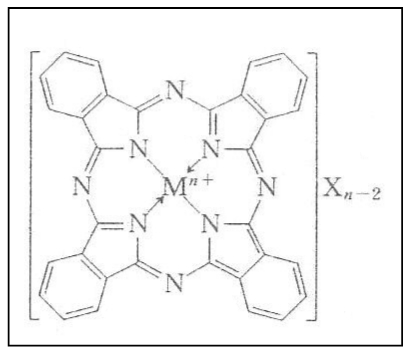
A matter of concern is that secondary x-rays emitted from Fe is so low in energy (6.4 keV for Kα) that they may fade away within a bulky human breast due to absorption. Like magnetite, phthalocyanine molecules aggregate in cancerous tissues. This material accommodates a metal atom at its center, independently of whether the metal is ionic or covalent in bonding character (cf. Figure 6 (Fig. 6)). If the metal atom is of a heavy metal, the fluorescence x-rays that it emits would be high enough in energy to get out of the breast. We have been informed that phthalocianine is actually being used for laser therapy of some cancers. Unfortunately, phthalocianine molecules are so fragile that they decompose into fragments through chemical interactions with air. Synthesizing stable derivatives of phthalocianine is thus solicited.
Figure 6. Molecular structure of phthalocianine.
Instrumentation
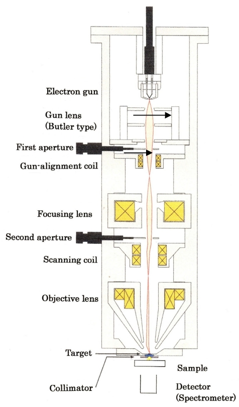
Figure 7 (Fig. 7) illustrates the cross-sectional view of the prototypical XRF machine that we propose. What follows is its outline.
Figure 7. Cross-sectional illustration of the prototype XRF machine. Emitter replacement is done while maintaining a high vacuum in the gun chamber.
1) Emitter: A key element in this devise is the electron emitter. For element mapping, a fine electron beam has to be scanned on the target.
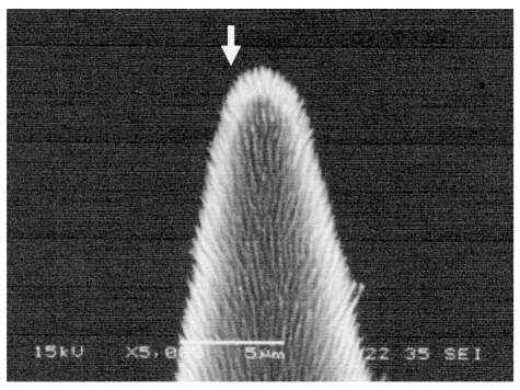
Well-suited for this purpose would be the “CNTs-on-tip”emitter (Figure 8 (Fig. 8)) [8], [9], [10]. The total electron current that this type of emitter provides amounts to ~0.1 mA at an extracting voltage lower than 10 kV [11]. In addition, more than 90% of the electrons extracted from a CNTs-on-tip emitter can be guided to the target by properly designing the focusing system [12]. An electron current of this level is high enough for a prototypical machine. In view of the average diameter of 10 µm, there will be no need to strongly focus the electron beams.
Figure 8. CNFs-on-tip emitter (SEM image). Electron emission takes place at the tip end (arrow-indicated).
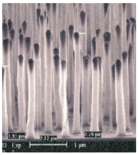
In an element mapping system for clinical use, the FE gun must provide an electron beam on the order of mA. The CNTs-on-tip emitter does not fulfil this requirement. Our prospect is that the “aligned CNT emitter” [13], which is comprised of CNTs vertically aligned on an Si substrate, would be best suited to clinical use. Figure 9 (Fig. 9) shows a typical example of aligned CNTs. A single CNT in such a CNT array emits an electron current as large as 100 µA through self-annealing [13]. If the substrate surface is concave, electrons coming from CNTs are converged automatically [14]. When coupled with external focusing, this “self-focusing” would lead to a fine focusing of electron beams without losing the original current intensity. The surface-processing technique to grow CNTs on a concave substrate has therefore to be established prior to moving into the second stage of developing a clinical instrument.
Figure 9. CNTs vertically aligned on a Si wafer.
2) Pressure in gun chamber: 10-7 Pa region. Thanks to recent progress in UHV technology, there is no difficulty in evacuating the gun chamber into this pressure region.
Illustrated in Figure 7 (Fig. 7) is only one example of devices in line with our aim. Other designs will also be available for focusing an electron beam from multiple CNT tips (see, for example, [15]).
Ultimate goal
The device in Figure 7 (Fig. 7) is for fundamental research on samples which are small animals such as mice. Based on the information obtained by this device, the final decision will be made as to whether or not we should process to construct a clinical XRF. If we go forward, we should take the followings into consideration.
Geometrically, the human breast is three-dimensional even if compressed mechanically. Strictly speaking, therefore, the tumor’s three-dimensional location in the breast must be known prior to treatment. For simple imaging, the “digital volume tomography”(DVT) outlined in the Appendix [16], [17] would fit this purpose. At the present time, we are not convinced that DVT will evolve to analytical devices, but establishing fluorescence x-ray DVT would be prerequisite to apply our concept clinically.
When a solid in a superconducting state absorbs a photon, it loses superconductivity because the energy of incident photons is converted into thermal energy. The “transition-edge sensor” (TES) [18] is based on this physical principle. A striking fact is that TES is able to detect “one photon” as the function of photon energy.
Since the energy of incident photons is intrinsic to the electronic structure of their source, TES allows one to identify the source material with only one photon. To map the element distribution on the photon source, TES sensors have to be integrated on a large scale. Such a TES array has already been assembled, and actually installed in a scanning electron microscope (SEM) for mapping the element distribution on semiconductor chip surfaces [19]. The energy resolution of this SEM-TES system is about fifty times higher than that of conventional SEM-EDX systems. To the authors’ knowledge, no attempt has been made to clinically apply TES, but in light of serious concern over medical issues, developing medical TES systems will be an urgent issue in the foreseeable distant future. We are convinced that the application of integrated TES to fluorescence DVT will open a new frontier in breast cancer diagnosis.
Appendix
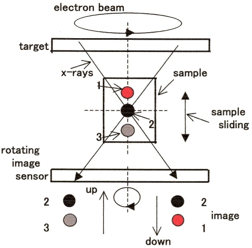
One of the most common techniques available to visualize the interior of bulky biological samples is x-ray CT. In conventional CT, the x-ray source is rotated around the sample, but this is not allowed for XRF. DVT is a viable alternative to CT (see DVT principle outlined in Figure 10 (Fig. 10). In brief, the x-rays incident on the intersection of the horizontal and vertical axes, or the imaging position, yield a clear image. In this drawing, the black circle 1 is located at the pinpoint of intersection and hence sharply imaged on the detector. When sliding the sample vertically, the image 1 is followed by the image 3 (gray) or 2 (red) on the detector, depending on the sliding direction. In DVT, the image is recorded on a flat panel detector (FPD). If the FPD is replaced by an x-ray spectrometer rotatable around the vertical axis, the in-depth distribution of constituent elements could be profiled.
Figure 10. Principle of DVT. The focused electron beam and the image sensor are coaxially rotated in the opposite directions at the same velocity.
List of abbreviations
ADH: atypical ductal hyperplasia
Ca: calcium
CNFs: carbon nanofibers
CNTs: carbon nanotubes
DVT: digital volume tomography
FE: field-electron emission
Fe3O4: magnetite
SEM: scanning electron microscope
TE: thermionic electron emission
TES: transition-edge sensor
UHV: ultrahigh vacuum
XRF: x-ray fluorescence analysis
Notes
Conflicts of interest
The authors declare no competing interests.
Acknowledgments
We are much indebted to Y. Sakai, JEOL, for fruitful discussions and suggestions. We are also grateful to T. Tohru for informing us of the medical importance of phthalocyanine.
References
- 1.Fowler RH, Nordheim LW. Electron emission in intense electric fields. Proc R Soc Lond A Math Phys Sci. 1928;119(781):173–181. doi: 10.1098/rspa.1928.0091. Available from: http://dx.doi.org/10.1098/rspa.1928.0091. [DOI] [Google Scholar]
- 2.Iijima S. Herical microtubules of graphitic carbon. Nature. 1991;354:56–58. doi: 10.1038/354056a0. Available from: http://dx.doi.org/10.1038/354056a0. [DOI] [Google Scholar]
- 3.Endo M, Kroto HW. Formation of carbon nanofibres. J Phys Chem. 1992;96(17):6941–6944. doi: 10.1021/j100196a017. Available from: http://dx.doi.org/10.1021/j100196a017. [DOI] [Google Scholar]
- 4.de Jonge N, Bonard JM. Carbon nanotube electron sources and applications. Philos Trans R Soc Lond A. 2004;362(1823):2239–2266. doi: 10.1098/rsta.2004.1438. Available from: http://dx.doi.org/10.1098/rsta.2004.1438. [DOI] [PubMed] [Google Scholar]
- 5.Kita S, Watanabe Y, Ogawa A, Ogura K, Sakai Y, Matsumoto Y, Isokane Y, Okuyama F, Nakazato T, Otsuka T. Field-emission-type x-ray source using carbon-nanofibers. J Appl Phys. 2008;103(6):064505–064511. doi: 10.1063/1.2894730. Available from: http://dx.doi.org/10.1063/1.2894730. [DOI] [Google Scholar]
- 6.Endou T, editor. Mammography Guideline. Tokyo: Igaku Shoin; 2004. [Google Scholar]
- 7.Shinkai M, Le B, Honda H, Yoshikawa K, Shimizu K, Saga S, Wakabayashi T, Yoshida J, Kobayashi T. Targeting hyperthermia for renal cell carcinoma using human MN antigen-specific magnetolisomes. Jpn J Cancer Res. 2001;92(10):1138–1145. doi: 10.1111/j.1349-7006.2001.tb01070.x. [DOI] [PMC free article] [PubMed] [Google Scholar]
- 8.Haga A, Senda S, Sakai Y, Kita S, Okuyama F. A miniature x-ray tube. Appl Phys Lett. 2004;84(12):2208–2210. doi: 10.1063/1.1689757. Available from: http://dx.doi.org/10.1063/1.1689757. [DOI] [Google Scholar]
- 9.Senda S, Sakai Y, Mizuta Y, Kita S, Okuyama F. Super miniature x-ray tubes. Appl Phys Lett. 2004;85(23):5679–5681. doi: 10.1063/1.1832733. Available from: http://dx.doi.org/10.1063/1.1832733. [DOI] [Google Scholar]
- 10.Okuyama F. Miniature x-ray tubes. In: Saito Y, editor. Carbon Nanotubes and Related Field Emitters. Singapore: Wiley & Sons; 2010. pp. 401–416. [Google Scholar]
- 11.Sakai Y, Tone D, Nagatsu S, Endo T, Kita S, Okuyama F. Characterization of field emission from carbon nanofibers on a metal tip. Appl Phys Lett. 2009;95(7):073104–073106. [Google Scholar]
- 12.Heo SH, Ihsan A, Cho SO. Transmission-type micro-focus x-ray tube using carbon nanotube field emitters. Appl Phys Lett. 2007;90(18):183109–183111. doi: 10.1063/1.2735549. Available from: http://dx.doi.org/10.1063/1.2735549. [DOI] [Google Scholar]
- 13.Minoux E, Groening O, Teo KB, Dalal SH, Gangloff L, Schnell JP, Hudanski L, Bu IY, Vincent P, Legagneux P, Amaratunga GA, Milne WI. Achieving high-current carbon nanotube emitters. Nano Lett. 2005;5(11):2135–2138. doi: 10.1021/nl051397d. Available from: http://dx.doi.org/10.1021/nl051397d. [DOI] [PubMed] [Google Scholar]
- 14.Nicolaescu D, Filip V, Okuyama F. Proposal for a new self-focusing configuration field emission flat panel displays. J Vac Sci Technol A. 1997;15(4):2369–2374. doi: 10.1116/1.580749. Available from: http://dx.doi.org/10.1116/1.580749. [DOI] [Google Scholar]
- 15.Yabushita R, Hata K, Sato H, Saitou Y. Development of compact field emission scanning electron microscope equipped with multiwalled carbon nanotube bundle cathode. J Vac Sci Technol B Microelectron Nanometer Struct Process Meas Phenom. 2007;25(2):640–642. doi: 10.1116/1.2429662. Available from: http://dx.doi.org/10.1116/1.2429662. [DOI] [Google Scholar]
- 16.Stevens GM, Saunders R, Pelc NJ. Alignment of a volumetric tomography system. Med Phys. 2001;28(7):1472–1481. doi: 10.1118/1.1382609. Available from: http://dx.doi.org/10.1118/1.1382609. [DOI] [PubMed] [Google Scholar]
- 17.Nambu K, Oyu S. DVT – a novel imaging system for use in surgery. Med Imaging Technol. 2004;22(2):63–67. [Google Scholar]
- 18.Irwin KD, Hilton GC. Transition edge sensors. In: Enss C, editor. Cryogenic particle detection (Topics in Applied Physics;99) Berlin: Springer; 2005. pp. 63–149. [Google Scholar]
- 19.Irwin KD. Seeing with superconductors. Sci Am. 2006;295(5):86–94. doi: 10.1038/scientificamerican1106-86. Available from: http://dx.doi.org/10.1038/scientificamerican1106-86. [DOI] [PubMed] [Google Scholar]
- 20.Gorman C. Rethinking breast cancer. Time. 2002;159:30–38. [PubMed] [Google Scholar]


