

Abstract
FastSPECT II is a recently commissioned 16-camera small-animal SPECT imager built with modular scintillation cameras and list-mode data-acquisition electronics. The instrument is housed in a lead-shielded enclosure and has exchangeable aperture assemblies and adjustable camera positions for selection of magnification, pinhole size, and field of view. The calibration of individual cameras and measurement of an overall system imaging matrix (1 mm3 voxels) are supported via a five-axis motion-control system.
Details of the system integration and results of characterization and performance measurements are presented along with first tomographic images. The dynamic imaging capabilities of the instrument are explored and discussed.
Index Terms: Dynamic, high-resolution, list-mode, small animal, SPECT
I. Introduction
FastSPECT is the name of a SPECT imaging architecture developed in the 1980s that incorporates an array of gamma-ray cameras to simultaneously record enough angular-sampling planar images to permit tomographic reconstruction without camera motion. This has several advantages over revolving one or more cameras about an imaging subject or rotating a subject in front of a stationary camera. The most important of these is obviously the parallel nature of the imaging: since all projections are collected at the same time, the total data-collection period is that required for a single planar image.
The first physical realization of the FastSPECT architecture was in a dedicated human brain imager [1] that has since been modified to support a variety of biomedical research applications [2]. The system makes use of 24 modular scintillation cameras [3]–[5], each containing a 2 × 2 array of photomultiplier tubes and having its own front-end electronics. Individual gamma-ray events are detected via analog processing, and digitized with compression to form twenty bit event words that are used as addresses into pre-computed lookup tables that implement maximum-likelihood estimation of and position in an acceptable energy window [6].
The imager continues to be employed in experiments, but recent advances in electronics combined with experience gained in operation of the original instrument have made it desirable and possible to construct an updated and improved version. The new imager, recently commissioned, is called FastSPECT II, and it features redesigned modular gamma-ray cameras, a list-mode data-acquisition system, a more flexible system gantry and enclosure, and an improved calibration and positioning system. Like other recent systems [7]–[11], Fast-SPECT II is specifically designed for small-animal imaging.
II. Modular Cameras
The modular gamma-ray scintillation camera designed for FastSPECT II comprises a 5 mm thick NaI(Tl) scintillation crystal, a 15 mm thick quartz light guide, and a 3 × 3 array of 1.5 inch diameter end-on photomultiplier tubes (PMTs). A single HV connector drives all nine PMTs in a camera in parallel, with extra decoupling capacitors installed in the individual voltage divider networks. Individual SMB connectors bring out the signals from the PMT anodes for connection to the transimpedance amplifiers of the acquisition electronics.
A dimensioned assembly drawing of the camera is shown in Fig. 1 along with a photograph that shows the final anodized housing and thin aluminum entrance window. Blackening of the scintillator and light guide edges is a key step in achieving high performance [4], and several iterations of edge treatment were required on a prototype camera before good image formation was possible to the crystal edge. The full complement of cameras were ultimately manufactured to our specifications by Tele-dyne Brown Engineering of Huntsville, AL.
Fig. 1.
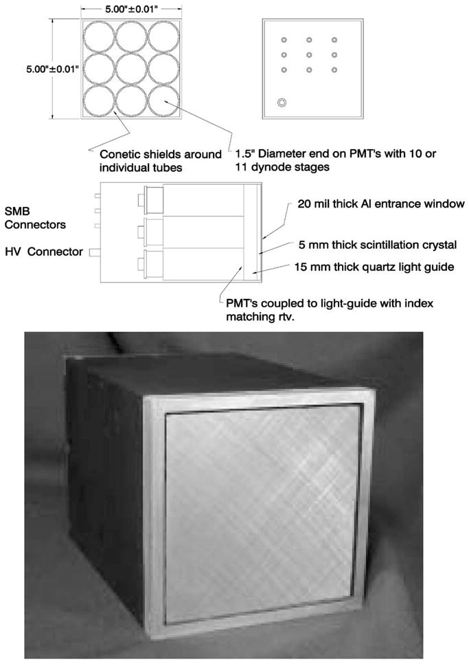
Assembly drawing and photograph of FastSPECT II 3 × 3 modular gamma-ray camera.
III. List-Mode Acquisition Electronics
The advantages of list-mode data collection, the recording of the full set of observations associated with a data event as an entry in an ordered list, have been demonstrated in prior work [12], [13]. In brief, statistical methods applied to estimate individual photon properties such as energy and position, or the photon fluence, or even the tomographically reconstructed source object always have access to the data observations at their full collected precision.
For the modular gamma-ray cameras being employed in Fast-SPECT II, each entry in the data list corresponds to a detected scintillation event and consists of a camera identifier, the nine signal values present in the 3 × 3 array of photomultipliers, and a time stamp. In our data acquisition system, the list entries are generated by a list-mode event processor implemented in programmable logic that scans streams of continuously digitized data looking for photon events, extracts the relevant set of observations and the current time, and prepares a byte packet for transmission. The data list itself is maintained in a back-end PCI card, the list-mode event buffer, that also accomplishes the computer-interfacing task.
The complete acquisition electronics package associated with a single camera is shown in Fig. 2. It should be noted that the list-mode event buffer actually supports a second camera; hence, in a system there are twice as many cameras and list-mode processors as list-mode buffers. A complete description of the electronics will be presented elsewhere [14].
Fig. 2.
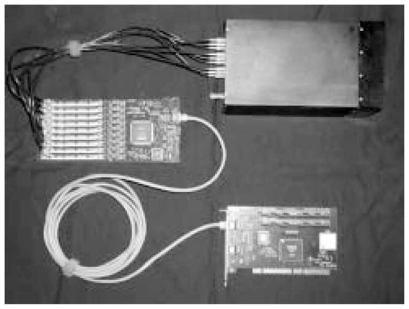
The list-mode data-acquisition components for a single FastSPECT II modular gamma-ray camera.
IV. System Gantry and Enclosure
FastSPECT II is built in and around a welded tubular aluminum framework. The cameras are arranged as two rings of eight on opposite sides of a pair of central plates. Each camera has an aluminum mounting plate that is captured in a milled recess, providing a selection of three radial positions of increasing distance (6, 9, and 12 inches) from the imager axis.
The entire imager is shielded with 1/8″ lead sheet laminated to a 1/8″ thick powder-coated aluminum skin. Access to interior components for service or to change camera locations is provided via two hinged doors as shown in Fig. 3. The entire structure is built on a heavy-duty wheeled base that permits relocation of the imager if necessary.
Fig. 3.
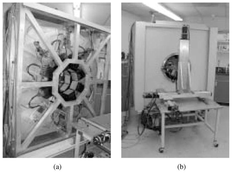
Photographs of FastSPECT II (a) prior to installation of shielding and (b) in finished condition together with calibration and positioning stage.
V. Imaging Apertures
In its initial configuration, FastSPECT II employs an array of 1 mm diameter pinholes, one per camera, as image-forming elements. The pinholes are precisely machined into gold disks that mount in appropriately milled recesses in a lead cylinder. The gold pinholes are held via retaining rings and can conveniently be exchanged if alternate aperture diameters are required. Different diameter lead cylinders are used in conjunction with the radial camera locations to select a variety of magnifications and fields of view.
In the basic geometry suitable for small-animal imaging, the pinholes are placed along imaginary lines between the center of the field of view and each camera face. This provides a magnification of approximately 3 for the smallest lead cylinder (2 inch radius) and closest camera position (6.5 inches from imager axis). The field of view then accommodates a 25–50 gram laboratory mouse, and the 16 pinholes combined provide a photon collection efficiency of ~0.04%.
VI. Calibration and Positioning system
In order to calibrate the system, it is first necessary to be able to translate a well-collimated source across the face of each camera. In this manner, a mean detector response function (MDRF) is measured that incorporates all optical and electronic properties of the camera and its acquisition chain. In a second step, a point source (usually approximated by activity adsorbed onto one or more chromatography beads) is translated throughout the object volume to build an overall imaging matrix or PSF. This in turn calibrates in all imaging properties of the system, including pinhole sizes and locations, camera orientations, and sensitivity effects.
To meet these needs, we designed and implemented a five-motion positioning system that includes four translations and a rotation. It is assembled with high-quality components from Parker–Hannifen, Irwin, PA and provides repeatable positioning with better than 0.1 mm precision. Three of the translation stages implement standard x-y-z motions. The rotation stage and the small secondary translation stage mounted on it make it possible to carry out all MDRF scans with the convenience of having two translation axes parallel to any camera face.
VII. Control and Acquisition software
FastSPECT II is controlled by two PCs running Windows® NT operating systems. A custom device driver and low-level dynamic link library are responsible for recognizing the presence of list-mode event buffer boards on the PCI bus and providing memory-mapped I/O functions. Four list-mode event buffers are located in each of the PCs to support the full complement of 16 cameras. High-level instrument control is accomplished via user interface software programmed in the LabVIEW® environment. Coordination between the two computers and control of the robotic system are all accomplished via TCP/IP communication.
A number of analysis functions were built into the acquisition package, including the ability to rapidly determine photopeak moments for the purpose of iteratively adjusting the gain in each PMT’s signal chain to match a template.
After the acquisition of list-mode calibration and imaging data, further computations and tomographic reconstructions were performed on a parallel processing cluster with roughly two dozen nodes.
VIII. Performance Measurements and Results
A. MDRF Measurements
A modular scintillation camera’s ability to provide high-resolution images is determined by the shape of its measured MDRF and by the total number of photoelectrons produced. Show in Fig. 4 below is the response of the center tube in one of FastSPECT II’s cameras as a function of gamma-ray interaction position. Fig. 5 displays a one-dimensional slice of the 2-D MDRF of a camera when the collimated source is scanned horizontally across the camera face at about the midpoint. Of particular significance for image formation are the wide dynamic range (approxmately 40:1) in signal amplitude between the maxima (corresponding to being immediately above a PMT) and minima, the monotonic attenuation with distance away from any PMT center, and the symmetric falloffs toward the camera edges.
Fig. 4.

Measured mean response of the center PMT as a well collimated source is scanned across the face of one of the FSII cameras.
Fig. 5.

Measured MDRF for the three PMTs immediately underneath a horizontal scan of a FASTSPECT II modular gamma-ray camera close to the mid-line.
MDRFs were measured for each camera in the imager on a grid of 78 by 78 points spaced 1.5 mm apart. Sealed plastic vials containing 20–40 mCi of 99mTc-pertechnitate solutions were placed in a collimator designed to produce a 1 mm diameter beam of low divergence. Approximately 5000 counts per second were recorded at the beginning of scans that each lasted just less than 4 hours.
B. PSF Measurement
A first PSF scan comprising 8000 points in a 20 mm × 20 mm × 20 mm volume (1mm3 voxels) was collected close to the center of the imager’s field of view for the purpose of capturing test images of a phantom suitable for tomographic reconstruction. The total acquisition time was approximately 5 hours, with integration times of 1 second per point. A full system PSF will eventually be collected that contains ~50, 000 grid points. The sparse nature of the data makes it possible to apply substantial compression if projected as images on each camera face. However, PSFs left in list-mode form are invariably large and even the initial scan occupied more than 4 GB of storage.
C. Phantom Imaging
A simple phantom was constructed in order to validate the imager’s operation; it consisted of six small spheres of activity attached to ends of three plastic rods arranged in orthogonal orientations. A photograph of the phantom is shown in Fig. 6 along with a familiar coin for scale. Each sphere was ~1.5 mm in diameter, and the phantom contained a total of 1 mCi of 99mTc-pertechnetate.
Fig. 6.
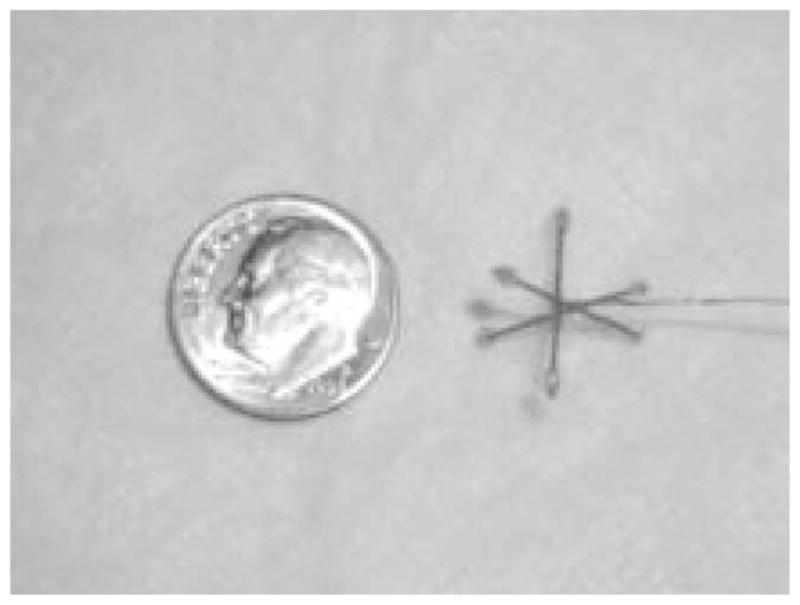
Phantom employed for first tomographic images along with a coin for scale. Total activity was ~1 mCi.
The phantom was imaged with a one-second exposure and reconstructed with 40 iterations of an ML-EM algorithm. The resulting slices are shown in Fig. 7. The spheres are fully resolved and have well defined boundaries. No individual sphere is visible in more than three vertical slices.
Fig. 7.

Tomographic slices of the phantom shown in Fig. 6. Each slice is 1 mm thick, and has lateral dimensions of 20 mm × 20 mm. Two spheres are at top edge of calibration volume.
D. Dynamic Capabilities
Data collected on FastSPECT II arrives in the controlling PCs as lists of gamma-ray events detected on each camera; each entry in the list comprises the set of nine PMT signals associated with the peak pulse amplitudes observed in that event and the time it occurred. All acquisitions are therefore dynamic in nature since the data always has time information recorded to the nearest 30 nsec interval. However, there are several additional steps required for the practical acquisition and reconstruction of true dynamic images on FastSPECT II.
For example, if images need to be synchronized to a periodic biological process such as heartbeat, a separately digitized and time-stamped physiological signal (such as EKG) will be needed in order to assign events to phases in the cardiac cycle. Real dynamic imaging techniques will also require development of new list-mode reconstruction algorithms optimized for the task.
IX. Conclusion
FastSPECT II builds on the experience gained in the operation of the original FastSPECT imager by adding a number of technical upgrades, including improved modular gamma-ray cameras, data-acquisition hardware, and calibration stages. The new modular cameras have 30% larger active areas (130 cm2 versus 103 cm2) than the original models and sense each scintillation event with nine rather than four PMTs. The digital data in the new imager is generated by 12-bit A/D converters (as opposed to eight-bit A/Ds in FastSPECT I) and stored intact without information loss by the new acquisition system.
One of the most significant improvements is the incorporation of exchangeable imaging apertures and adjustable camera locations. The imager’s sensitivity, reconstructed resolution, and field of view are not fixed, but can be selected to match imaging tasks.
The result is a flexible instrument that will be used in a variety of biomedical research applications as part of the SPECT core of a multimodality small-animal imaging resource. The dynamic capabilities of the imager will be exploited in the near future with initial demonstration applications anticipated to be in first-pass cardiac imaging and pharmacokinetics.
Acknowledgments
This work was supported by the National Institutes of Health under NIBIB Grant P41 EB002035-5 (Center for Gamma-Ray Imaging) and NCI Grant R24 CA83148 (Southwest Animal Imaging Resource).
The authors gratefully acknowledge the contributions of L. Fesler and N. Eleid in the assembly of FastSPECT II electronics and mechanical systems, respectively. J. Butters, T. Lerdal, S. Lieber, and B. Stuckey assisted with the design and preparation of construction drawings of the system gantry and stage as their senior Aerospace and Mechanical Engineering Project. D. D. Patton, MD, J. M. Woolfenden, MD, and G. Stevenson, DVM, provided valuable guidance.
Contributor Information
Lars R. Furenlid, Email: furen@radiology.arizona.edu, Department of Radiology, Division of Nuclear Medicine, University of Arizona, Tucson, AZ 85724 USA, and also with the Optical Sciences Center, University of Arizona, Tucson, AZ 85721 USA.
Donald W. Wilson, Email: dwwilson@radiology.arizona.edu, Department of Radiology, Division of Nuclear Medicine, University of Arizona, Tucson, AZ 85724 USA, and also with the Optical Sciences Center, University of Arizona, Tucson, AZ 85721 USA
Yi-chun Chen, Email: yichun@optics.arizona.edu, Optical Sciences Center, University of Arizona, Tucson, AZ 85721 USA.
Hyunki Kim, Email: hyunki@u.arizona.edu, Optical Sciences Center, University of Arizona, Tucson, AZ 85721 USA.
Philip J. Pietraski, Email: pjjp1@optonline.net, Interdigital Communication Corporation, Melville, NY 11747 USA.
Michael J. Crawford, Email: michaelc@email.arizona.edu, Optical Sciences Center, University of Arizona, Tucson, AZ 85721 USA
Harrison H. Barrett, Email: barrett@radiology.arizona.edu, Department of Radiology, Division of Nuclear Medicine, University of Arizona, Tucson, AZ 85724 USA, and also with the Optical Sciences Center, University of Arizona, Tucson, AZ 85721 USA.
References
- 1.Klein WP, Barrett HH, Pang IW, Patton DD, Rogulski MM, Sain JD, Smith WE. FASTSPECT: Electrical and mechanical design of a high-resolution dynamic SPECT imager. Proc Conf Rec 1995 IEEE NSS/MIC. 1995;2:931–933. [Google Scholar]
- 2.Kastis GK, Barber HB, Barrett HH, Gifford HC, Pang IW, Patton DD, Sain JD, Stevenson G, Wilson DW. High resolution SPECT imager for three-dimensional imaging of small animals. J Nucl Med. 1998;39(5-suppl):9–9. [Google Scholar]
- 3.Rogers JG, Saylor DP, Harrop R, Yao XG, Leitao CV, Pate BD. Design of an efficient position sensitive gamma ray detector for nuclear medicine. Phys Med Biol. 1986;31(10):1061–1090. doi: 10.1088/0031-9155/31/10/001. [DOI] [PubMed] [Google Scholar]
- 4.Milster TD, Selberg LA, Barrett HH, Easton RL, Rossi GR, Arendt J, Simpson RG. A modular scintillation camera for use in nuclear medicine. IEEE Trans Nucl Sci. 1984;NS-31:575–580. [Google Scholar]
- 5.Milster TD, Aarsvold JN, Barrett HH, Landesman AL, Mar LS, Patton DD, Roney TJ, Rowe RK, Seacat RH., III A full-field modular gamma camera. J Nucl Med. 1990;5(31):632–639. [PubMed] [Google Scholar]
- 6.Sain JD. PhD dissertation. Univ. Arizona; 2001. Optical Modeling, Design Optimization, and Performance Analysis of a Gamma Camera for Detection of Breast Cancer. [Google Scholar]
- 7.Weber DA, Ivanovic M, Franceschi D, Strand SE, Erlandsson K, Franceschi M, Atkins HL, Coderre JA, Susskind H, Button T, Ljunggren K. Pinhole SPECT: An approach to in vivo high resolution SPECT imaging in small laboratory animals. J Nucl Med. 1994;35:342–3488. [PubMed] [Google Scholar]
- 8.Ishizu K, Mukai T, Yonekura Y, Pagani M, Fujita T, Magata Y, Nishizawa S, Tamaki N, Shibasaki H, Konishi J. Ultra-high resolution SPECT system using four pinhole collimators for small animal studies. J Nucl Med. 1995;36:2282–2286. [PubMed] [Google Scholar]
- 9.De Notaristefani F, Pani R, Scopinaro F, Barone LM, Blazek K, De Vincentis G, Malatesta T, Maly P, Pellegrini R, Pergola A, Soluri S, Vittori F. First results from a YAP:Ce gamma camera for small animal studies. IEEE Trans Nucl Sci. 1996;43:3264–3271. [Google Scholar]
- 10.Schramm N, Wirrwar A, Sonnenberg F, Halling H. Compact high resolution detector for small animal SPECT. IEEE Trans Nucl Sci. 2000;47:1163–1167. [Google Scholar]
- 11.MacDonald LR, Patt BE, Iwanczyk JS, Tsui BMW, Wang Y, Frey EC, Wessell DE, Acton PD, Kung HF. Pinhole SPECT of mice using the LumaGEM gamma camera. IEEE Trans Nucl Sci. 2001;48:830–836. [Google Scholar]
- 12.Barrett HH, White T, Parra LC. List-mode likelihood. J Opt Soc Amer A. 1997;14(11):2914–2923. doi: 10.1364/josaa.14.002914. [DOI] [PMC free article] [PubMed] [Google Scholar]
- 13.Parra LC, Barrett HH. List-mode likelihood: EM algorithm and image quality estimation demonstrated on 2-D PET. IEEE Trans Med Imaging. 1998;17:228–235. doi: 10.1109/42.700734. [DOI] [PMC free article] [PubMed] [Google Scholar]
- 14.Furenlid LR, Pietraski PJ, Kim HK, Barrett HH. A list-mode data-acquisition system for gamma-ray detectors. to be published. [Google Scholar]