Abstract
Transmit and receive RF coil arrays have proven to be particularly beneficial for ultra-high-field MR. Transmit coil arrays enable such techniques as B1+ shimming to substantially improve transmit B1 homogeneity compared to conventional volume coil designs, and receive coil arrays offer enhanced parallel imaging performance and SNR. Concentric coil arrangements hold promise for developing transceiver arrays incorporating large numbers of coil elements. At magnetic field strengths of 7 tesla and higher where the Larmor frequencies of interest can exceed 300 MHz, the coil array design must also overcome the problem of the coil conductor length approaching the RF wavelength. In this study, a novel concentric arrangement of resonance elements built from capacitively-shortened half-wavelength transmission lines is presented. This approach was utilized to construct an array with whole-brain coverage using 16 transceiver elements and 16 receive-only elements, resulting in a coil with a total of 16 transmit and 32 receive channels.
Keywords: RF Coil Design, Transmit Array, Concentric Coils, 7T, Transmission Line Coils, High Field
Introduction
Ultra-high-field MR offers advantages for numerous biomedical applications such as high-resolution anatomical and functional imaging in the brain, and neurochemical spectroscopy (e.g.(1,2)). These demanding applications rely in part on inherent signal-to-noise ratio (SNR) and contrast-to-noise ratio gains provided by increasing B0 field strength. They further benefit from the additional SNR and improved parallel imaging performance that can be realized by combining high B0 fields with multi-channel receive coil arrays with large numbers of coil elements (3-7). For a given target volume, however, there are practical limits to the number and size of coils that can be utilized in an array in such a way as to yield sufficient decoupling among the different elements while at the same time retaining these SNR and parallel imaging gains. At lower magnetic fields such as 1.5 tesla, where the RF frequency of interest is in the range of 64 MHz, this limit may be relaxed considerably by employing concentric coil arrangements (8). At 7 tesla and above, where the RF frequencies approach and exceed 300 MHz, the physical coil conductor length of concentric coil arrangements will approach and even bypass the electromagnetic wavelength. Consequently, the underlying assumption for concentric coil decoupling—equal coil current distribution—is no longer true for realistic coil sizes and human imaging applications.
An alternative method for designing concentric coils is to allow in the design some B1z components that are not useful for MR signal detection. A classical surface coil, for example, does have significant—albeit often overlooked—B1z components irrespective of its orientation relative to the B0 field. Permitting the inclusion of such components in the design obviously increases the number of potential configurations. Presence of the B1z components in the transmitting elements is generally not desirable due to increased power requirements and power deposition. On the receive side however, inclusion of coil elements with stronger B1z components is expected to be still beneficial for improved SNR and parallel imaging performance as long as all receive coils are designed to ensure low level of noise correlation. This can be achieved for example by orthogonality of the elements. Additionally the array has to contain coil elements that cover the void in the imaging volume where the array elements with stronger B1z components have minimal or no sensitivity. In such a case the parallel imaging performance of the entire array will still improve due to uniqueness of the resulting sensitivity profiles. Thus, concentrically configured coils are potentially appealing and worth evaluating as possible alternative arrangements suitable for high frequency even if in so doing elements are introduced which have some B1z components.
It is clear that, foremost, such coils need to have significantly shorter conductor structures at high frequencies compared to the proposed arrangements at ∼64 MHz (8). For example, at 300 MHz, for transmission line coils built with a Teflon dielectric of εr∼2.1, this dimension can typically be on the order of ∼70 cm. Assuming a realistic average tissue εr∼50 for the human head, the wavelength within the biological sample to be imaged is further reduced, contributing to significant RF inhomogeneity even for head-sized coil geometries. One elegant way to achieve very short conductor length is to utilize capacitively-shortened straight transmission line elements. It has been demonstrated that such elements can support high transmit efficiency, excellent parallel imaging performance, and good B1 penetration, particularly at high frequencies (9-11).
In this work, we consider an alternative coil arrangement that utilizes transmission lines as the primary building block in two concentric rings for both the transmit and the receive coil arrays. Since transmit arrays with a large number of independent transmit channels are of considerable interest for RF transmission at ultra-high fields (12), we designed the outer ring as a 16-channel transceiver array that allows for independent transmit phase and amplitude control. This 16-element transceiver array was then combined with a second 16-channel receive-only array of short transmission lines. This combination resulted in an array with 16 transmit and 32 receive channels. Thus, a unique feature of the array is the concept that while one set of elements act as a transmit array, the same set of elements also acts as a receive array in combination with a separate receive-only array. In the particular design employed, the outer ring is a transmit array capable of B1 shimming and Transmit-SENSE operations, and the inner ring is a receive-only array. However, both the outer and the inner rings are used as the receive array. The specific design utilized in this study also demonstrates that transmission line elements can be used both in parallel and perpendicular orientation to the main static magnetic field. We present results evaluating whether the proposed transceiver + receive-only combination array improves SNR and parallel imaging performance (i.e. SENSE (13)) compared to a 16-channel transceiver transmission line array. It should be noted, however, that the transmission line arrangement proposed in this study, while beneficial in many aspects, does not represent an optimal receive array configuration. Here, for example, Wiggins, et al. have clearly demonstrated the benefits of receive arrays at 3 T and 7 T built with a high number of small loop coils mounted on a close fitting former (14).
Methods
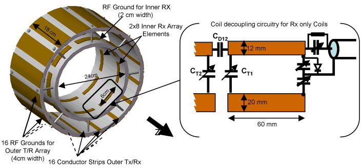
The 16-channel outer transmit array (11) with an inner diameter of 32 cm was built with decoupling capacitors between elements (15-17) to achieve element decoupling and thus allowing for independent element control. The individual elements were adjusted for λ/2 resonance; high-voltage ceramic chip capacitors (6.8pF, ATC 100E) were used to capacitively shorten the individual resonance elements. Variable capacitors (Voltronic NMNT6-10) on the feed end of the line allowed for tune and match adjustments. These capacitors shorten the effective electrical resonator length and significantly reduce the B1 field variation over the conductor (18). The individual resonance elements were built from strips of 12 mm-wide adhesive-backed copper tape (3M, St. Paul, USA) equally spaced on cylindrical 12 mm-thick Teflon formers (Fig. 1A). The ground conductor for each transmit array element was 4 cm wide and electrically separated from neighboring elements. A second coil array was built using a 1 cm-thick Teflon cylinder of 24 cm inner diameter. Two sets of eight stripline elements, each 6 cm long, were arranged perpendicular to the main static field direction, as depicted in Fig. 1B and 2. To decrease the RF shielding effect during transmission, the width of the ground plane for these coils was reduced to 20 mm. The spacing along the z direction between the two sets of eight coils was 10 cm. A PIN diode shortened each 6 cm-long resonance element of the inner coil towards ground during signal transmission (see Fig. 2).
Figure 1.
The 32-channel Lattice array. A: The outer 16-channel transceiver array, 32 cm i.d. B: The 16-channel concentric receive-only array, 24 cm i.d. C: The combined 16-channel tranmit/32-channel receive lattice coil.
Figure 2.
Sketch of the circuitry for the inner receive array, depicting balanced output circuitry and capacitive decoupling between adjacent elements. Also shown is the PIN diode that aided isolation from the outer transmit array during RF transmission.
Imaging experiments were performed on a 7 T magnet (Magnex Scientific, Oxford, UK) equipped with a Siemens console with 32 receive channels based on TIM and Avanto body gradient technologies. An 8 kW RF amplifier (CPC, Brentwood, NY) was utilized and the RF transmit power was divided with a 16-channel equal amplitude splitter (Werlatone, Brewster, NY). The sixteen individual splitter paths had a pre-adjusted phase difference of 22.5° between neighboring ports, thus covering a phase range from 0° to 337.5°. All data presented here were acquired with equal RF transmit power applied to each channel. Commercially available transmit/receive (T/R) switches (Stark Contrast, Erlangen, Germany) in each of the 16 transmit paths blocked transmitter noise during reception and enabled the use of low noise preamplifiers in close proximity to the coil. The T/R switch circuitry was designed to utilize 16 of the regular system PIN control voltages and currents (-30 V/+100 mA).
Bench measurements were performed using a calibrated HP 4396A (Hewlett Packard, Palo Alto, CA, USA) network analyzer together with an 85046A “S”-parameter test set. We imaged healthy volunteers who had signed a written consent form approved by the Institutional Review Board of the University of Minnesota.
B1+ maps were obtained with excitation through all 16 transmit channels together utilizing the actual flip angle (AFI) imaging technique described by Yarnykh (19). In order to calculate the sum of the magnitude of the transmit B1+ field of each individual transmit element, a series of FLASH images were obtained transmitting through one channel at a time while receiving through all receive channels simultaneously, as described by Van de Moortele (20).
In order to generate SNR maps, FLASH images were obtained with the following parameters: TR/TE: 8000/3.5 ms; voxel size = 1 × 4 × 4 mm, bandwidth = 300 Hz/pixel; nominal flip angle = 80°. The images were normalized to the noise measured in a separate acquisition without RF acquisition as well as to the sine of the actual excitation flip angle derived from the B1+ map. The SNR was calculated separately for the outer transmit array and for the inner receive array. For comparison, the sum of those two SNR maps was also calculated, divided by √2 to account for the noise averaging.
Parallel imaging performance was evaluated in terms of the g-factor as described in (13). 2D images covering the whole brain were acquired in axial, coronal, and sagittal planes using a standard FLASH sequence (TR/TE: 100/8 ms; flip angle = 10° at the center of the head; resolution = 0.5 × 0.5 × 5 mm). The field of view (FOV) was 25.6 × 25.6 cm. The larger FOV was subsequently cropped to be tight to the head in both the readout and phase encoding directions. The g-factors were calculated from the tight FOV sensitivity profile images, which were calculated as the ratio of images from individual channels to the root-sum-of-squares image of all channels (13). The tight FOV ensured that the maximum aliasing present was equal to the reduction factors used. This is not the case when an excessively large FOV is used, since the resulting g-factor underestimates the g-factor relative to a tight FOV. For the estimation of the average g-factors, 2D reduction factors up to 4 × 4 were evaluated. Additional acquisitions were obtained without RF pulsing in order to record noise data for all channels for the purpose of evaluating the noise correlation between channels.
Results and Discussion
Decoupling capacitors (with values ∼2.5 pF and ∼1 pF, respectively, for the outer and inner coils) were necessary between neighboring elements in the two concentric arrays. The perpendicular transmission line coil arrangement aided by the physical distance between the inner and outer array of around 3 cm was found to provide sufficient coil isolation (>-20 dB), such that additional decoupling circuitry between the inner and outer arrays was not needed. The individual transmission line resonance elements could be tuned and matched independently and no resonance peak split was observed. While preamplifier decoupling (21) certainly has the potential to further reduce the noise correlation between the coils, it was found that such additional decoupling means were not required in the presented perpendicular coil arrangement. We considered RF shield widths of 30 mm, 20 mm, and 12 mm for the inner receive-only coils, and chose 20 mm after preliminary bench measurements. For this we measured relative transmit efficiency of a transmit element to a pick-up coil positioned 15 mm from the inner receive elements of the mentioned shield widths. Additionally we evaluated coupling between the coils and the sensitivity of the receive coils. Shield widths of 30 mm, 20 mm, and 12 mm reduced transmit efficiency in the described location by 0.9 dB, 0.25 dB, and 0.1 dB, respectively, compared to the “ideal” situation without any shield. However, coil decoupling was reduced for the coils with the wider shield, and a width of 20 mm was chosen as a compromise between the desire to reduce inter-element coupling through RF shielding while maintaining minimal transmission line characteristics and achieving sufficient transparency during RF transmission. The remaining most difficult to adjust coil coupling was found to be related to the routing of the coaxial receive cables of the inner array, since these cables run in close proximity (∼2 cm) parallel to the outer array transmit elements. By reducing the number of physical locations where the coaxial receive cables run along the transmit elements to four (0°, 90°, 180°, 270°), capacitively separating the coaxial receive line ground and the RF shield ground, and by using balanced output circuitry for all inner receive transmission line strips, however, we were able to address this issue and reduce the worst-case coil coupling to values typically better than -15 dB.
The introduction of the PIN diode into the circuitry of the inner transmission line receive array furthermore improved the decoupling between the outer transceiver array and the inner receive-only array by -20 dB. This resulted in typical coil decoupling values between the arrays during the RF signal transmission of at least ∼-35 dB. The effectiveness of the decoupling between the inner and outer coil during signal transmission was also evaluated by comparing the RF power requirements with the same subject and head position in the coil for the transmit array only (the inner receive array was physically removed for this experiment) vs. the complete 32-channel lattice array. We observed a maximum increase in transmit power requirement on the order of 1 dB.
Unloaded (QU) and loaded (QL) Q measurements were obtained to evaluate coil efficiency and sample load dependence of the individual array coil elements. While the unloaded Q values for all transmission line elements were similar and measured to be around 280 +/- 40, the loaded Q varied more widely depending on head size and relative position of the elements to the load. As expected, the QU/QL ratios of the receive-only coil elements were generally higher than those of the outer T/R coil elements due to the closer proximity to the load. The QU/QL ratios for the receive-only coil elements ranged from 5 to 6 for posterior elements (medium to large head) to 2 to 4 for lateral elements. As expected, the QU/QL ratios of anterior elements were heavily dependent on the head size and consequently spanned a wider QU/QL range from 3 to 6. Compared to closer fitting, receive only elements, the average Q ratios of the sixteen outer T/R coil elements are generally lower and ranged from 3 to 4 for posterior elements to 1.5 to 2 for lateral elements. Again anterior elements experienced the widest changes in QU/QL ratios ranging from 1.5 to 3, depending on the size and relative position of the head load. The observed potential for significant reduction in QU/QL ratios of anterior and lateral elements compared to posterior elements, point to the potential benefits of closer fitting elliptical coils versus circular coil designs at 7 tesla [14].
We than compared the overall transmit power requirements for the presented coil to that of a close-fitting elliptical 16-channel transmission line array (22) and to a 27 cm i.d. TEM coil and found that the 32 cm transmit array typically required an additional 4-6 dB compared to these more optimal transmit coils. In order to distinguish between the reduction in transmit efficiency due to the larger coil diameter versus the influence of the decoupling methodology we compared a 16 element TEM coil (27 cm i.d.) with a 16 channel transmission line array of similar geometry. Here the TEM coil typically required 1 to 2 dB less transmit power. The main reason for the increase in transmit power requirements for the 32 cm transmit array is thus the larger distance between the conductors of the transmit array and the sample.
To ensure maximal transmit efficiency and to protect the T/R switch from high reflected power, performing tune and match capacitor adjustment on the outer 16 transmit array elements for individual subjects was found to be beneficial. However, it was not necessary to adjust the decoupling capacitors of the outer transmit and receive coil elements on a subject-by-subject basis. Similarly, the tune/match and decoupling capacitor values of the inner array were adjusted only once in a bench measurement for the human head but otherwise not changed from these pre-adjusted values between subjects. This is an important practical consideration since readjustment of the inner receive elements for each subject would be too time-consuming to realistically allow for routine clinical use of the coil.
The 16 transmit elements were driven individually with 16 separate RF inputs, which permitted phase and amplitude adjustments on each channel separately, as previously shown (9,22,23). However, for the scope of this work, we found that phase adjustments for the individual transmit channels were not required and the transmit phases for all experiments presented in this paper were set to 22.5° phase increments between adjacent channels. We were also able to limit all our experiments reported in this paper to an equal power distribution between the transmit resonance elements. We attributed this to the relatively large diameter of the transmit array compared to the sample size (24).
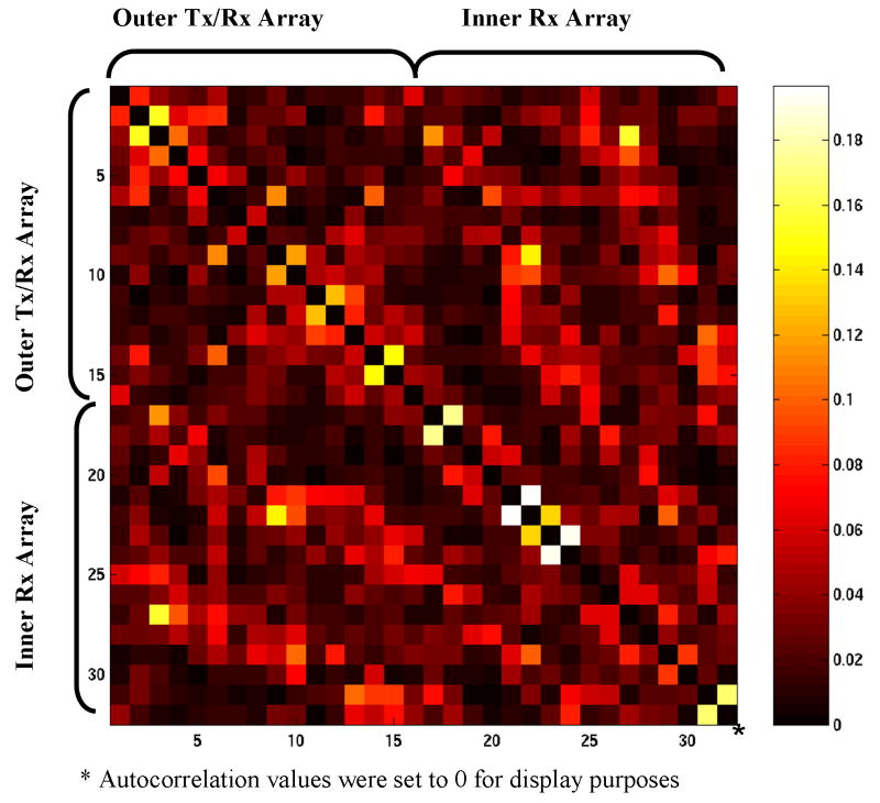
The noise correlation matrix of the combined 32-element coil (Fig. 3) indicated generally excellent isolation and minimal crosstalk between the two arrays and the individual elements. This is particularly encouraging since the data were acquired during signal reception when all coils are active and the PIN diodes are back biased, thus not aiding the decoupling. The values of highest correlation (between coils #17-#18, #21-#22, and #23-#24, respectively) were typically found to be between neighboring coils in the inner receive array. We attributed this to the lack of individual decoupling capacitor readjustments between subjects. Nevertheless, the noise correlation values for various subjects were always within the acceptable range: i.e., below 20%.
Figure 3.
Noise correlation matrix. Each axis depicts coil element numbers: 1 to 16 are the outer transceiver array elements oriented parallel to the z-axis. Channels 17 to 32 are the inner radial elements.
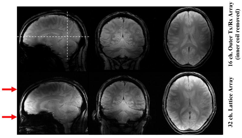
Figure 4 illustrates the effects that the inner ring coils have on the performance of the array. The red arrows next to the sagittal images indicate the approximate position of two axial planes containing the stripline elements that are located on the inner ring and that are oriented perpendicular to the main static field (z-axis). The dashed lines running through the top sagittal image identify the approximate location of the adjacent coronal and axial slice images in this figure. A clear gain in SNR, particularly in the area between the two axial planes containing the coil elements of the inner ring (i.e., between the two red arrows on the sagittal plane) is seen when utilizing the 32-channel lattice array (Fig. 4, lower row) vs. only the 16-channel transceiver array with linear elements running along the z direction (i.e. the outer ring) (Fig. 4, upper row). Because of this gain, the central axial slice shown (Fig. 4, lower row) displays higher signal intensity everywhere and the coronal slice shows a higher intensity centrally when acquired with 32 elements (Fig. 4 lower row) vs. just the outer ring 16 elements (Fig. 4 upper row). As expected, the gain is less pronounced for regions in the vicinity of the two axial planes containing the inner coil elements. This is easily appreciated in the sagittal slice again where the presence of the inner ring does not affect the intensity at the level of the red arrows. This is expected because the prominent B1z components of the inner ring elements tend to dominate on the axial plane containing these elements (Fig. 4). In principle, the SNR gains attained with the inner ring of coils can be extended further in space to cover the entire brain by using additional elements on the inner ring placed circumferentially on additional axial planes, resulting in an array with more than 32 elements. However, this was not feasible with the total number of receivers available on our system.
Figure 4.
Shows the relative SNR comparison between the 16-channel, outer transmit/receive array only (upper row) and the 32-channel lattice array (lower row). For the acquisition of the transmit-array-only data set (upper row), the inner array was physically removed. The red arrows indicate the approximate position of the axial planes containing the circumferentially located, inner ring coil elements that run perpendicular to the z- axis (see Fig. 1).
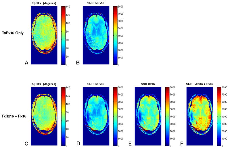
Figure 5 complements Figure 4 for a central axial plane and quantitatively sums up a number of important points. The flip angle achievable in any pixel (i.e., the sum of the B1+ magnitude of each outer transmit coil element) was compared in the case of using only the outer coil (Fig. 5A: for this, the receive-only array was physically removed and the subject carefully repositioned) to the case with the inner receive coil in place (Fig. 5C). There is no noticeable difference between these two cases indicating the good RF transparency of the inner receive array coils. Figures 5B and 5D indicate the achievable SNR using the outer transceiver coil with and without the inner coils, respectively. Likewise, the lack of noticeable difference demonstrates the good coil decoupling. Figure 5C shows the SNR map for the inner receive coil only and Figure 5D shows the gains in SNR typically achieved when combining the contributions of all coils.
Figure 5.
A,B. Parametric maps obtained with the outer transmit array only (A,B) and the lattice coil combination of transmit and receive array (C-F). A,C: Shows the sum of the magnitude B1+ of each transmit element (expressed as flip angle in degrees). B,D-F: Shows SNR maps of the individual arrays (B,D,E) and the combination of all coils (F). For the acquisition of the transmit-array-only data set (upper row, A,B) the inner array was physically removed.
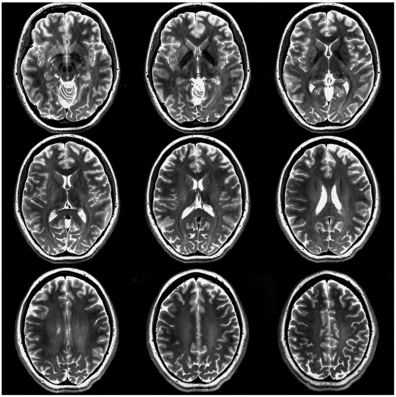
Figure 6 illustrates representative intensity-corrected T2-weighted multi-slice hyperecho turbo-spin-echo images obtained with the 32-element array.
Figure 6.
T2 Weighted hyperecho turbo-spin-echo images with the 32-channel lattice array: 16-channel outer transceiver + 16-channel inner receive-only. Matrix (acquired) = 512 × 512; resolution (acquired) = 0.375 × 0.375 × 2.0 mm; averages = 1; acquisition time = 4:41; TR = 5 sec; TE (effective) = 78 ms; turbo factor = 9.
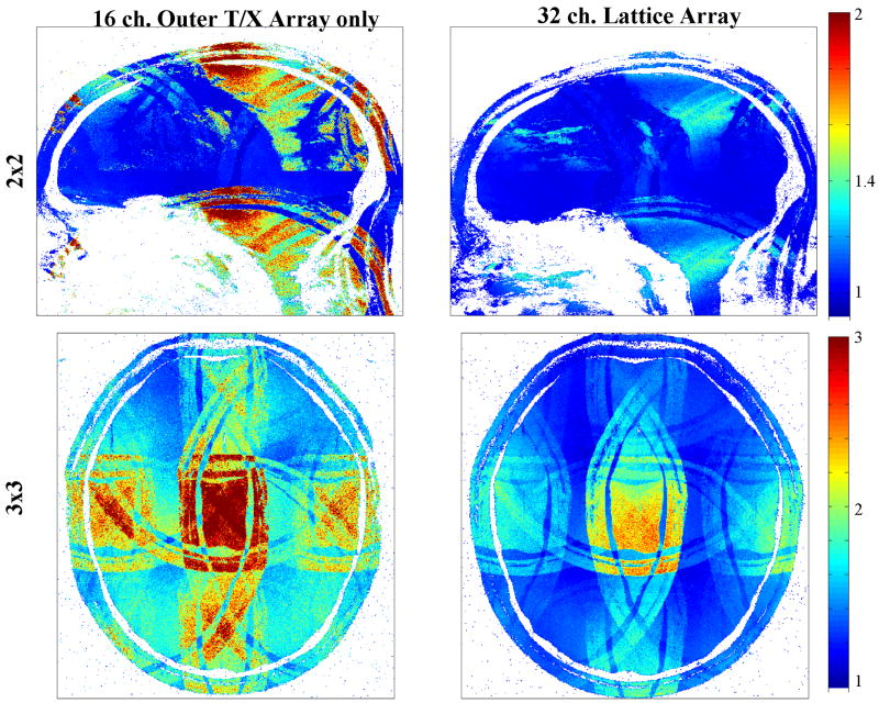
Clear parallel imaging related improvements were established as indicated by Figure 7 and related Table 1 and Table 2. As expected, the most significant improvements were observed in sagittal and coronal imaging planes. For a 3 × 3 reduction factor, for example, the achievable average g-factor in a central sagittal slice improved from 2.49 to 1.50. The improvement for axial planes is less pronounced and varies more depending on the slice position (not shown). Still, for the central axial slices located between the two concentric eight element rings, we consistently observed noticeable gains, as indicated in Figure 7 and Table 2.
Figure 7.
Average g-factor maps for the 16-channel transceiver coil alone and the 32-channel lattice coil. Shown maps are with 2 × 2 reduction for a sagittal plane and 3 × 3 reduction for a central axial plane.
Table 1.
Tabulated is the average g-factor for 2D reduction factors of axial, coronal, and sagittal slices obtained with the outer transceiver array only. For each plane the encoding axis corresponding to the horizontal row is identified above the table, with the vertical row corresponding to the other orthogonal dimension for that plane. Reduction factors also correspond to maximal aliasing.
| Axial Encoding Direction (x) |
Coronal Encoding Direction (y) |
Sagittal Encoding Direction (z) |
||||||||||
|---|---|---|---|---|---|---|---|---|---|---|---|---|
| R=1 | R=2 | R=3 | R=4 | R=1 | R=2 | R=3 | R=4 | R=1 | R=2 | R=3 | R=4 | |
| R=1 | 1.00 | 1.03 | 1.04 | 1.43 | 1.00 | 1.03 | 1.13 | 1.34 | 1.00 | 1.02 | 1.12 | 1.41 |
| R=2 | 1.03 | 1.08 | 1.24 | 1.61 | 1.17 | 1.25 | 1.48 | 1.85 | 1.16 | 1.25 | 1.46 | 1.89 |
| R=3 | 1.17 | 1.25 | 1.66 | 2.45 | 1.67 | 1.84 | 2.37 | 3.07 | 1.60 | 1.90 | 2.49 | 3.31 |
| R=4 | 1.52 | 1.66 | 2.29 | 3.96 | 2.45 | 2.75 | 3.56 | 4.71 | 2.26 | 2.88 | 4.02 | 5.71 |
Table 2.
The format, including slices, is the same as for Table 1, but the images were acquired using the combined lattice coil (16-channel outer transceiver array and 16-channel inner receive-only array). The subject was carefully positioned in the same spatial location with respect to the outer transmit array as in Table 1.
| Axial Encoding Direction (x) |
Coronal Encoding Direction (y) |
Sagittal Encoding Direction (z) |
||||||||||
|---|---|---|---|---|---|---|---|---|---|---|---|---|
| R=1 | R=2 | R=3 | R=4 | R=1 | R=2 | R=3 | R=4 | R=1 | R=2 | R=3 | R=4 | |
| R=1 | 1.00 | 1.02 | 1.12 | 1.39 | 1.00 | 1.03 | 1.14 | 1.35 | 1.00 | 1.04 | 1.13 | 1.38 |
| R=2 | 1.03 | 1.06 | 1.18 | 1.51 | 1.06 | 1.12 | 1.24 | 1.50 | 1.06 | 1.13 | 1.26 | 1.55 |
| R=3 | 1.13 | 1.17 | 1.39 | 1.89 | 1.26 | 1.33 | 1.49 | 1.80 | 1.20 | 1.31 | 1.50 | 1.89 |
| R=4 | 1.43 | 1.51 | 1.89 | 2.53 | 1.53 | 1.63 | 1.85 | 2.24 | 1.45 | 1.60 | 1.90 | 2.44 |
Conclusion
These results demonstrate that concentric arrangements of transmission line arrays are feasible at 7 T. Such arrangements significantly improve the achievable reduction factors particularly in coronal and sagittal planes, and similar improvements can be expected for oblique slices. Another noteworthy result is that the achievable coil decoupling is sufficient to allow simultaneous reception with both a transceiver array and a receive-only array without requiring active decoupling means such as preamplifier decoupling or PIN diodes. It can be expected that the concept of using transceiver array elements together with dedicated receive-only arrays can be further extended to other coil designs than transmission lines when using preamplifier decoupling for all receive elements. Future work will have to focus on improving the attainable transmit efficiency by reducing the diameter of the transmit array, and on increasing the efficiency and number of receive elements further, e.g. by combining strip elements with loop elements.
Acknowledgments
This work was supported by NIH grants P41 RR08079, P30-NS057091, EB000331 the W.M. Keck Foundation, and the MIND Institute. The 7 tesla system acquisition was funded by the W. M. Keck Foundation, NSF grant 9907842, and NIH grant S10 RR1395.
References
- 1.Ugurbil K, Hu X, Chen W, Zhu XH, Kim SG, Georgopoulos A. Functional mapping in the human brain using high magnetic fields. Philos Trans R Soc Lond B Biol Sci. 1999;354(1387):1195–1213. doi: 10.1098/rstb.1999.0474. [DOI] [PMC free article] [PubMed] [Google Scholar]
- 2.Gruetter R, Ugurbil K, Seaquist ER. Steady-state cerebral glucose concentrations and transport in the human brain. J Neurochem. 1998;70(1):397–408. doi: 10.1046/j.1471-4159.1998.70010397.x. [DOI] [PubMed] [Google Scholar]
- 3.Keltner JR, Carlson JW, Roos MS, Wong ST, Wong TL, Budinger TF. Electromagnetic fields of surface coil in vivo NMR at high frequencies. Magn Reson Med. 1991;22(2):467–480. doi: 10.1002/mrm.1910220254. [DOI] [PubMed] [Google Scholar]
- 4.Chen CN, Sank VJ, Cohen SM, Hoult DI. The field dependence of NMR imaging. I. Laboratory assessment of signal- to-noise ratio and power deposition. Magn Reson Med. 1986;3(5):722–729. doi: 10.1002/mrm.1910030508. [DOI] [PubMed] [Google Scholar]
- 5.Vaughan JT, Garwood M, Collins CM, Liu W, DelaBarre L, Adriany G, Andersen P, Merkle H, Goebel R, Smith MB, Ugurbil K. 7T vs. 4T: RF power, homogeneity, and signal-to-noise comparison in head images. Magn Reson Med. 2001;46(1):24–30. doi: 10.1002/mrm.1156. [DOI] [PubMed] [Google Scholar]
- 6.Wiesinger F, Van De Moortele PF, Adriany G, De Zanche N, Ugurbil K, Pruessmann KP. Parallel imaging performance as a function of field strength - An experimental investigation using electrodynamic scaling. Magnetic Resonance in Medicine. 2004;52(5):953–964. doi: 10.1002/mrm.20281. [DOI] [PubMed] [Google Scholar]
- 7.Wiggins CG, Potthast A, Triantafyllou C, Lin FH, Benner T, Wiggins CJ, Wald LL. A 96-channel MRI system with 23- and 90-channel phase array head coils at 1.5 tesla. Proceedings 13 th ISMRM; Miami Beach, Florida, USA. 2005; p. 671. [Google Scholar]
- 8.Ohliger MA, Greenman RL, Giaquinto R, McKenzie CA, Wiggins G, Sodickson DK. Concentric coil arrays for parallel MRI. Magn Reson Med. 2005;54(5):1248–1260. doi: 10.1002/mrm.20647. [DOI] [PubMed] [Google Scholar]
- 9.Adriany G, Van de Moortele PF, Wiesinger F, Moeller S, Strupp JP, Andersen P, Snyder C, Zhang X, Chen W, Pruessmann KP, Boesiger P, Vaughan T, Ugurbil K. Transmit and receive transmission line arrays for 7 tesla parallel imaging. Magn Reson Med. 2005;53(2):434–445. doi: 10.1002/mrm.20321. [DOI] [PubMed] [Google Scholar]
- 10.Kumar A, Bottomley PA. Optimizing the intrinsic signal-to-noise ratio of MRI strip detectors. Magnetic Resonance in Medicine. 2006;56(1):157–166. doi: 10.1002/mrm.20915. [DOI] [PMC free article] [PubMed] [Google Scholar]
- 11.Snyder C, DelaBarre L, Akgun C, Moeller S, Adriany G, Ugurbil K, Vaughan JT. High-Field Transmission Line Arrays for Transmit and Receive. Seattle, USA: 2006. p. 421. [Google Scholar]
- 12.Moeller S, Van de Moortele PF, Goerke U, Adriany G, Ugurbil K. Application of parallel imaging to fMRI at 7 Tesla utilizing a high 1D reduction factor. Magn Reson Med. 2006;56(1):118–129. doi: 10.1002/mrm.20934. [DOI] [PubMed] [Google Scholar]
- 13.Pruessmann KP, Weiger M, Scheidegger MB, Boesiger P. SENSE: sensitivity encoding for fast MRI. Magn Reson Med. 1999;42(5):952–962. [PubMed] [Google Scholar]
- 14.Wiggins GC, Triantafyllou C, Potthast A, Reykowski A, Nittka M, Wald LL. 32-channel 3 Tesla receive-only phased-array head coil with soccer-ball element geometry. Magn Reson Med. 2006;56(1):216–223. doi: 10.1002/mrm.20925. [DOI] [PubMed] [Google Scholar]
- 15.Wang J. A novel method to reduce the signal coupling of surface coils for MRI. Proc International Society for Magnetic Resonance in Medicine. 1996;3:1434. [Google Scholar]
- 16.Jevtic J. Ladder network for capacitive decoupling in phased-array coils. Proc International Society for Magnetic Resonance in Medicine. 2001;1:17. [Google Scholar]
- 17.Kumar A, Bottomley PA. Tunable planar strip array antenna. Honolulu, Hawaii, USA: 2002. p. 322. [Google Scholar]
- 18.Zhang X, Ugurbil K, Chen W. Microstrip RF surface coil design for extremely high-field MRI and spectroscopy. Magn Reson Med. 2001;46(3):443–450. doi: 10.1002/mrm.1212. [DOI] [PubMed] [Google Scholar]
- 19.Yarnykh VL. Actual flip-angle imaging in the pulsed steady state: a method for rapid three-dimensional mapping of the transmitted radiofrequency field. Magn Reson Med. 2007;57(1):192–200. doi: 10.1002/mrm.21120. [DOI] [PubMed] [Google Scholar]
- 20.Van de Moortele PF, Snyder CJ, DelaBarre L, Adriany G, Vaughan JT, Ugurbil K. Calibration tools for RF shim at Very High Field with multiple element RF coils: from ultra fast local relative B1+/- Phase to absolute magnitude B1+ mapping. Proceedings of the 15th ISMRM; Berlin, Germany. 2007; 1676. [Google Scholar]
- 21.Roemer PB, Edelstein WA, Hayes CE, Souza SP, Mueller OM. The NMR phased array. Magn Reson Med. 1990;16(2):192–225. doi: 10.1002/mrm.1910160203. [DOI] [PubMed] [Google Scholar]
- 22.Adriany G, Van de Moortele PF, Ritter J, Moeller S, Auerbach EJ, Akgun C, Snyder CJ, Vaughan T, Ugurbil K. A geometrically adjustable 16-channel transmit/receive transmission line array for improved RF efficiency and parallel imaging performance at 7 Tesla. Magn Reson Med. 2008;59(3):590–597. doi: 10.1002/mrm.21488. [DOI] [PubMed] [Google Scholar]
- 23.Metzger GJ, Snyder CJ, Akgun C, Vaughan JT, Ugurbil K, Van de Moortele P. Local B1+ shimming for prostate imaging with transceiver arrays at 7 tesla based on subject dependent transmit phase measurements. Magn Reson Med. 2008;59(2):396–409. doi: 10.1002/mrm.21476. [DOI] [PMC free article] [PubMed] [Google Scholar]
- 24.Van de Moortele PF, Akgun C, DelaBarre L, Snyder CJ, Vaughan JT, Ugurbil K. Impact of coil diameter and number of coil elements on B1 destructive interferences with Stripline coil arrays at 7 tesla. Proc 14th ISMRM; Seattle, USA. 2006; p. 3535. [Google Scholar]


