Abstract
We describe strategies to curve, rotate, align and bond precisely patterned two dimensional (2D) nanoscale panels using forces derived from a minimization of surface area of liquefying or coalescing metallic grains. We demonstrate the utility of this approach by discussing variations in template size, patterns and material composition. The strategy provides a solution path to overcome the limitation of inherently two dimensional lithographic processes by transforming 2D templates into mechanically robust and precisely patterned nanoscale curved structures and polyhedra with considerable versatility in material composition.
Introduction
Atoms at the surface of a solid are chemically bonded to fewer neighbors than in the bulk. This reduced bonding of surface atoms results in an energy penalty or surface energy associated with the creation of a surface.1–2 Surface forces then act to reconstruct or reshape surfaces to minimize this energy penalty and thereby move the system to equilibrium. The effects of the resulting stress associated with a minimization of surface energy are more readily observed in easily deformable liquids as compared to solids. Water droplets, for example, have spherical contours, since for a given volume, the sphere has the smallest surface area. On the macroscale, the spontaneous formation of liquid shapes with a spherical geometry has been widely utilized to fabricate curved optical lenses and minimal energy surfaces.3
Since the pioneering development of the controlled collapse flip-chip bonding process in the late 1960s,4 the high surface energies of molten metals and alloys have been widely utilized to align 5 and rotate 6 meso- and microscale structures. Due to the strong cohesion in metals, the surface energy of molten metals is very high (e.g. tin (Sn), 600 mN/m at 300 °C,7) when compared to that of liquids with weaker intermolecular bonds such as water (71.98 mN/m at 25 °C, 8) and molten polymers (e.g. polyethylene, 23.3 mN/m at 193 °C, 9). Hence, surface forces that result from a minimization of the surface area of molten alloys have been widely utilized to direct assembly, such as in the fabrication of free-standing micropolyhedra around solder droplets,10 and hinges.11
Apart from assembly with molten alloys, the advent of self-assembled monolayer methods in the 1980s enabled the selective manipulation and patterning of surface energies with a wide variety of materials. Consequently, surface forces were widely utilized in meso- and microscale self-assembly with a wide range of materials, including organic liquids and even water. 12–16 As a result, it has been well established that surface forces exerted by liquid drops can be utilized to curve, rotate, align and bond structures on the millimeter and microscale.
Since surface forces scale linearly with length, they become orders of magnitude larger than, for example, gravitational forces (which scale as the length cubed) at small size scales. As a result, the large magnitudes of the surface energies typically associated with molten alloys are not really required to enable assembly at small size scales. Rather, the surface forces associated with minimization of area of liquids composed of most materials are significant in terms of their relative strength. This feature is especially true at the nanoscale where a significant fraction of atoms are at the surface as compared to the bulk. Hence, surface forces dominate and their relative magnitude becomes very large. The importance of surface forces at small size scales can be readily observed in the spontaneous assembly of vesicles and liposomes. At the nanoscale, assemblies involving nanoparticle aggregation17–18 and nanowire bonding using adhesives19 and solder20 have also been demonstrated.
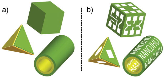
Here, we describe how surface forces can be used to address a critical challenge in nanotechnology: three dimensional (3D) nanofabrication with precise patterning. Though precise sub-100 nm resolution patterning can be achieved using advanced-optical 21 or imprint 22 lithography and maskless direct-write techniques, 23–24 it is still extremely challenging to create 3D patterned nanostructures at these small nanoscale dimensions (Fig. 1). This limitation is due to the inherent planar and serial traits of many nanoscale lithographic approaches. As a result, structures that are simultaneously curved and require patterning along orthogonal planes are prohibitively expensive, or in some cases impossible, to fabricate. Hence, there is a pressing need to engineer unconventional nanofabrication methods 25 such as molding, printing, stamping and self-assembly.
Figure 1. Schematic depicting the nanofabrication limitation being addressed.
(a) Nanofabrication has progressed sufficiently so that it is possible to create curved and polyhedral nanostructures with a variety of geometries, but with limited or no surface patterning. (b) We show that surface forces can be used to curve, rotate, align and bond panels so that any desired patterns can be incorporated onto the surfaces of curved and polyhedral nanostructures.
The availability of patterned nanostructures is critical to building complex devices since patterning codes information and enables heterogeneous integration. Lithographic patterning in quasi-3D geometries has enabled very large scale integration of heterogeneous materials, such as semiconductors, insulators and metals, to form functional logic and memory circuits.26 Patterns of metals and dielectrics are needed to create novel optical, metamaterial, plasmonic and biosensing devices. 27 In targeted therapeutics, patterns on the surfaces of nanoparticles can be used to code information for precise docking and enable multifunctionality. It is well known that nanoscale pathogens such as viruses have surface patterns. 28–29 Surface patterning is also essential to enable the bottom-up self-assembly of periodic structures. In the absence of any patterns, only simplistic close-packed structures can be formed. At the present time, most of the building blocks in nanotechnology such as nanowires, nanotubes and other nanoparticles have only very limited surface patterns. In bottom-up aggregation, it is clear that components with complex surface patterns can result in more complex assemblies. For example, as compared to self-assembly of components with relatively simple surface patterns, 30 it was shown that if components could be patterned with solder connectors and wired electronic devices on their surfaces, one could self-assemble complex 3D electrical networks with both serial and parallel connectivity. 31 The previous demonstration, however, was done with millimeter scaled components fabricated manually by hand, and the fabrication of such complex, 3D-patterned nanoscale components has yet to be achieved. Hence, in order to enhance the functionality of individual nanoscale components, as well as their aggregates, there is an urgent need to develop methods to fabricate 3D-patterned nanostructures.
Since 2D lithographic patterning is extremely precise and very well developed, it is unlikely to be abandoned. Rather, it would be useful to create methodologies that can transform these precisely patterned 2D templates into 3D objects. This paper describes our efforts to enable this transformation using surface forces. Here, nanoscale assembly was driven by liquefying a solid that was lithographically deposited on either hingeless (Fig. 2a) or hinged (Fig. 2b) panels. Surface forces acting to reshape liquefying nanoscale grains enabled curving or rotation of these panels out of plane so that they resulted in 3D structures such as rings, tubes and polyhedra. Additionally, self-alignment of hinged panels due to liquid drops fusing at the edges can increase defect tolerance and when the structures cool down after assembly, the liquid re-solidifies and the assemblies are permanently bonded in place (Fig. 2c). The use of these surface forces to assemble structures requires no wires or batteries; rather, assembly is typically achieved by heating. The assembly process is highly parallel and yields are restricted primarily by the limits of 2D lithographic patterning techniques. The resulting structures are precisely patterned in all three dimensions; multilayer patterning with heterogeneous materials is also possible.
Figure 2.
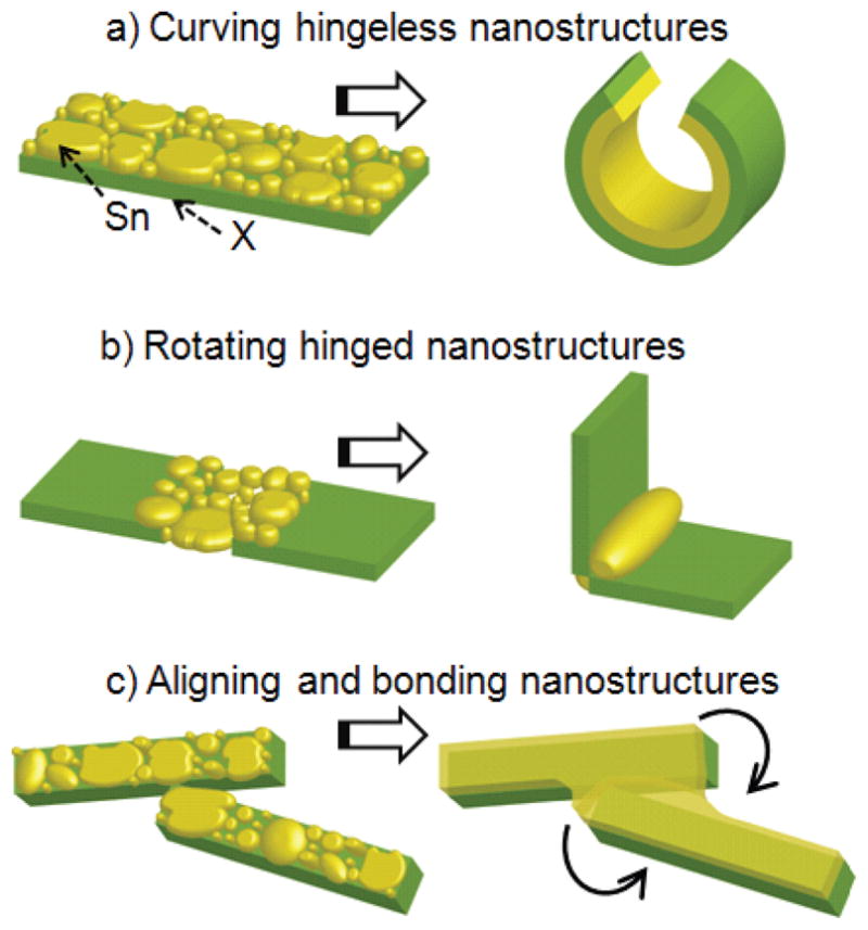
Conceptual schematic diagram of the utility of surface forces to (a) curve hingeless structures, (b) rotate hinged structures, and (c) align and bond nanoscale panels.
Experimental Section
Details of experiments
All nanostructures were first patterned in 2D on silicon (Si) substrates using e-beam lithography. E-beam patterning was achieved using a commercial polymethyl methacrylate (PMMA, 950K-A2) resist, which was spin coated on the substrate. The thickness of the resist was 60 nm and 110 nm for 100 nm and 500 nm cubic structures, respectively. After spinning PMMA, the substrate was baked at 185 °C for 3 minutes. Using an e-beam, the resist was patterned and then developed with an MIBK developer (1:3 = MIBK:IPA) for 30 and 35 seconds for 60 nm and 110 nm thick PMMA layers, respectively. The metallic thin films were deposited by thermal evaporation at around 10−5 Torr; the thickness reported was measured in situ using a quartz crystal. Typically, a 0.2 nm thick adhesion promoting chromium (Cr) layer was deposited before metal panel deposition. Alumina (Al2O3) films were deposited by e-beam deposition at around 2×10⁻⁶ Torr without any adhesion layer. Typically, Al2O3 adhered well on Si substrates. A second step of e-beam lithography was performed in a similar manner to the first layer and the required thickness of hinge material Sn was thermally evaporated. After deposition, lift-off was achieved by dissolution of the PMMA resist in acetone. In all cases, self-assembly was achieved in a plasma etcher using a 25 W RF plasma power, and on removal from the etcher, the nanostructures were held in place. The heat required to reflow Sn was generated during release of the panels from the Si substrate by plasma etching with 12 sccm carbon tetrafluoride (CF4) and 3.6 sccm oxygen (O2) gas. The dependence of Sn reflow on the plasma etch conditions are described in detail elsewhere.32–33
Fabrication of curved hingeless structures composed of a metal-metal bilayer
E-beam lithography and lift-off metallization were utilized to pattern solid tin (Sn) and nickel (Ni) films. Only one layer of e-beam patterning was needed. First, 0.2 nm thick Cr was deposited on PMMA patterns. This was followed by Ni deposition. Sn was then deposited atop the Ni. All the metals were deposited using thermal evaporation.
Fabrication of hinged polyhedra composed of metallic faces and metallic hinges
Experimental details are similar to those described for the curved structures, except that we used a second layer of e-beam lithography to deposit Sn only within hinge regions. We also explored a single layer patterning process that is described later.
Fabrication of hinged polyhedra composed of dielectric faces, metallic hinges and gold patterns
Here, three layers of e-beam lithography were used to first define a pattern within a gold (Au) layer. The second layer was used to pattern the dielectric Al2O3 panels and a third layer was used to deposit Sn within the hinge regions.
Results and Discussion
While it is true that much of our inspiration for nanoscale assembly was derived from earlier work on meso- and microscales, several challenges emerged at the nanoscale. Thin films had to be deposited and patterned with sub-100 nm length scales. We utilized a lift-off process coupled with high resolution e-beam patterning of PMMA. Our assembly schemes often required two or more layers of e-beam patterning with nanoscale alignment between layers. At these small sizes, the sizes of individual grains become comparable to the hinge dimensions, so an optimization of the thin film deposition process was necessary to enable patterning of hinges. Our choice of materials was based on several factors. The choice of the sacrificial layer was motivated by ease of processing and etching selectivity; we utilized a Si substrate which also functioned as the sacrificial layer. Our choices for hinge and panel compositions were based on intermediate surface wetting between the two materials so that a grain deposition of the hinge was observed and the hinge material did not have a strong tendency to wet the panel surface. At the nanoscale, we observed that Sn/Ni and Sn/Al2O3 fulfill this criterion, and it is likely that other hinge/panel combinations exist. In general, a low melting point hinge material is desired to enable relatively low temperature assembly. For nanoscale assembly, we utilized Sn which has a bulk melting point of 232 °C.
Fabricating curved hingeless nanostructures using surface forces
Surface forces associated with coalescence and liquefaction of metallic Sn grains can be used to curve bilayer nanostructures (Fig. 3). Here, the coalescence of Sn grains generates a differential stress in the bilayer that is consistent with a reduction in the Sn film dimensional length. This stress causes the bilayer to rotate such that the Sn film is on the inner surface. The final radius of curvature depends on both the magnitude of the stress generated by the coalescing Sn grains as well as the rigidity of the bilayer. From our experiments, we observed that the radius of curvature depended on the length and width of the cantilever as well as the thickness of coalescing Sn and the underlying panel (Fig. 3a); curved nanostructures with radii as small as 20 nm were assembled.32 The ability to vary radii based on geometric parameters has enabled the fabrication of nanostructures with both homogeneous (rings, hooks, tubes) as well as heterogeneous (spirals and talons) radii of curvature.32 The methodology was utilized to fabricate precisely patterned and simultaneously curved nanostructures such as nanotubes with 10 nm scale arbitrary patterning of letters (Fig. 3b). The advantages of using surface forces are that the approach is relatively straightforward and amenable to a wide range of materials.
Figure 3. Fabricating curved hingeless nanostructures using surface forces.
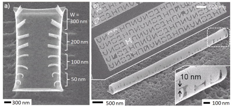
(a) SEM images after assembly showing that cantilevers of different width curve with different radii. All cantilevers in the image had the same length of 500 nm and were composed of a thin film stack with a thickness of approximately 0.2 nm chromium (Cr) adhesion promoter, 5 nm Ni and 2.5 nm Sn. (b) SEM image of an as-patterned 2D panel and the resulting tubular nanostructure. The 2D patterned panel had a composition / thickness of Cr 0.2 nm (adhesion promoter), Ni 5 nm and Sn 5 nm. To demonstrate the versatility and capabilities of the approach, the alphabets NANOJHU were patterned on a tubular nanostructure with a line width resolution of 10 nm.
Fabricating hinged nanostructures using surface forces
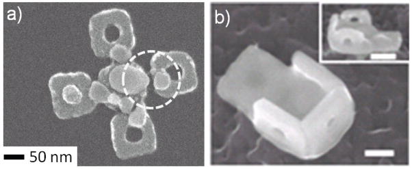
Polyhedral nanostructures composed of metallic (Fig. 4a) or dielectric (Fig. 4b) faces were assembled when Sn was deposited only within hinges. Here, we observed that the minimization of the surface area of the liquefying Sn grains within the hinges generated a torque that caused the panels to rotate. Although we believe this assembly is mechanistically similar to microscale assembly that is described in detail elsewhere, 34–35 further simulations and experiments are needed to explain some interesting nanoscale observations. For example, we observed that the plasma etch conditions could be used to control the rotation angle, 33 presumably due to the extent of heating and grain coalescence. Additionally, the role of grain liquefaction, surface atomic diffusion and coalescence on the self-assembly is more convoluted on the nanoscale. Furthermore, while a bulk melting point can be utilized to rationalize microscale assembly, it is conceivable that the melting point is somewhat depressed and size dependent especially for the sub-50nm sized Sn grains.
Figure 4. Assembly of hinged structures composed of either metallic or dielectric faces.
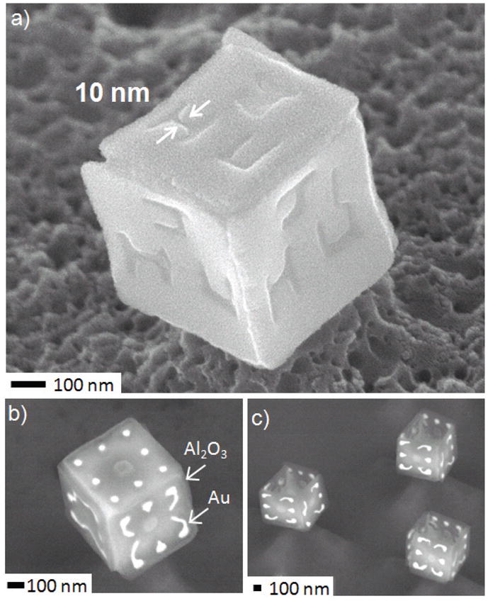
(a) SEM image of a six-faced cube with the letters JHU etched on all faces. Dimensions are approximately: Composition / Thickness: Cr 0.2 nm (adhesion promoter), Ni 38 nm and Sn 49 nm; side length of 500 nm. (b–c) SEM images of dielectric polyhedra composed of alumina faces and metallic gold patterns. The composition / thickness of the films are approximately: Cr 6 nm (adhesion promoter), Au 20 nm, Al2O3 29 nm and Sn 54 nm; side length of 500 nm.
Both five and six faced nanocubes were fabric ated with arbitrary side wall patterns. The patterns shown were either defined in the Ni metal (Fig. 4a) or composed of Au on Al2O3 (Fig. 4b). The patterned Ni polyhedral assembly required two layers of e-beam patterning: one for the Ni panels and one for the Sn hinges. In contrast, the Au/Al2O3 patterned polyhedra required three layers of patterning: one for the Au patterns, a second for the Al2O3 panels and a third to define the Sn hinges. The Au/Al2O3 patterned nanostructures are of especial relevance to electronics, optics and even catalysis. Specifically, for electronics, Al2O3 would function as an electrical insulator and Au as a good conductor; for optics, the permittivities of the two materials are very different in specific regions of the electromagnetic spectrum. Au nanoparticles on Al2O3 supports are also important in catalysis. Dielectric nanoparticles with precise metal patterns in all three dimensions do not exist, and these are the first particles of their kind.
One of the challenges in our methodology for creating nanoparticles using hinged panels is the need for two layers of e-beam lithography with 10–50 nm alignment resolution. Typically, these Ni patterned polyhedra were created by first patterning a PMMA resist with the e-beam and then depositing a thin layer of Ni to form the panels. The PMMA was then dissolved, and a second layer of PMMA was spin coated and patterned to open up the hinge regions, which were filled with Sn. The alignment between the hinge pattern and the panel pattern was critical. Any error in e-beam patterning or lift-off resulted in incorrect assembly. For example, we sometimes observed missing Sn hinges between panels, which resulted in defects associated with non-rotating panels. SEM images of defects in the assembly of 100 and 200 nm side length five faced cubic particles are shown in Fig. 5.
Figure 5.
SEM images showing that (a) a missing hinge defect during 2D patterning results in (b) no rotation of the specific panels in the polyhedra. The image scale bar represents a length of 100 nm and the composition / thickness of the films are approximately: Cr 0.2 nm (adhesion promoter), Ni 13 nm, Sn 26 nm.
To reduce the number of patterning steps, we explored the rotation of hinged panels using a single layer of patterning (Fig. 6). Here, the PMMA resist was patterned and then both Ni and Sn were deposited. We observed that the thickness of the PMMA, Ni and Sn could be optimized to enable the metals to bridge over the PMMA within the hinge gap. This optimization involved decreasing the PMMA thickness while increasing Ni and Sn thickness so that bridging across panels could occur after lift-off metallization. We did indeed observe that rotation of panels was successful whenever the metals bridged the PMMA within the hinge gaps and that this process could enable the self-assembly of nanopyramids. This single layer process is especially attractive for high throughput polyhedral nanoparticle fabrication when patterning is achieved with nanoimprint lithography. The process continues to be optimized to enable high fidelity bridging and rotation of panels.
Figure 6. Assembly of hinged structures using a single e-beam patterning step.
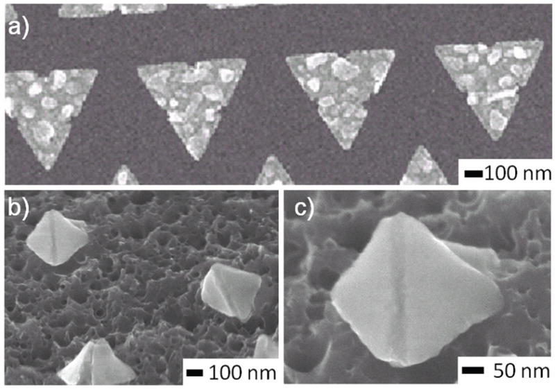
(a) Ni and Sn were deposited after e-beam patterning of a 100 nm thick PMMA resist. The dimensions of the 2D patterns are approximately: Thickness: Cr 0.2 nm, Ni 21 nm, Sn 30 nm and side length 300 nm. (b) When the PMMA resist thickness was optimized so that the metal layers bridged the resist within the hinge, we observed rotation of the panels and pyramidal particles could be formed. (c) Zoomed-in image of one of the pyramidal particles.
There are several parameters that can be tuned to control the rotation angle. We have observed that etch parameters, such as relative concentration of gases, plasma power and etch time, strongly affect grain coalescence, release of the sacrificial layer and hence rotation angles. We have also observed that the thickness (volume) of Sn is important in determining the ultimate fold angle. The precise influence of these parameters continues to be investigated. Moreover, the capacity for liquid drops to self-align at the edges of the panels can also be used to enable high fidelity assembly.
Aligning and bonding panels
In our experiments, we observed that in addition to curving and rotating panels, the liquefying Sn could also be used to align and bond panel edges. This observation is consistent with earlier microscale self-folding results that demonstrate the utility of patterning hinges at the outer edges of the panels, which we have previously referred to as locking hinges. 34–35 On the microscale, we have observed that when the panels rotate and the liquid along the outer edges join, the panels self-align, and are also permanently bonded on subsequent cooling. This self-alignment is similar to that observed in flip-chip bonding. Self-alignment and bonding is driven by the tendency of liquid droplets to fuse, thereby reducing their exposed surface area. On the nanoscale, the energy required to break a liquid drop into smaller drops is very large; for example, orders of magnitude greater than gravitational forces. Hence, nanoscale panels are securely held together by liquefying or coalescing Sn grains and resist coming apart; on cooling, the grains solidify and the panels remain well-bonded.
In microscale assembly of complex polyhedra such as dodecahedra, which are composed of 12 panels, locking hinges are absolutely necessary to provide self-correction since it is challenging to target the required panel rotation angle of approximately 63.4 degrees with absolute precision.35 The bonding of liquid drops at locking hinges also seals the polyhedra and greatly increases their mechanical strength. While the inclusion of locking hinges has greatly enhanced yield of microscale polyhedral assembly, they have been challenging to pattern reproducibly at the nanoscale since we typically size them at approximately one half the rotating hinge width. Based on microscale design rules, 34 the required width of a locking hinge for a 100 nm sized polyhedra is less than 25 nm. Nevertheless, at the nanoscale, we have observed that coalescing Sn grains bridged and bonded adjacent panels (Fig. 7).
Figure 7.
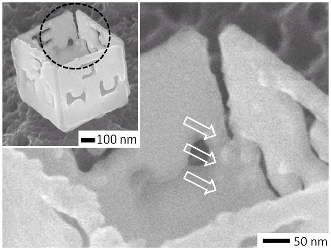
In addition to rotation, alignment and bonding of liquefying Sn grains at the edges between panels results in permanently bonded structures. The arrows point to regions where Sn has bridged and bonded the edges of adjacent panels. In microscale self-assembly, the inclusion of locking hinges at the edges of the panels resulted in enhanced yields and robust assembly.
With regard to material composition, based on our prior microscale assembly efforts, we believe that these nanoscale assembly strategies can be utilized with a wide range of material compositions for both panels and hinges. Here, on the nanoscale, we have demonstrated the incorporation of panels composed of both metals and dielectrics, as well as the construction of two kinds of polyhedra. Previously published surface energy calculations 34 show that such assembly would also be possible with polymeric hinges, since surface forces dominate at small size scales. Experimentally, we have validated this prediction by the assembly of all-polymeric sub-mm scale patterned polyhedra using hinged assembly (Fig. 8). These structures are composed of SU-8 panels and poly(ε-caprolactone) (PCL) hinges; self-assembly was driven by liquefaction of the PCL hinges. Such all-polymer assembly has yet to be achieved on the nanoscale, mainly because it was challenging to plasma etch the Si without also etching the polymers, using our current equipment capabilities. However, we are not aware of any obstructive factors that would prevent such patterning, once a compatible etch, release and patterning process is developed. The fabrication of precisely patterned polymeric nanostructures presents a major opportunity for biomedical engineering since many of these polymers are biocompatible and can be utilized in diagnostics and drug delivery. Here, precise surface patterning can enable recognition for targeting.
Figure 8.
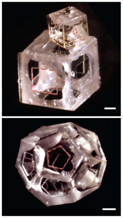
Optical images of all-polymeric sub-mm scale polyhedra self-assembled from a 2D template composed of SU-8 panels and PCL hinges. Scale bars are 250 μm; pores are outlined using red dotted lines to highlight surface patterning. The all-polymeric 2D panels had both rotating and locking hinges. (a) Isotropically patterned six-faced polymer cubes. The cube on top has a 500 μm side length and 73 μm squared pores while the cube on the bottom has a 1 mm side length and a single 500 μm squared pore on each face. (b) 500 μm side length dodecahedron, with 250 μm side length pentagonal pores on each face. We wish to emphasize that unlike the other 3D patterned structures described in the paper, these structures have sub-mm (and not nano) scale dimensions. We believe that it will be possible to scale the assembly of all-polymeric structures down to the nanoscale once the required 2D patterned templates can be fabricated.
Conclusion
We described methodologies to enable 3D patterned nanofabrication by utilizing forces generated when liquefying metals minimize their surface energy. The assembly methodology is highly parallel and versatile. However, our throughput was limited by serial e-beam lithographic patterning in 2D. One could envision using parallel 2D patterning methods such as imprint lithography. However, multilayer alignments with accuracy below 1 micron are challenging to achieve using imprint lithography. Multilayer patterning with different materials is required for heterogeneous integration. For example, the dielectric polyhedra with metal patterns described in this paper required three layers of e-beam lithography. Strategies to enable high throughput, multilayer 2D nanopatterning continue to be addressed by the engineering community, and this is an ongoing challenge in itself. Nevertheless, the essential message we wish to leave the reader with is that irrespective of the 2D nanopatterning methodology implemented, forces that result from a minimization of surface energy can be used to curve or rotate precisely patterned 2D multilayer structures, as well as self-align and permanently bond edges, to create mechanically robust 3D patterned nanostructures and nanoparticles with considerable material versatility.
References
- 1.Somorjai GA. Introduction to Surface Chemistry and Catalysis. 1. Wiley-Interscience; 1994. [Google Scholar]
- 2.Adamson A, Gast AP. Physical Chemistry of Surfaces. 6. Wiley-Interscience; 1997. [Google Scholar]
- 3.Ball P. Shapes: Nature’s Patterns: A Tapestry in Three Parts. 1. Oxford University Press; 2009. [Google Scholar]
- 4.Miller LF. IBM J Res Dev. 1969;13:239–250. [Google Scholar]
- 5.Wale MJ, Edge C, Randle FA, Pedder DJ. Proc. 15th Eur. Conf. Optical Comm. 1989:368–371. [Google Scholar]
- 6.Syms RRA, Yeatman EM. Electronics Lett. 1993;29:662–664. [Google Scholar]
- 7.Goumiri L, Joud JC. Acta Met. 1982;30:1397–1405. [Google Scholar]
- 8.IAPWS Release on Surface Tension of Ordinary Water Substance. International Association for the properties of water and steam, September 1994.
- 9.Schonhorn H, Sharpe LH. J Polym Sci, Part A: Polym Chem. 1965;3:569–573. [Google Scholar]
- 10.Gracias DH, Kavthekar V, Love JC, Paul KE, Whitesides GM. Adv Mater. 2002;14:235–238. [Google Scholar]
- 11.Gimi B, Leong T, Gu Z, Yang M, Artemov D, Bhujwalla ZM, Gracias DH. Biomed Microdevices. 2005;7:341–345. doi: 10.1007/s10544-005-6076-9. [DOI] [PubMed] [Google Scholar]
- 12.Kim E, Whitesides GM. Chem Mater. 1995;7:1257–1264. [Google Scholar]
- 13.Terfort A, Bowden N, Whitesides GM. Nature. 1997;386:162–164. [Google Scholar]
- 14.Bowden N, Terfort A, Carbeck J, Whitesides GM. Science. 1997;276:233–235. doi: 10.1126/science.276.5310.233. [DOI] [PubMed] [Google Scholar]
- 15.Clark TD, Tien J, Duffy DC, Paul KE, Whitesides GM. J Am Chem Soc. 2001;123:7677–7682. doi: 10.1021/ja010634l. [DOI] [PubMed] [Google Scholar]
- 16.Py C, Reverdy P, Doppler L, Bico J, Roman B, Baroud CN. Phys Rev Lett. 2007;98:156103, 4. doi: 10.1103/PhysRevLett.98.156103. [DOI] [PubMed] [Google Scholar]
- 17.Daniel MC, Astruc D. Chem Rev. 2004;104:293–346. doi: 10.1021/cr030698+. [DOI] [PubMed] [Google Scholar]
- 18.Park S, Lim JH, Chung SW, Mirkin CA. Science. 2004;303:348–351. doi: 10.1126/science.1093276. [DOI] [PubMed] [Google Scholar]
- 19.Gu Z, Chen Y, Gracias DH. Langmuir. 2004;20:11308–11311. doi: 10.1021/la047937o. [DOI] [PubMed] [Google Scholar]
- 20.Gu Z, Ye H, Smirnova D, Small D, Gracias DH. Small. 2006;2:225–229. doi: 10.1002/smll.200500296. [DOI] [PubMed] [Google Scholar]
- 21.Chau R, Kavalieros J, Roberds B, Schenker R, Lionberger D, Barlage D, Doyle B, Arghavani R, Murthy A, Dewey G. Technical Digest - International Electron Devices Meeting. 2000:45–48. [Google Scholar]
- 22.Chou SY, Krauss PR, Renstrom PJ. Science. 1996;272:85–87. [Google Scholar]
- 23.Langford RM, Nellen PM, Gierak J, Fu Y. MRS Bull. 2007;32:417–423. [Google Scholar]
- 24.Sudipta R. J Phys D: Appl Phys. 2007;40:R413–R426. [Google Scholar]
- 25.Gates BD, Xu Q, Love JC, Wolfe DB, Whitesides GM. Annu Rev Mater Sci. 2004;34:339–372. [Google Scholar]
- 26.Taur Y, Ning TH. Fundamentals of Modern VLSI Devices. 2. Cambridge University Press; 2009. [Google Scholar]
- 27.Shelby RA, Smith DR, Schultz S. Science. 2001;292:77–78. doi: 10.1126/science.1058847. [DOI] [PubMed] [Google Scholar]
- 28.Rossmann MG, Arnold E, Erickson JW, Frankenberger EA, Griffith JP, Hecht HJ, Johnson JE, Kamer G, Luo M, Mosser AG, Rueckert RR, Barbara S, Gerrit V. Nature. 1985;317:145–153. doi: 10.1038/317145a0. [DOI] [PubMed] [Google Scholar]
- 29.Andersson S. Z Anorg Allg Chem. 2008;634:2161–2170. [Google Scholar]
- 30.Breen TL, Tien J, Oliver SRJ, Hadzic T, Whitesides GM. Science. 1999;284:948–951. doi: 10.1126/science.284.5416.948. [DOI] [PubMed] [Google Scholar]
- 31.Gracias DH, Tien J, Breen TL, Hsu C, Whitesides GM. Science. 2000;289:1170–1172. doi: 10.1126/science.289.5482.1170. [DOI] [PubMed] [Google Scholar]
- 32.Cho JH, James T, Gracias DH. Adv Mater. 2010 doi: 10.1002/adma.200904410. [DOI] [PMC free article] [PubMed] [Google Scholar]
- 33.Cho JH, Gracias DH. Nanolett. 2009;9:4049–4052. doi: 10.1021/nl9022176. [DOI] [PMC free article] [PubMed] [Google Scholar]
- 34.Leong TG, Lester PA, Koh TL, Call EK, Gracias DH. Langmuir. 2007;23:8747–8751. doi: 10.1021/la700913m. [DOI] [PubMed] [Google Scholar]
- 35.Filipiak DJ, Azam A, Leong TG, Gracias DH. J Micromech Microeng. 2009;19:075012. doi: 10.1088/0960-1317/19/7/075012. 6 pp. [DOI] [PMC free article] [PubMed] [Google Scholar]


