Abstract
A critical element in the formation of scaffolds for tissue engineering is the introduction of concentration gradients of bioactive molecules. We explored the use of poly(ethylene glycol) (PEG) microspheres fabricated via a thermally induced phase separation to facilitate the creation of gradients in scaffolds. PEG microspheres were produced with different densities (buoyancies) and centrifuged to develop microsphere gradients. We previously found that the time to gelation following phase separation controlled the size of microspheres in the de-swollen state, while crosslink density affected swelling following buffer exchange into PBS. The principle factors used here to control microsphere densities were the temperature at which the PEG solutions were reacted following phase separation in aqueous sodium sulfate solutions and the length of the incubation period above the ‘cloud point’. Using different temperatures and incubation times, microspheres were formed that self-assembled into gradients upon centrifugation. The gradients were produced with sharp interfaces or gradual transitions, with up to five tiers of different microsphere types. For proof-of-concept, concentration gradients of covalently immobilized proteins were also assembled. PEG microspheres containing heparin were also fabricated. PEG-heparin microspheres were incubated with fluorescently labeled protamine and used to form gradient scaffolds. The ability to form gradients in microspheres may prove to be useful to achieve better control over the kinetics of protein release from scaffolds or to generate gradients of immobilized growth factors.
Keywords: microsphere, hydrogel, gradient, heparin, protein
Introduction
Concentration gradients of signaling molecules are important in embryogenesis, wound healing, immunity, angiogenesis, and nerve cell signaling [1-12]. Therefore, introducing gradients of bioactive signals into scaffolds according to some spatial blueprint may be crucial to the engineering of tissues or organs. In particular, chemotaxis, the preferential movement of cells up a concentration gradient of signaling molecules, is known to be dependent upon the steepness of a concentration gradient as opposed to the average concentration of the molecule [5-7]. This may have particular importance in the development of scaffolds for nerve regeneration. Shoichet et al., have demonstrated that concentration gradients of nerve growth factor immobilized on a scaffold can be used to enhance the directionality of extending dendrites [4, 6]. Bellamkonda et. al., showed that gradients of laminin-1 could also turn growing dorsal root ganglia towards the increasing concentration and gradients of laminin-1 and nerve growth factor could promote regeneration of the sciatic nerve in rats [13, 14].
Scaffolds formed from hydrogels made of synthetic polymers show significant promise in regenerative medicine [15-17]. Biological functions, such as cell adhesion or cell-initiated degradability, may be incorporated within these hydrogels using functional peptides or proteins [2, 16, 18-20]. However, bulk hydrogel scaffolds are typically homogenous structures without macroporosity or spatial organization, much different than native tissue. Modular strategies to produce heterogeneous scaffolds from hydrogel microparticles show promise in addressing these limitations [21, 22].
A number of systems have been used to produce gradients in scaffolds, including pulsatile application of picoliters of growth factor solutions, diffusion of molecules into a gel, and gradient makers in which polymerizing solutions exit two different chambers in varying ratios [1, 4, 5, 10]. However, these methods have distinct disadvantages, such as scaling issues and difficulty in pumping polymerizing solutions. Assembling different types of microparticles in a modular manner may provide the versatility necessary to engineer the properties of bioactive scaffolds, including formation of gradients [16, 22-25]. Mechanical microparticle production techniques (e.g. micromolding, microfluidics, 3D printing, etc.), which are most common, may have scalability issues, as even small scaffolds can require billions of microparticles to form [16, 25-28]. Previously, we have fabricated PEG hydrogel microspheres in solution via a thermally induced phase separation [16]. The microspheres were produced by reacting multi-arm PEG derivatives in the presence of kosmotropic salts that induced a phase separation upon incubation at 37°C or above. The method can be performed rapidly and at large scales. Different functionalities, such as cell adhesion, degradability, and drug delivery, have already been imparted to these microspheres as well [16].
The current study explored how to engineer gradients into scaffolds made from these PEG microspheres. We have found that varying the temperature of the phase separation and the amount of time the PEG is allowed to react above the cloud point allows us to control both the size and the density (buoyancy) of the microspheres. The size of microspheres in their de-swollen state is controlled primarily by the time to reach the gel point, while the swelling following buffer exchange into PBS is determined by crosslink density [29]. The swelling of the microsphere should greatly affect the density of the microspheres by changing the ratio of solvent to polymer. By incubating batches of microspheres for different amounts of time, a range of densities can be produced. The formation of scaffolds from the microspheres is enhanced by centrifugation, exploiting small density differences to introduce gradients while simultaneously crosslinking the microspheres together to form a scaffold. Proteins can be covalently bound to the microspheres or electrostatically attached using heparin in varying concentrations to form concentration gradients of those proteins. The methods described herein may allow for the development of gradient-containing scaffolds for a variety of tissue engineering and drug delivery applications.
Materials and Methods
Unless otherwise noted, all reagents were purchased from Sigma-Aldrich.
PEG Synthesis and Labeling
Eight-arm PEG-OH (PEG8-OH; mol. Wt. 10,000; Shearwater Polymers, Huntsville, AL) was used to synthesize PEG8-vinylsulfone (PEG8-VS) and PEG8-amine as previously described [30]. PEG macromonomers were dissolved separately at 200 mg/mL in Dulbecco’s phosphate buffered saline (PBS; 8 mM sodium phosphate, 2mM potassium phosphate, 140 mM sodium chloride, 10mM potassium chloride, pH 7.4) and sterile filtered with 0.22 μm syringe filters (Millipore). Dylight-488 NHS-ester (Pierce), Dylight-633 NHS-Ester (Pierce), and Dylight-549 Maleimide (Pierce) were dissolved in dimethyl formamide at 10 mg/mL and added to the PEG8-amine solutions at 1600:1, 20:1, or 200:1 mol:mol ratios, respectively, and incubated at 25°C overnight protected from light.
Microsphere Formation
Labeled or unlabeled PEG8-amine solutions were combined with PEG8-VS solutions at a 1:2 ratio. If the solutions were to be used for microsphere formation at 37°C, the solutions were pre-reacted at 37°C for 5-6 hours until a mean dPCS = 100 nm was observed by dynamic light scattering [16]. The PEG solutions (pre-reacted or otherwise) were diluted to 20 mg/mL PEG with PBS and 1.5 M sodium sulfate (in PBS) to a final sodium sulfate concentration of 0.6 M. The PEG8-VS/PEG8-amine solutions were then incubated above the cloud point at 37°C, 70°C, or 95°C for various times (Figure 1). Suspensions of microspheres were subsequently buffer exchanged into PBS 2x to remove the sodium sulfate by: (1) diluting the microsphere solution 3:1 with PBS and titurating, (2) centrifuging at 14,100g for 2 min, (3) removing the supernatant.
Figure 1. Microsphere Formation.

Gradient Formation
The glass walls of Pasteur pipettes were passivated with PLL(375)-g[7]-PEG(5) [31, 32]. The pipettes were filled with a 20 mg/mL PLL-g-PEG solution, incubated for 30 seconds, and washed with DI water. After sufficient drying time, the tips of the pipettes were sealed with silicone aquarium sealant (DAP Inc., Baltimore, MD). To form scaffolds, the microspheres were resuspended in 10% Fetal Bovine Serum in DMEM (Invitrogen) after the final PBS wash and combined with other labeled microsphere solutions in the Pasteur pipette. The pipette was placed in a 15 mL conical vial and centrifuged at 1000g for 10 min and then incubated overnight at 37°C before viewing (Figure 2).
Figure 2. Gradient formation.
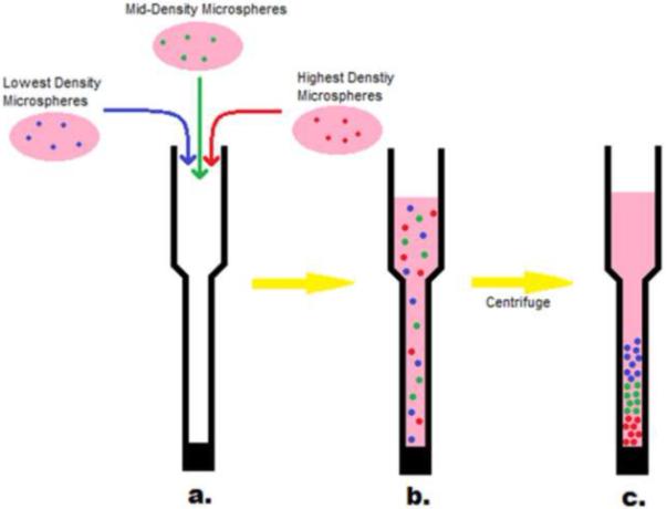
(a) Microspheres with the same chemical structure but with different densities were produced from PEG precursors labeled with different fluorescent dyes. The microspheres were suspended in 10% serum and added to a PLL-g-PEG treated Pasteur pipette. (b) The microspheres were initially well mixed. (c) Upon centrifugation, the microspheres separated based on their relative densities.
Confocal microscopy
Fluorescence microscopy was performed with a Nikon Eclipse C1/80i confocal microscope. Microsphere gradients were imaged while still in the Pasteur pipettes with a 10X objective (0.30 DIC L WD 7.4). Multiple images were taken along the length of the pipette and processed using EZ-C1 3.70 FreeViewer software (Nikon Instruments Inc.) and then combined.
GDNF labeling
Recombinant human glial cell line-derived neurotrophic factor (100 μg/mL, GDNF, R&D Systems, Minneapolis, MN) was reconstituted in PBS. Dylight-488 was added to the solution for a final concentration of 50 μg/mL and incubated overnight at room temperature. Cysteine (200 μg/mL) was added and incubated overnight as well. Bovine serum albumin (0.1%; BSA) was then added to the solution to reduce adsorption to the vials. SDS-PAGE showed that while BSA did receive a small amount of labeling, the much smaller quantity of GDNF was labeled to a much greater extent (See Supplemental Figure 1). (Note: For the covalent attachment of GDNF at 37°C, cysteine was not added, and the BSA was revealed by SDS-PAGE to have become significantly labeled.)
Protein attachment to microspheres
The labeled GDNF/BSA solution was diluted by half in PBS and added in place of the PBS along with the sodium sulfate solution and unlabeled PEG solutions (pre-reacted or otherwise). The combined solution was then incubated and washed as before to form microspheres.
Heparin attachment
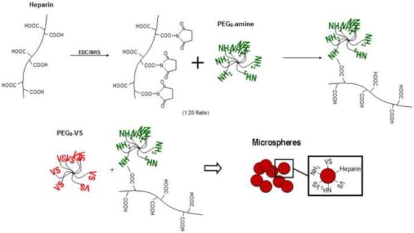
A solution of 500 mM N-(3-Dimethylaminopropyl)-N’-ethylcarbodiimide hydrochloride (EDC), 200 mM N-Hydroxy-succinimide (NHS), and 50 mg/mL heparin sodium salt (mol. wt. ~18,000) in MES buffer (10 mM, pH 6.0) was incubated at room temperature for 30 minutes. The activated heparin solution was then added to a 200 mg/mL solution of PEG8-amine at a 20:1 PEG8-amine to heparin mol:mol ratio and incubated at room temperature for another 30 minutes before refrigeration. Microspheres were formed as before using the heparin-conjugated PEG8-amine along with PEG8-VS in a 1:2 ratio (Figure 3).
Figure 3. Heparin Attachment.
Protamine Labeling
Protamine sulfate salt from salmon (10 mg/mL, Grade X) was dissolved in 50 mM sodium borate buffer (pH 8.5). Dylight-488 was added to the solution for a final concentration of 50 μg/mL and incubated overnight at room temperature. As before, a PD-10 Sephadex G-25M column (Supelco, Bellefonte, PA) was used to remove any unbound Dylight-488. The column was washed with ~20 mL PBS before adding the labeled protamine solution. After the sample entered the column, 2.4 mL of PBS was added and allowed to flow through. The labeled protamine was eluted with 20 mL PBS, and the flow through was collected in 0.5-0.75 mL fractions. The fluorescence of each fraction was measured with a fluorometer and the protein-containing fraction with peak fluorescence was retained. The final concentration of labeled protamine in the peak fraction was ~1 mg/mL.
Protamine Attachment to Heparin Microspheres
After the PBS washes, the microspheres were spun down, and the supernatant was removed. The labeled protamine solution was diluted to 25 μg/mL in PBS and added to the dehydrated microspheres. The microspheres were incubated with the protamine solution at room temperature overnight.
Results
Density measurements of microspheres with Histopaque-1077 and Histopaque-1119 demonstrated that microspheres under all formation conditions migrated to the interface of the two solutions. This showed that all the microspheres had specific gravities between 1.077 and 1.119. Thus density differences across the spectrum of formation conditions were quite subtle. To determine if the density differences between microspheres were sufficient to generate microsphere gradients, PEG8-amine was fluorescently labeled using one of three different dyes and used to form microspheres with different densities. In all of the experiments presented here, microspheres in any one scaffold were formed at the same temperature (37, 70 or 95°C) but incubated above the cloud point for different lengths of time. Microspheres with different densities were centrifuged together in the presence of 10% serum to form scaffolds (we previously demonstrated that microspheres crosslink together in the presence of serum proteins to form solid materials) [16]. The distribution of the fluorescent dyes in the scaffold was visualized using a scanning confocal fluorescence microscope.
The scaffolds were formed in the bottoms of Pasteur pipettes. Each scaffold was about 2 cm long. The glass walls provided a good optical platform for the scanning confocal microscopy. However, early experiments showed substantial streaking of microspheres along the walls of the pipette. Evidently, some microspheres were adhering to the glass walls and not migrating properly. The presence of amines in the microspheres makes them net cationic, [29] probably promoting adhesion to the anionic silanol groups on the glass. The glass was thus coated with PLL-g-PEG to prevent the microspheres from adhering to the glass walls. This eliminated the streaking of microspheres and allowed the formation of distinct gradients.
We found that incubation of the PEG at 70°C provided the greatest range and control of densities of the microspheres while the keeping the polydispersity to a minimum. To demonstrate the full range of densities, a two-tier scaffold was made using the highest and the lowest density microspheres (Figure 4). The incubation times above the cloud point used to produce these two types of microspheres were 11 and 45 minutes. Times less than 11 minutes did not produce microspheres. Times greater than 45 minutes led to the aggregation of the microspheres into a gel-like structure.
Figure 4. Two-tier gradient with sharp interface.
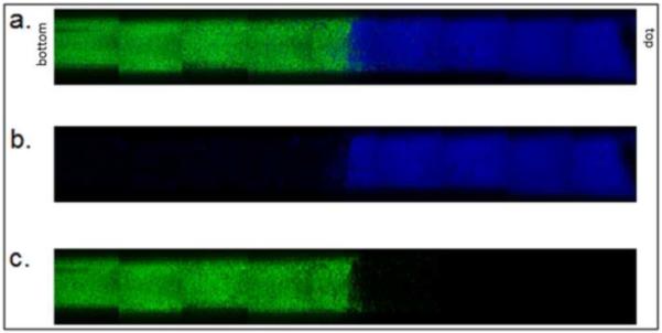
Microspheres were formed above the cloud point at 70°C in 0.6 M sodium sulfate solution. Dylight-488 (green) labeled microspheres were incubated above the cloud point for 45 minutes. Dylight-633 (blue) labeled microspheres incubated above the cloud point for 11 minutes. (a) Combined channels, (b) blue only, (c) green only.
Next, we determined how many tiers with sharp interfaces could be produced in these scaffolds. The maximum number of clearly defined tiers of microspheres that we were able to form was three (Figure 5). We previously showed a nonlinear relationship between density, and incubation time, with large changes in swelling (and presumably density) soon after microspheres begin to form, but with a long plateau with a slow rate of change in swelling at longer incubation times [29]. Incubation times resulting in well defined 3-tier gradient were 11, 17, and 45 minutes. If we tried to achieve more than three tiers, the tiers began to blend together. This blending, however, could be useful if gradual transitions between levels were desired, so we formed 5-tier gradients as well (Figure 6). The best incubation times for forming 5-tiered gradient scaffolds were 11, 12, 16, 26, and 45 minutes. In this 5-tier gradient, the transitions from level to level became nearly seamless.
Figure 5. Three-tier gradient with sharp interfaces.
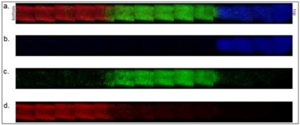
Microspheres were formed above the cloud point at 70°C. Dylight-488 (green) labeled microspheres were incubated above the cloud point for 45 minutes. Dylight-549 (red) labeled microspheres were incubated above the cloud point for 17 minutes. Dylight-633 (blue) labeled microspheres were incubated above the cloud point for 11 minutes. (a) Combined channels, (b) blue only, (c) green only, (d) red only.
Figure 6. Five-tier gradient.

Microspheres were formed above the cloud point at 70°C. Dylight-488 (green) labeled microspheres were incubated above the cloud point for 12 or 45 minutes. Dylight-549 (red) labeled microspheres were incubated above the cloud point for 16 minutes. Dylight-633 (blue) labeled microspheres were incubated above the cloud point for 11 or 26 minutes. (a) Combined channels, (b) blue only, (c) green only, (d) red only.
Though this 5-tier gradient may provide great control over the form of the gradient, a simple 2-tier gradient with a gradual transition between levels might also be desirable. At the standard 70°C formation temperature, either two distinct layers or no detectable gradient were formed. Exploring another temperature (95°C) resulted in more success. The higher temperature resulted in microspheres with densities different enough to separate into tiers but close enough to have a region with substantial overlap. We found the most successful incubation times at 95°C for a gradual transition two-tier gradient were 3 and 5 minutes (Figure 7).
Figure 7. Two-tier gradient with gradual transition.

Microspheres were formed above the cloud point at 95°C. Dylight-488 (green) labeled microspheres were incubated above the cloud point for 5 minutes. Dylight-633 (blue) labeled microspheres were incubated above the cloud point for 3 minutes. (a) Combined channels, (b) blue only, (c) green only.
We are particularly interested in producing conduits for nerve regeneration, and GDNF has been shown to enhance motor nerve regeneration [33, 34]. To directly visualize the GDNF in the scaffolds, we fluorescently labeled the protein with Dylight-488. After overnight reaction, BSA was added to reduce adsorption to the walls of the vials. However, some of the BSA also became labeled, so the solution contained a mixture of the two proteins, as later detected by SDS-PAGE. The labeled protein mixture demonstrated that covalent coupling of proteins to the microspheres did not interfere with gradient formation. A simple two tier gradient of Dylight-488 labeled GDNF was made using the two tier gradient scheme that produced sharp interfaces. The denser microspheres were formed in the presence of the fluorescently labeled proteins to promote covalent attachment. The less dense microspheres were labeled with Dylight 633 so that these microspheres could be visualized in the scaffold. Covalent coupling of proteins to one of the microsphere types did not affect gradient formation (Figure 8).
Figure 8. Two-tier gradient with covalently coupled GDNF.

Microspheres were formed above the cloud point at 70°C. Dylight-488 (green) labeled GDNF was covalently coupled to PEG precursors during microsphere formation. The PEG/protein microspheres were incubated above the cloud point for 45 minutes (dye is covalently coupled to protein). Dylight-633 (blue) labeled microspheres were incubated above the cloud point for 11 minutes (no protein is coupled; dye is covalently coupled to PEG precursor). (a) Combined channels, (b) blue only, (c) green only.
Due to the high temperature of microsphere formation (70°C), the proteins were likely denatured. At physiological temperature, 37°C, the only gradients that were produced were two tier gradients with gradual transitions between levels (Figure 9). The incubation times above the cloud point for forming the 2-tier gradient at physiological temperature were 20 and 65 minutes. As before, the denser microspheres were formed in the presence of the labeled protein to ensure covalent attachment, while the lighter microspheres were labeled with Dylight 633.
Figure 9. Two-tier gradient with covalently coupled BSA/GDNF formed at 37°C.

Microspheres were formed above the cloud point at 37°C. Dylight-488 (green) labeled BSA/GDNF was covalently coupled to PEG precursors during microsphere formation. The PEG/protein microspheres were incubated above the cloud point for 65 minutes (dye is covalently coupled to protein). Dylight-633 (blue) labeled microspheres were incubated above the cloud point for 20 minutes (no protein coupled, dye bound to PEG precursor). (a) Combined channels, (b) blue only, (c) green only.
An alternative to covalent bonding is to use heparin to promote electrostatic binding of heparin-binding proteins [35-37]. Heparin-binding proteins potentially could be bound after microsphere formation, allowing microsphere formation at high temperatures, but eliminating the risk of protein denaturation. Non-covalent coupling would also prevent the reduction in activity that covalent binding might cause. To attach heparin to the microspheres, we activated carboxyl groups on heparin with EDC and NHS and reacted this with PEG8-amine, similar to the chemistry used by Tae, et al [37]. The microspheres were formed as before using the PEG8-amine with covalently coupled heparin at 70°C or 95°C, allowing the use of the most versatile gradient-formation protocols. A three tier gradient of heparin-decorated microspheres with sharp interfaces is shown (Figure 10).
Figure 10. Three-tier gradient with PEG/heparin microspheres.
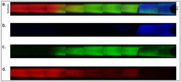
Microspheres were formed above the cloud point at 70°C using heparin-coupled PEG8-amine. Dylight-488 (green) labeled microspheres were incubated above the cloud point for 45 minutes. Dylight-549 (red) labeled microspheres were incubated above the cloud point for 17 minutes. Dylight-633 (blue) labeled microspheres were incubated above the cloud point for 11 minutes. (a) Combined channels, (b) blue only, (c) green only, (d) red only.
To demonstrate that the microspheres were indeed decorated with heparin, we performed a number of controls using Dylight-488 labeled protamine (a protein with very high affinity for heparin). Protamine bound to the formed PEG/heparin microspheres was shown to be non-covalently bound by eluting the protamine at elevated NaCl concentrations (Figure 11). The denser PEG/heparin microspheres were incubated overnight with Dylight-488 labeled protamine and then spun down with lighter Dylight-633 labeled, PEG/heparin microspheres. A gradient of protamine was formed using the sharp, two tier gradient scheme (Figure 12).
Figure 11. High salt release of protamine.
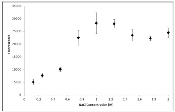
Sodium chloride was added in various concentrations (0 - 2 M) to heparin-decorated PEG microspheres with Dylight-488 labeled protamine bound. After 40 hours the fluorescence of the supernatant was measured to track the release of protamine compared to salt concentration (n=2 for each data point, mean and standard deviation reported for each).
Figure 12. Two-tier gradient with electrostatically bound protamine.
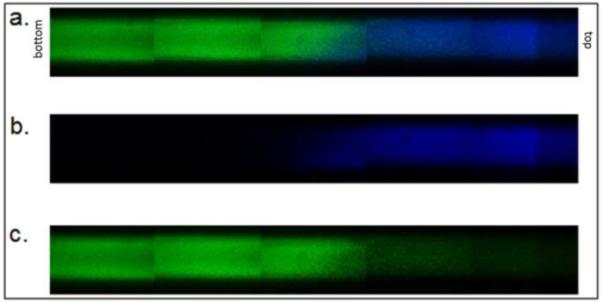
PEG-heparin microspheres were formed above the cloud point at 70°C. PEG-heparin microspheres were incubated above the cloud point for 45 minutes. Following buffer exchange into PBS, microspheres were incubated with Dylight-488 (green) labeled protamine. Dylight-633 (blue) labeled PEG-heparin microspheres were incubated above the cloud point for 11 minutes. (a) Combined channels, (b) blue only, (c) green only.
Discussion
Using differences in microsphere density, multiple tier scaffolds were constructed with sharp or gradual transitions between levels. The two-tiered scaffold with a gradual transition suggested the possibility to produce linear gradients in concentration of cell adhesion peptides/proteins, mechanical stiffness, growth factor/drugs, degradability, etc. Up to five tier gradients were possible. The degree to which a particular property is added to each tier could be controlled independently, such that exponential, parabolic, impulse, and many other gradient profiles may be imagined. In particular, a gradient might be chosen that balances the diffusion out of one or both ends of the scaffolds, producing zero order release [38].
The microsphere gradients were easily produced; however, several challenges remain to translate these properties into a functioning growth factor delivery system. The best results were obtained with microspheres formed at 70°C and 95°C. At 37°C, the widest possible range of incubation times above the cloud point resulted in density differences that could only produce a two-tiered gradient with a gradual transition. The mechanism for this was not determined, but we may speculate based on previous results. We previously demonstrated that following phase separation, the PEG-rich phases coarsen, or increase in size over time due to coalescence. At the gel point, coalescence is halted. Longer gelation times result in larger microspheres. The time to reach the gel point may be decreased by pre-reacting the PEG macromers prior to phase separation or by increasing temperature or pH. After gelation, the microspheres remain in the phase separated state until buffer exchanged into PBS. After buffer exchange, crosslinking may continue, but is likely quite slow due to the lower concentration of PEG in the swollen gel. These are second order reactions, with the reaction rate scaling with the PEG concentration squared (note that the PEG8-vinylsulfone and PEG8-amine are not present at equal concentrations but the same scaling applies). Thus, the number of crosslinks formed in the phase separated state will be critical in determining the degree of swelling following buffer exchange. The relationship between crosslink density and swelling is described by the well-known Flory-Rehner equation [39]. However, we previously found that the decrease in swelling with increasing crosslinking time was not readily described in the Flory-Rehner framework other than qualitatively [29]. Intuitively, one would expect that soon after gelation, the number of crosslinks should increase rapidly. A large number of multiarm-PEGs with two arms attached to the network should be present at the gel point, which soon become crosslink sites after only one more arm attaches to the network (assuming all three arms are elastically active). Later on, however, the formation of crosslink sites will be slowed by steric hindrance. The general shape of the curve provides guidelines for selecting timepoints to achieve gradual transitions between tiers. Close to the gel point, the incubation times must be closely spaced because the density is changing rapidly. At longer times, the incubation times must be spaced further apart. If the incubation times are too close, no separation into layers will be observed, while if they are too far apart, a sharp interface will develop. We found that the production of a gradual transition between two tiers was most successful if the microspheres were formed at 95°C. Gradual transitions may be observed in the 5-tier scaffold made from microspheres formed at 70°C. However, two tiered gradients formed from these microspheres had a transition zone that did not extend throughout the scaffold (data not shown). Due to the shape of the curve that describes swelling as a function of incubation time, finding times that led to a near linear gradient in a two-tiered scaffold may simply have required more trial-and-error, and we most likely were just fortunate to find appropriate times in the 95°C case. We examined the size and polydispersity of microspheres qualitatively and did not observe a striking difference between those formed at 70°C and 95°C, eliminating this as a possible source for the observed difference in gradient formation.
Covalent immobilization at 37°C will be necessary to prevent protein denaturation, but the range of densities that could be generated at this temperature was quite limited. Close examination of the confocal images revealed what appear to be large aggregates of microspheres. According to Stoke’s law, terminal velocity scales with radius squared, providing a mechanism for the aggregates to sediment more rapidly. The presence of aggregates may be related to the long incubation times. However, the aggregates appear to be present in the 37°C microspheres that were incubated above the cloud point for only 20 minutes. Due to the slower reaction kinetics at 37°C, the microspheres formed at this temperature were larger, likely due to a longer time to reach the gel point, despite the fact that the solutions were pre-reacted prior to phase separation. Aggregation may be related to microsphere size, as Stoke’s law also applies to the rising of the larger microspheres in the dense sodium sulfate solutions (‘creaming’). Aggregation thus may have been enhanced as microspheres concentrated near the top of the solution. Microsphere formation is performed in unstirred solutions to minimize coarsening prior to gelation, but this may also enhance aggregation of the formed microspheres that rise to the top of the solution.
The current results suggest that microsphere formation at 70°C or higher has distinct advantages. Notably, it appears that aggregation was minimized due to a combination of small microsphere size and shorter incubation times. For the delivery of growth factors and other proteins, post-loading of the proteins would be necessary. Yet, the small size of the microspheres may make post-loading somewhat difficult. The effective diffusion coefficient of heparin-binding proteins in the presence of immobilized heparin is simply,
where [P] is the concentration of free protein and [B] is the concentration of bound protein [40]. In the presence of an excess of heparin binding sites, this ratio is simply:
where [H] is the concentration of bound heparin. To decrease the effective diffusion coefficient, high affinity interactions or high concentrations of heparin are required. This becomes important due to the small size of the microspheres produced (less than 5 microns in diameter). With microspheres of this size, the time for equilibration with the surrounding solution is quite short (order of seconds). For a Fick number (mass transfer Fourier number) of τ = 0.5, representing about 99% equilibration between the microsphere and the surrounding medium, requires a time of t = τR2/DAB. A typical DAB for a heparin binding growth factor (mol. wt. 20,000 Da) is 1.01 × 10⁻⁴ cm2/min [41]. With a KD of 3 × 10⁻⁷ M [30] and a heparin concentration of 4.6 × 10⁻⁵ M calculated for these microspheres, the time to reach a Fick number of 0.5 is less than 3 seconds. After the microspheres are assembled into a scaffold, the appropriate length scale for diffusion is that of the scaffold and controlled release will occur of over much longer time periods. However, the rapid equilibration presents a challenge for forming gradients by centrifugation, which requires about 10 minutes. To overcome this limitation, the PEG/heparin microspheres were incubated with protamine, which has an extremely high binding affinity for heparin [42, 43]. However, the equations presented above provide a guidepost for engineering the system for growth factor delivery by non-covalent interactions. Another solution may be to incorporate high densities of positive or negative charges into the microspheres, such as are found in gelatin microspheres that are used for growth factor delivery [44, 45]. This may allow the attachment and controlled release of a variety of charged biological molecules.
Conclusions
We have shown that various gradients can be fabricated by manipulating the densities of PEG microspheres. In particular, the five tier gradient could be used to make a wide variety of complex profiles, while the gradual two tier gradient provided a fast and simple way of forming a linear gradient. Using these techniques, a two tier sharp gradient in GDNF was produced. A somewhat linear gradient in GDNF/BSA was formed with microspheres fabricated at a physiological temperature. Heparin was bound to the microspheres to promote attachment of heparin binding molecules post-microsphere formation. The heparin microspheres formed gradients as before, and a two-tiered gradient in protamine was produced. With further engineering, this system may be useful for the development of a variety of gradients in PEG-based scaffolds
Supplementary Material
Acknowledgements
The authors are grateful to Igor Efimov for use of the confocal microscope and funding from NIH R01HL085364 and the Center for Material Innovation at Washington University in St. Louis. We thank Patrick Barranger, Casey Donahoe, Megan Flake, and Amanda Walker for technical assistance.
Footnotes
Competing Financial Interests
The Authors have no competing financial interests.
Publisher's Disclaimer: This is a PDF file of an unedited manuscript that has been accepted for publication. As a service to our customers we are providing this early version of the manuscript. The manuscript will undergo copyediting, typesetting, and review of the resulting proof before it is published in its final citable form. Please note that during the production process errors may be discovered which could affect the content, and all legal disclaimers that apply to the journal pertain.
References
- [1].Cao X, Shoichet MS. Defining the concentration gradient of nerve growth factor for guided neurite outgrowth. Neuroscience. 2001;103:831–40. doi: 10.1016/s0306-4522(01)00029-x. [DOI] [PubMed] [Google Scholar]
- [2].DeLong SA, Moon JJ, West JL. Covalently immobilized gradients of bfgf on hydrogel scaffolds for directed cell migration. Biomaterials. 2005;26:3227–34. doi: 10.1016/j.biomaterials.2004.09.021. [DOI] [PubMed] [Google Scholar]
- [3].Fisher PR, Merkl R, Gerisch G. Quantitative-analysis of cell motility and chemotaxis in dictyostelium-discoideum by using an image-processing system and a novel chemotaxis chamber providing stationary chemical gradients. J Cell Biol. 1989;108:973–84. doi: 10.1083/jcb.108.3.973. [DOI] [PMC free article] [PubMed] [Google Scholar]
- [4].Kapur TA, Shoichet MS. Immobilized concentration gradients of nerve growth factor guide neurite outgrowth. J Biomed Mater Res Part A. 2004;68A:235–43. doi: 10.1002/jbm.a.10168. [DOI] [PubMed] [Google Scholar]
- [5].Knapp DM, Helou EF, Tranquillo RT. A fibrin or collagen gel assay for tissue cell chemotaxis: assessment of fibroblast chemotaxis to grgdsp. Exp Cell Res. 1999;247:543–53. doi: 10.1006/excr.1998.4364. [DOI] [PubMed] [Google Scholar]
- [6].Moore K, Macsween M, Shoichet M. Immobilized concentration gradients of neurotrophic factors guide neurite outgrowth of primary neurons in macroporous scaffolds. Tissue Eng. 2006;12:267–78. doi: 10.1089/ten.2006.12.267. [DOI] [PubMed] [Google Scholar]
- [7].Parent CA, Devreotes PN. A cell’s sense of direction. Science. 1999;284:765–70. doi: 10.1126/science.284.5415.765. [DOI] [PubMed] [Google Scholar]
- [8].Rosoff WJ, Urbach JS, Esrick MA, McAllister RG, Richards LJ, Goodhill GJ. A new chemotaxis assay shows the extreme sensitivity of axons to molecular gradients. Nat Neurosci. 2004;7:678–82. doi: 10.1038/nn1259. [DOI] [PubMed] [Google Scholar]
- [9].Singh M, Morris CP, Ellis RJ, Detamore MS, Berkland C. Microsphere-based seamless scaffolds containing macroscopic gradients of encapsulated factors for tissue engineering. Tissue Eng Part C Methods. 2008;14:299–309. doi: 10.1089/ten.tec.2008.0167. [DOI] [PMC free article] [PubMed] [Google Scholar]
- [10].Song HJ, Ming GL, Poo MM. Camp-induced switching in turning direction of nerve growth cones. Nature. 1997;388:275–9. doi: 10.1038/40864. [DOI] [PubMed] [Google Scholar]
- [11].Song HJ, Poo MM. The cell biology of neuronal navigation. Nat Cell Biol. 2001;3:E81–E8. doi: 10.1038/35060164. [DOI] [PubMed] [Google Scholar]
- [12].Wang XQ, Wenk E, Zhang XH, Meinel L, Vunjak-Novakovic G, Kaplan DL. Growth factor gradients via microsphere delivery in biopolymer scaffolds for osteochondral tissue engineering. J Control Release. 2009;134:81–90. doi: 10.1016/j.jconrel.2008.10.021. [DOI] [PMC free article] [PubMed] [Google Scholar]
- [13].Dodla MC, Bellamkonda RV. Anisotropic scaffolds facilitate enhanced neurite extension in vitro. J Biomed Mater Res A. 2006;78A:213–21. doi: 10.1002/jbm.a.30747. [DOI] [PubMed] [Google Scholar]
- [14].Dodla MC, Bellamkonda RV. Differences between the effect of anisotropic and isotropic laminin and nerve growth factor presenting scaffolds on nerve regeneration across long peripheral nerve gaps. Biomaterials. 2008;29:33–46. doi: 10.1016/j.biomaterials.2007.08.045. [DOI] [PMC free article] [PubMed] [Google Scholar]
- [15].Drury JL, Mooney DJ. Hydrogels for tissue engineering: scaffold design variables and applications. Biomaterials. 2003;24:4337–51. doi: 10.1016/s0142-9612(03)00340-5. [DOI] [PubMed] [Google Scholar]
- [16].Scott EA, Nichols MD, Kuntz-Willits R, Elbert DL. Modular scaffolds assembled around living cells using poly(ethylene glycol) microspheres with macroporation via a non-cytotoxic porogen. Acta Biomater. 2009;6:29–38. doi: 10.1016/j.actbio.2009.07.009. [DOI] [PMC free article] [PubMed] [Google Scholar]
- [17].Tessmar JK, Gopferich AM. Customized peg-derived copolymers for tissue-engineering applications. Macromol Biosci. 2007;7:23–39. doi: 10.1002/mabi.200600096. [DOI] [PubMed] [Google Scholar]
- [18].Almany L, Seliktar D. Biosynthetic hydrogel scaffolds made from fibrinogen and polyethylene glycol for 3d cell cultures. Biomaterials. 2005;26:2467–77. doi: 10.1016/j.biomaterials.2004.06.047. [DOI] [PubMed] [Google Scholar]
- [19].Lutolf MP, Hubbell JA. Synthetic biomaterials as instructive extracellular microenvironments for morphogenesis in tissue engineering. Nat Biotechnol. 2005;23:47–55. doi: 10.1038/nbt1055. [DOI] [PubMed] [Google Scholar]
- [20].Zhang G, Wang XH, Wang ZL, Zhang JY, Suggs L. A pegylated fibrin patch for mesenchymal stem cell delivery. Tissue Eng. 2006;12:9–19. doi: 10.1089/ten.2006.12.9. [DOI] [PubMed] [Google Scholar]
- [21].Khademhosseini A, Langer R. Microengineered hydrogels for tissue engineering. Biomaterials. 2007;28:5087–92. doi: 10.1016/j.biomaterials.2007.07.021. [DOI] [PubMed] [Google Scholar]
- [22].Rivest C, Morrison DWG, Ni B, Rubin J, Yadav V, Mahdavi A, et al. Microscale hydrogels for medicine and biology: synthesis, characteristics and applications. J Mech Mater Struct. 2007;2:1103–19. [Google Scholar]
- [23].Du YA, Lo E, Ali S, Khademhosseini A. Directed assembly of cell-laden microgels for fabrication of 3d tissue constructs. Proc Natl Acad Sci U S A. 2008;105:9522–7. doi: 10.1073/pnas.0801866105. [DOI] [PMC free article] [PubMed] [Google Scholar]
- [24].Serban MA, Prestwich GD. Modular extracellular matrices: solutions for the puzzle. Methods. 2008;45:93–8. doi: 10.1016/j.ymeth.2008.01.010. [DOI] [PMC free article] [PubMed] [Google Scholar]
- [25].Yeh J, Ling YB, Karp JM, Gantz J, Chandawarkar A, Eng G, et al. Micromolding of shape-controlled, harvestable cell-laden hydrogels. Biomaterials. 2006;27:5391–8. doi: 10.1016/j.biomaterials.2006.06.005. [DOI] [PubMed] [Google Scholar]
- [26].Thomas B, Tao X, Brook D, Xiaofeng C. Application of inkjet printing to tissue engineering. Biotechnol J. 2006:910–7. doi: 10.1002/biot.200600081. [DOI] [PubMed] [Google Scholar]
- [27].Tsang VL, Bhatia SN. Three-dimensional tissue fabrication. Adv Drug Deliv Rev. 2004;56:1635–47. doi: 10.1016/j.addr.2004.05.001. [DOI] [PubMed] [Google Scholar]
- [28].Um E, Lee DS, Pyo HB, Park JK. Continuous generation of hydrogel beads and encapsulation of biological materials using a microfluidic droplet-merging channel. Microfluid Nanofluidics. 2008;5:541–9. [Google Scholar]
- [29].Nichols MD, Scott EA, Elbert DL. Factors affecting size and swelling of poly(ethylene glycol) microspheres formed in aqueous sodium sulfate solutions without surfactants. Biomaterials. 2009;30:5283–91. doi: 10.1016/j.biomaterials.2009.06.032. [DOI] [PMC free article] [PubMed] [Google Scholar]
- [30].Wacker BK, Scott EA, Kaneda MM, Alford SK, Elbert DL. Delivery of sphingosine 1-phosphate from poly(ethylene glycol) hydrogels. Biomacromolecules. 2006;7:1335–43. doi: 10.1021/bm050948r. [DOI] [PMC free article] [PubMed] [Google Scholar]
- [31].Elbert DL, Hubbell JA. Self-assembly and steric stabilization at heterogeneous, biological surfaces using adsorbing block copolymers. Chem Biol. 1998;5:177–83. doi: 10.1016/s1074-5521(98)90062-x. [DOI] [PubMed] [Google Scholar]
- [32].Kenausis GL, Voros J, Elbert DL, Huang NP, Hofer R, Ruiz-Taylor L, et al. Poly(l-lysine)-g-poly(ethylene glycol) layers on metal oxide surfaces: attachment mechanism and effects of polymer architecture on resistance to protein adsorption. J Phys Chem B. 2000;104:3298–309. [Google Scholar]
- [33].Barras FM, Pasche P, Bouche N, Aebischer P, Zurn AD. Glial cell line-derived neurotrophic factor released by synthetic guidance channels promotes facial nerve regeneration in the rat. J Neurosci Res. 2002;70:746–55. doi: 10.1002/jnr.10434. [DOI] [PubMed] [Google Scholar]
- [34].Fine EG, Decosterd I, Papaloizos M, Zurn AD, Aebischer P. Gdnf and ngf released by synthetic guidance channels support sciatic nerve regeneration across a long gap. Eur J Neurosci. 2002;15:589–601. doi: 10.1046/j.1460-9568.2002.01892.x. [DOI] [PubMed] [Google Scholar]
- [35].Nie T, Baldwin A, Yamaguchi N, Kiick KL. Production of heparin-functionalized hydrogels for the development of responsive and controlled growth factor delivery systems. J Control Release. 2007;122:287–96. doi: 10.1016/j.jconrel.2007.04.019. [DOI] [PMC free article] [PubMed] [Google Scholar]
- [36].Sakiyama-Elbert SE, Hubbell JA. Development of fibrin derivatives for controlled release of heparin-binding growth factors. J Control Release. 2000;65:389–402. doi: 10.1016/s0168-3659(99)00221-7. [DOI] [PubMed] [Google Scholar]
- [37].Tae G, Scatena M, Stayton PS, Hoffman AS. Peg-cross-linked heparin is an affinity hydrogel for sustained release of vascular endothelial growth factor. J Biomater Sci Polym Ed. 2006;17:187–97. doi: 10.1163/156856206774879090. [DOI] [PubMed] [Google Scholar]
- [38].Scott DC, Hollenbeck RG. Design and manufacture of a zero-order sustained-release pellet dosage form through nonuniform drug distribution in a diffusional matrix. Pharm Res. 1991;8:156–61. doi: 10.1023/a:1015823532764. [DOI] [PubMed] [Google Scholar]
- [39].Flory PJ. Principles of polymer chemistry. Cornell Univ Pr; 1953. [Google Scholar]
- [40].Crank J. The Mathematics of diffusion. Clarendon Press; Oxford: 1975. [Google Scholar]
- [41].Maxwell DJ, Hicks BC, Parsons S, Sakiyama-Elbert SE. Development of rationally designed affinity-based drug delivery systems. Acta Biomater. 2005:101–13. doi: 10.1016/j.actbio.2004.09.002. [DOI] [PubMed] [Google Scholar]
- [42].Jaques LB. The reaction of heparin with proteins and complex bases. Biochem J. 1942;37:189–95. doi: 10.1042/bj0370189. [DOI] [PMC free article] [PubMed] [Google Scholar]
- [43].Jones GR, Hashim R, Power DM. A comparison of the strength of binding of antithrombin III, protamine and poly(-lysine) to heparin samples of different anicoagulant activities. Biochim Biophys Acta. 1986;883:69–76. doi: 10.1016/0304-4165(86)90136-4. [DOI] [PubMed] [Google Scholar]
- [44].Morimoto K, Katsumata H, Yabuta T, Iwanaga K, Kakemi M, Tabata Y, et al. Gelatin microspheres as a pulmonary delivery system: evaluation of salmon calcitonin absorption. J Pharm Pharmacol. 2000;52:611–7. doi: 10.1211/0022357001774444. [DOI] [PubMed] [Google Scholar]
- [45].Park H, Temenoff JS, Holland TA, Tabata Y, Mikos AG. Delivery of tgf-beta 1 and chondrocytes via injectable, biodegradable hydrogels for cartilage tissue engineering applications. Biomaterials. 2005;26:7095–103. doi: 10.1016/j.biomaterials.2005.05.083. [DOI] [PubMed] [Google Scholar]
Associated Data
This section collects any data citations, data availability statements, or supplementary materials included in this article.


