Abstract
Investigations in cellular and molecular engineering have explored the impact of nanotechnology and the potential for monitoring and control of human diseases. In a recent analysis, the dynamic fluid-induced stresses were characterized during microfluidic applications of an instrument with nanometer and picoNewton resolution as developed for single-cell biomechanics (Kohles, S. S., Nève, N., Zimmerman, J. D., and Tretheway, D. C., 2009, “Stress Analysis of Microfluidic Environments Designed for Isolated Biological Cell Investigations,” ASME J. Biomech. Eng., 131(12), p. 121006). The results described the limited stress levels available in laminar, creeping-flow environments, as well as the qualitative cellular strain response to such stress applications. In this study, we present a two-dimensional computational model exploring the physical application of normal and shear stress profiles (with 0.1, 1.0, and 10.0 Pa peak amplitudes) potentially available within uniform and extensional flow states. The corresponding cellular strains and strain patterns were determined within cells modeled with healthy and diseased mechanical properties (5.0–0.1 kPa moduli, respectively). Strain energy density results integrated over the volume of the planar section indicated a strong mechanical sensitivity involving cells with disease-like properties. In addition, ex vivo microfluidic environments creating in vivo stress states would require freestream flow velocities of 2–7 mm/s. Knowledge of the nanomechanical stresses-strains necessary to illicit a biologic response in the cytoskeleton and cellular membrane will ultimately lead to refined mechanotransduction relationships.
1 Introduction
Technological advancements for assessing cell-level biomechanics have led to discoveries in the relationship between mechanics and biology (mechanotransduction) and the investigation of cell mechanics as a biomarker for disease [1]. The field of mechanobiology recognizes the essential connections between forces acting within tissues, cells, or individual molecules, and the fundamental biological processes that regulate cellular activity [2]. Cell function may soon be controlled with precise applications of nanomechanical forces with the promise of inducing regeneration or changing the trajectory of degenerative cellular processes.
Supporting such a multiscale perspective, mathematical models of structure-function relations appropriate to each spatial and temporal domain would link the parameters of a model at one scale to detailed descriptions of structure-function at levels above and below [3]. These mechanical models can then predict the distribution of stresses-strains from the tissue to the cell level and ultimately relate that to the subcellular components of the cytoskeleton at the nanoscale level [4]. Accurate control of the distributed forces applied to the cell at the microscale while relating these forces to stresses and strains at the nanoscale may identify their influence on mechanosensitive ion channels, cytoskeletal structures, etc. [5]. A component of this approach is the direct measurement of cellular biomechanics as a prelude to scaling that information up to the tissue level.
Laser technologies allow the use of optical tweezers or traps to manipulate isolated single cells [6]. Within an optical tweezer, a laser beam produces photons, which are refracted by the cell, resulting in a mechanical “holding” force. In this way, isolated skeletal cells can be directly manipulated in experimental culture to quantify cellular, cytoskeletal, and membrane biomechanics. Subtle manipulation can be applied with forces and displacements smaller than one picoNewton (1 pN=10−12 N) and one nanometer (1 nm=10−9 m), respectively [7,8]. Microfluidic chips provide additional control of the local microenvironment and can be designed as testbeds tailored to facilitate flow-based mechanical test sequences including shear and extensional flows. With the development of an integrated optical tweezer with micron resolution particle image velocimetry (436 nm spatial resolution), the opportunity to apply controlled multiaxial stresses to suspended single cells is available [9].
A recent stress analysis was applied to experimental and theoretical flow velocity gradients around suspended cell-sized polystyrene microspheres in microfluidic environments representing the relevant spherical geometry of nonadhered, suspended osteoblasts, chondrocytes, and fibroblasts [10,11] as well as chondrons observed in situ [12]. That analysis identified very low levels of applied stresses available during creeping laminar flow within straight and cross-junction microfluidic channel arrangements with uniform and extensional flows, respectively. In addition, mechanical strains were almost imperceptible within stiff cellular phenotypes. As a followup investigation, the objective here was to apply a large range of normal and shear stress profiles in a two-dimensional, computational analysis and estimate the corresponding cellular strains within cells with healthy and diseased mechanical properties.
2 Methods
2.1 Theoretical and Applied Stresses
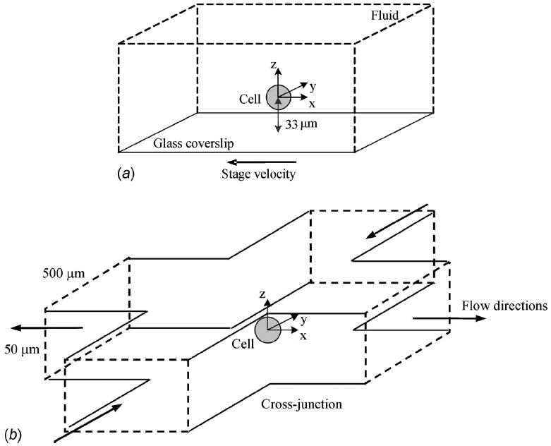
Experimental stresses were recently applied to suspended, nonadhered microspheres and biological cells (radius, a=~10 μm) [10,11]. The original stress analysis was applied to three separate flow conditions: (1) a uniform flow field generated by moving the fluid sample with a translation stage (500 μm/ s freestream), (2) a gravity driven flow through a straight microchannel (460 μm/ s freestream), and (3) a gravity driven flow through a microchannel cross-junction (750 μm/s freestream and a shear rate of γ̇=12.4 strain/ s). These experimental environments created normal and shear stresses with peak values of ~70 mPa. However, many cell monolayer flow studies are capable of applying shear stresses in the range of 1.0 Pa due to faster flow rates of 14 mm/s [13]. In an exploration of the potential for microfluidic applications of stresses at higher levels as well as the induced cellular strain response, two of the flow conditions were each modeled with 0.1, 1.0, and 10.0 Pa peak stresses: (1) a uniform flow field and (2) an extensional flow scenario (Fig. 1).
Fig. 1.

Schematics of the microchannel arrangements creating (a) uniform and (b) extensional flow states [10]
Normal (σr) and shear (τrθ) stress components were derived from the constitutive equation for an incompressible, Newtonian fluid with viscosity (μ) such that
| (1) |
| (2) |
Velocity gradients (here in polar coordinates associated with ur and uθ) were determined directly from experimental flow field measurements using particle image velocimetry. In addition, analytical theory was developed to characterize the two-dimensional flow field velocities at the central perimeter (r and θ in the x-y plane at z=0). Freestream (U∞) and characteristic (U=γ̇a) flow velocities modulated the applied stresses.
2.2 Uniform Flow Stresses
The continuity or momentum equation for axisymmetric, incompressible flow was reduced to the partial differential equation describing the stream function and solved for the velocity components of the Stokes solution for creeping motion past a sphere
| (3) |
| (4) |
Equations (3) and (4) can then be used to calculate the theoretical normal and shear stresses defined by Eqs. (1) and (2) at the cellular surface [14]
| (5) |
| (6) |
Both of these stress states contribute a net drag force component (form drag plus friction drag) applied to a suspended cell in the direction of uniform flow
| (7) |
2.3 Extensional Flow Stresses
For a nonrotating sphere suspended in a general linear, two-dimensional extensional flow microenvironment as created in the described microchannel cross-junction, the velocity components were solved as
| (8) |
| (9) |
Equations (8) and (9) can then be applied to the constitutive Eqs. (1) and (2) resulting in the normal and shear stresses at the mid-plane of the sphere in planar extensional flow at the cellular surface [10]
| (10) |
| (11) |
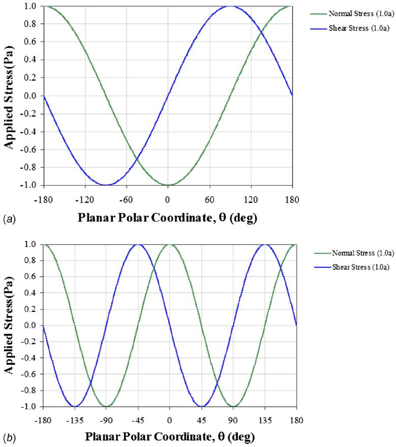
Overall, the resulting hydrodynamic surface stresses for both flow conditions exhibit sinusoidal patterns identifying local spatial dependencies (Fig. 2).
Fig. 2.

Modeled stress patterns applied to suspended cells in microfluidic environments of (a) uniform and (b) extensional flows with peak stresses similar to monolayer studies (~1 Pa). Previous experimental creeping laminar flows in these environments created stress patterns with peak values approximately two orders of magnitude lower (~70 mPa). The planar polar coordinates (r=1.0 a and θ) are defined in the x-y plane at z=0.
2.4 Computational Multiphysics Analysis
In this two-dimensional, multiphysics analysis (comsol v3.5a, COMSOL, Inc., Palo Alto, CA), a range in magnitude of locally applied stresses were included as boundary conditions (100 mPa to 10.0 Pa) for a central cell section (872 nm thick slice at z=0) modeled with a spectrum of mechanical properties representing healthy and diseased states (elastic moduli of E=0.1 to 5.0 kPa and Poisson ratio of ν =0.4). With this modeling approach, dominant hydrostatic stresses were separated from the more spatially sensitive hydrodynamic stresses. Separated strain responses to normal and shear stresses were also characterized regarding their individual contributions via superposition. An initial investigation into homogeneous, isotropic, and elastic cellular properties was explored.
2.5 Modeled Cellular Strains
Multiaxial stress versus strain analyses also included the calculation of strain energy density (SED) by integrating the local multiaxial stress state over the resulting strains to achieve the relationship (shown here in Cartesian coordinates) [15]
| (12) |
incorporating linear elastic moduli (E and G=E/2(1+ν)) and the Poisson ratio (ν). This relationship was further integrated over the volume of the cellular section (20 μm diameter × 872 nm thickness) as associated with twice the experimental planar (z-direction) resolution [16].
3 Results
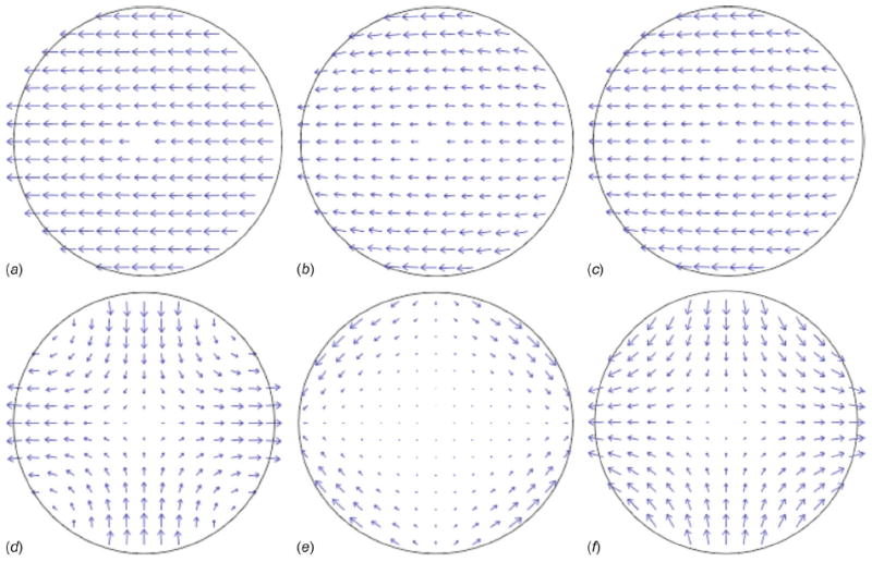
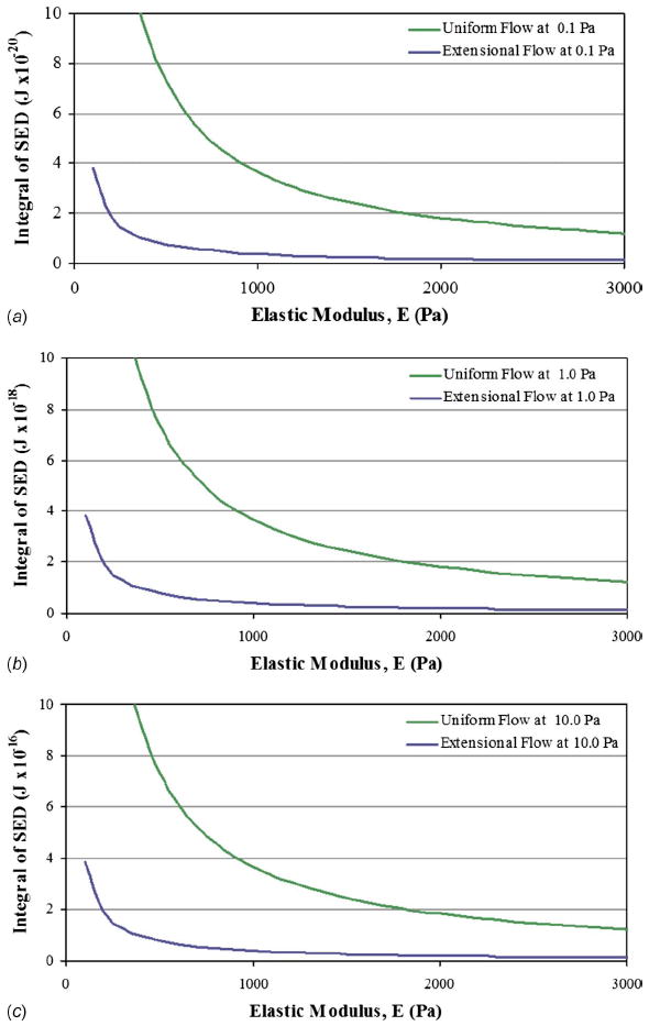
Site-specific strain patterns were characterized within the modeled single cells at a deformation resolution of ~100 nm (Fig. 3). Volumetric cellular strain energy density was calculated to characterize the influence of varying elastic modulus as a metric for disease assay (Fig. 4) where orders of magnitude lower moduli have been indicated for diseased cells in comparison with healthy cells [1]. In order to achieve peak stress values of 1.0 Pa, dramatically faster flow rates would be needed experimentally. Here, a freestream velocity of U∞=7325 μm/ s would be required within the uniform flow environment. This flow rate would also require a 1.49 nN optical trapping force to withstand the applied drag force (FD), a level far beyond the typical 10 to 100 pN trap forces created during low energy trapping required for live cellular manipulation [11]. Within the extensional flow state, a characteristic flow velocity of U=2077 μm/ s would be required for 1.0 Pa peak stresses producing a shear rate of γ̇=202 strain/ s. The cross-junction arrangement can create a mechanically stable environment with a total drag equal to zero if an object is positioned at the geometric center. An undisturbed flow has been created experimentally applying up to 250 mPa and 50 strain/s [11]. This potential stability can be further proven by integrating the stress tensor, defined by the normal (form drag) and shear (friction drag) stress components, about the cell’s perimeter.
Fig. 3.

Strain superposition within a modeled cellular section (20 μm diameter with a 0.5 kPa modulus) due to the applied hydrodynamic stresses (1.0 Pa amplitude) potentially available in straight or open (a, b, c sequence) and cross-junction (d, e, f sequence) microfluidic channel configurations. Normal stress-induced strains in tension or compression (a and d) plus shear-induced strains (b and e) equals the total cellular strain state (c and f), where arrow length represents magnitude.
Fig. 4.

The relationship between SED integrated over the cell’s sectioned volume due to a range of cellular elastic moduli. Applied extensional and uniform stress conditions with (a) 0.1 Pa, (b) 1.0 Pa, and (c) 10.0 Pa in amplitude are shown. For each order of magnitude increase in applied stress, the integrated SED increases by two orders of magnitude with similar curve shapes.
4 Discussion
The results of this work have uniquely identified the range of potential mechanical strains produced in multiaxial fluid-induced stress applications. For each order of magnitude increase in applied stress such as calculated for amplitudes 0.1, 1.0, and 10.0 Pa, the integrated SED increases by two orders of magnitude with similar curve shapes. The resulting models provide a glimpse into the potential for faster microfluidic flow rates as well as the response of weaker cells to increased fluid-induced stresses.
The mechanical sensitivity of cellular structures with low elastic moduli associated with disease (<0.5 kPa) may indicate their receptivity to increased damage thus exacerbating the disease itself. Previous studies have indicated possible cellular stiffening as a reaction to applied loads as well as a cellular softening during stiff matrix accumulation [17,18]. However, loading beyond the cell’s capacity or an excessive deformational response (>35%) may limit the cell’s reparative capability leading to degeneration and/or apoptosis [19,20]. Perhaps of greater implication is the recent progress in the study of diseased cell biomechanics generating a greater understanding of the mechanical properties involved in cell morphology, motility, adhesion, and invasion [1].
In terms of biologic adaptation driven by local SED modulation, this concept has long been postulated at the tissue level [21]. Aspects of this theory explain some of the known morphological effects associated with external tissue-loading variations in magnitude and frequency as correlated with mechanisms of cellular mechanosensing and signaling [22]. Cells such as osteocytes are mechanically coupled to the bone matrix such that increasing the load frequency improves the responsiveness of the tissue to loading, especially in regions of high strain energy [23]. Stretch-activated ion channels and focal adhesion proteins may play a role in the adaptive triggering response.
This work modeled the mechanical strain response to normal and shear hydrodynamic stresses applied locally to suspended cell structures in microfluidic environments. The hydrodynamic stress state was increased to match current monolayer studies while ignoring the inevitably large hydrostatic pressures (as in orders of magnitude), which may be needed to drive faster flow rates. In the previous experimental analysis [10], these pressures ranged from −1.469 Pa (uniform flow field) to −146.9 Pa (straight microchannel flow) to −239.5 Pa (microchannel cross-junction flow). Simple microfluidic channel designs relying on soft lithography and polydimethylsiloxane (PDMS) fabrication may not be able to retain fluids during higher pressure flow states, although advance techniques have demonstrated fluidic containment up to 100 kPa [24]. Another possibility or minimizing fluid pressure while maintaining the pressure differential and maximizing fluid velocity gradient (and thus the applied stresses) is to lower the fluid “head height” on the downstream flow channel rather than raising it on the upstream side, effectively “pulling” the fluid through the microchannel rather than “pushing” it. Overall, the described environment provides the opportunity to assess cell biomechanics with or without cellular adhesion responses.
Ongoing modeling efforts incorporate detailed three-dimensional cytoskeletal geometries, which distinctly identify intracellular structures (membrane, fibers, organelles, etc.) to produce more realistic stress-strain relationships associated with isolated cell biomechanics studies [25]. This information will help to identify experimental stress states necessary to illicit a mechanical strain and in-turn hypothetical biologic responses, leading to novel mechanotransduction relationships.
Acknowledgments
Support was provided by an Academic Research Enhancement Award (Grant No. EB007077) and an Exploratory Program grant (Grant No. MD003350) both from the National Institutes of Health, the Collins Medical Trust, and Portland State University Faculty Enhancement and Travel Grants.
Footnotes
Paper presented in part at the ASME 2010 First Global Congress on Nanoengineering for Medicine and Biology: Advancing Health Care Through Nanoengineering and Computing, Houston, TX, Feb. 7–10, 2010.
Contributor Information
Zachary D. Wilson, Reparative Bioengineering Laboratory, Department of Mechanical and Materials Engineering, Portland State University, Portland, OR 97207
Sean S. Kohles, Reparative Bioengineering Laboratory, Department of Mechanical and Materials Engineering, Portland State University, Portland, OR 97207; Department of Surgery, Oregon Health & Science University, Portland, OR 97239, kohles@cecs.pdx.edu
References
- 1.Cross SE, Jin YS, Rao J, Gimzewski JK. Nanomechanical Analysis of Cells From Cancer Patients. Nat Nanotechnol. 2007;2:780–783. doi: 10.1038/nnano.2007.388. [DOI] [PubMed] [Google Scholar]
- 2.Kamm RD, Kaazempur-Mofrad MR. On the Molecular Basis for Mechanotransduction. Mech Chem Biosyst. 2004;1(3):201–209. [PubMed] [Google Scholar]
- 3.Hunter P, Nielsen P. A Strategy for Integrative Computational Physiology. Physiology (Bethesda, MD) 2005;20:316–325. doi: 10.1152/physiol.00022.2005. [DOI] [PubMed] [Google Scholar]
- 4.Kim W, Tretheway DC, Kohles SS. An Inverse Method for Predicting Tissue-Level Mechanics From Cellular Mechanical Input. J Biomech. 2009;42(3):395–399. doi: 10.1016/j.jbiomech.2008.11.014. [DOI] [PMC free article] [PubMed] [Google Scholar]
- 5.Lim CT, Zhou EH, Quek ST. Mechanical Models for Living Cells-A Review. J Biomech. 2006;39(2):195–216. doi: 10.1016/j.jbiomech.2004.12.008. [DOI] [PubMed] [Google Scholar]
- 6.Walker LM, Holm A, Cooling L, Maxwell L, Oberg A, Sundqvist T, El Haj AJ. Mechanical Manipulation of Bone and Cartilage Cells With Optical Tweezers. FEBS Lett. 1999;459:39–42. doi: 10.1016/s0014-5793(99)01169-2. [DOI] [PubMed] [Google Scholar]
- 7.Guck J, Ananthakrishnan R, Mahmood H, Moon TJ, Cunningham CC, Kas J. The Optical Stretcher: A Novel Laser Tool to Micromanipulate Cells. Biophys J. 2001;81:767–784. doi: 10.1016/S0006-3495(01)75740-2. [DOI] [PMC free article] [PubMed] [Google Scholar]
- 8.Bao G, Suresh S. Cell and Molecular Mechanics of Biological Materials. Nature Mater. 2003;2(11):715–725. doi: 10.1038/nmat1001. [DOI] [PubMed] [Google Scholar]
- 9.Nève N, Lingwood JK, Zimmerman J, Kohles SS, Tretheway DC. The μPIVOT: An Integrated Particle Image Velocimeter and Optical Tweezers Instrument for Microenvironment Investigations. Meas Sci Technol. 2008;19(9):095403. doi: 10.1088/0957-0233/19/9/095403. [DOI] [PMC free article] [PubMed] [Google Scholar]
- 10.Kohles SS, Nève N, Zimmerman JD, Tretheway DC. Stress Analysis of Microfluidic Environments Designed for Isolated Biological Cell Investigations. ASME J Biomech Eng. 2009;131(12):121006. doi: 10.1115/1.4000121. [DOI] [PMC free article] [PubMed] [Google Scholar]
- 11.Nève N, Kohles SS, Winn SR, Tretheway DC. Manipulation of Suspended Single Cells by Microfluidics and Optical Tweezers. Cell Mol Bioeng. 2010;3(3):213–228. doi: 10.1007/s12195-010-0113-3. [DOI] [PMC free article] [PubMed] [Google Scholar]
- 12.Poole CA, Flint MH, Beaumont BW. Chondrons in Cartilage: Ultrastructural Analysis of the Pericellular Microenvironment in Adult Human Articular Cartilages. J Orthop Res. 1987;5(4):509–522. doi: 10.1002/jor.1100050406. [DOI] [PubMed] [Google Scholar]
- 13.Su SS, Schmid-Schönbein GW. Fluid Stresses on the Membrane of Migrating Leukocytes. Ann Biomed Eng. 2008;36(2):298–307. doi: 10.1007/s10439-007-9406-7. [DOI] [PMC free article] [PubMed] [Google Scholar]
- 14.Bird RB, Stewart WE, Lightfoot EN. Transport Phenomena. Wiley; NY: 1960. [Google Scholar]
- 15.Cook RD, Young WC. Advanced Mechanics of Materials. Macmillan; NY: 1985. [Google Scholar]
- 16.Hinojosa C, Zimmerman J, Nève N, Tretheway D. 3-D Velocity Measurements Around an Optically Suspended Sphere. 62nd Annual Meeting, APS Division of Fluid Dynamics; Minneapolis, MN. 2009. Paper No MN.00008. [Google Scholar]
- 17.Kohles SS, Wilson CG, Bonassar LJ. A Mechanical Composite Spheres Analysis of Engineered Cartilage Dynamics. ASME J Biomech Eng. 2007;129(4):473–480. doi: 10.1115/1.2746366. [DOI] [PMC free article] [PubMed] [Google Scholar]
- 18.Preiss-Bloom O, Mizrahi J, Elisseeff J, Seliktar D. Real-Time Monitoring of Force Response Measured in Mechanically Stimulated Tissue-Engineered Cartilage. Artif Organs. 2009;33(4):318–327. doi: 10.1111/j.1525-1594.2009.00723.x. [DOI] [PubMed] [Google Scholar]
- 19.Shieh AC, Athanasiou KA. Biomechanics of Single Chondrocytes and Osteoarthritis. Crit Rev Biomed Eng. 2002;30(4–6):307–343. doi: 10.1615/critrevbiomedeng.v30.i456.40. [DOI] [PubMed] [Google Scholar]
- 20.Ofek G, Natoli RM, Athanasiou KA. In Situ Mechanical Properties of the Chondrocyte Cytoplasm and Nucleus. J Biomech. 2009;42(7):873–877. doi: 10.1016/j.jbiomech.2009.01.024. [DOI] [PMC free article] [PubMed] [Google Scholar]
- 21.Vanderby R, Jr, Manley PA, Belloli DM, Kohles SS, Thielke RJ, McBeath AA. Femoral Strain Adaptation After Total Hip Replacement. Proc Inst Mech Eng Part H: J Eng Med. 1990;204:97–109. doi: 10.1243/PIME_PROC_1990_204_238_02. [DOI] [PubMed] [Google Scholar]
- 22.Ruimerman R, Van Rietbergen B, Hilbers P, Huiskes R. The Effects of Trabecular-Bone Loading Variables on the Surface Signaling Potential for Bone Remodeling and Adaptation. Ann Biomed Eng. 2005;33(1):71–78. doi: 10.1007/s10439-005-8964-9. [DOI] [PubMed] [Google Scholar]
- 23.Turner CH, Warden SJ, Bellido T, Plotkin LI, Kumar N, Jasiuk I, Danzig J, Robling AG. Mechanobiology of the Skeleton. Sci Signal. 2009;2(68):pt. 3. doi: 10.1126/scisignal.268pt3. [DOI] [PMC free article] [PubMed] [Google Scholar]
- 24.Cooksey GA, Plant AL, Atencia J. A Vacuum Manifold for Rapid World-to-Chip Connectivity of Complex PDMS Microdevices. Lab Chip. 2009;9(9):1298–1300. doi: 10.1039/b820683j. [DOI] [PubMed] [Google Scholar]
- 25.Wilson ZD, Kohles SS. Volumetric Stress Analysis of Hydrodynamically Suspended Biological Cells. ASME J Biomech Eng. doi: 10.1115/1.4002939. in press. [DOI] [PMC free article] [PubMed] [Google Scholar]


