Abstract
Cell migration in a cultured neuronal network presents an obstacle to selectively measuring the activity of the same neuron over a long period of time. Here we report the use of nanopillar arrays to pin the position of neurons in a noninvasive manner. Vertical nanopillars protruding from the surface serve as geometrically better focal adhesion points for cell attachment than a flat surface. The cell body mobility is significantly reduced from 57.8 µm on flat surface to 3.9 µm on nanopillars over five day period. Yet, neurons growing on nanopillar arrays show a growth pattern that does not differ in any significant way from that seen on a flat substrate. Notably, while the cell bodies of neurons are efficiently anchored by the nanopillars, the axons and dendrites are free to grow and elongate into the surrounding area to develop a neuronal network, which opens up opportunities for long-term study of the same neurons in connected networks.
Keywords: Nanopillar, neuron, cell growth, cell migration, extracellular recording
A fundamental understanding of neural network formation, transmission and remodeling requires measurements of individual neuron activities including firing threshold, firing rate and temporal sequence1. Extracellular approaches such as patterned multi-electrode arrays (MEA)2–4 and planar field effect transistors4 have been successful in simultaneously measuring multi-cell activities over an extended period of time and thus have provided valuable information regarding the development and formation of neuronal networks. For example, the emergence of synchronous electrical firing pattern and developmental changes of the network activity have been observed in networks of cultured cortical neurons5–7. In such studies, dissociated neurons obtained from fetal or neonatal brains are cultured atop the embedded electrodes or transistors. Electric signals generated by a neuron can be detected extracellularly if there is an electrode in close contact. However, it has been difficult to consistently measure the activity of the same neuron over a long term period. This difficulty is partly due to neuron mobility and partly due to lack of neuron-to-electrode specificity8. Neurons cultured on a flat substrate tend to migrate over time, especially in the first few weeks9, 10. The migration range can be as long as hundreds of micrometers and well beyond the detection range of a single electrode or transistor. As a result, patterned electrodes or transistors are not always monitoring the activity of the same neuron as neurons move around. This presents a challenge to monitoring individual neuron activities in a neuronal network for an extended time (up to months), which demands stable and specific neuron-electrode correspondence.
Considerable efforts have been put forth to control the migration of neurons and thus to improve the neuron-electrode interface11–16. The first approach is to promote neuron-to-electrode attachment by (1) chemical modification of the micro-electrode surface via self-assembled monolayers of cell attractive or repulsive molecules11, 16 or (2) patterned deposition of adhesion-promoting proteins as by micro-contact printing12–15. This approach makes micro patterns of adhesive molecules that promote neuron growth on the patterned electrodes. However, the current techniques do not perform consistently when the patterned features reach single cell scale. Each electrode rarely has just a single neuron growing atop; they generally have either no neurons or a cluster of neurons attached. In addition, axons and dendrites are also constrained to the patterned area, which limits free development of neural networks. The second approach involves fabricating neurocages/wells and picket fences that physically trap neuron cell bodies to stay in contact with the same electrodes8, 17–19. Neuroncages developed in the Pine group were able to achieve one-to-one neuron-to-electrode correspondence and thus measure the activity of the same neuron over several weeks8. Picket fences developed in Fromhrez group were able to immobilize snail neurons on a silicon chip19. However, the fabrication of physical traps such as these requires complicated procedures and the process of loading one neuron per neurocage/trap can be tricky and time-consuming. The key features in those neurocages and fences are in the scale of multiple micrometers.
While previous techniques try to prevent neuron migration by chemically or physically confining them, we seek to engineer unique nanostructures that foster, rather than imposing, residence of neuron cell bodies atop the electrode of interest. In the last few years, a number of studies at the interface of nanotechnology and cell biology show that vertically aligned nanowires support cell attachment and survival20–27. Vertical nanowires were also shown to deliver large molecules such as proteins and DNAs into the attached cell21, 22. Those studies indicate intimate and nondestructive interactions between vertical nanowires and biological cells. In this work, we explore the use of vertical nanopillars to reduce cell mobility on the substrate while maintaining normal function and activity of neurons. We find that vertical nanopillars serve as geometrically superior focal adhesion points for cell attachment and reduce the migration of neurons that are in contact with them. Individual neurons are pinned when by chance they are plated on the nanopillars or migrate to be in contact with them, and thus special cell-loading processes are not necessary. In addition, the small size of the nanopillar and the tendency of the cell membrane to wrap around the nanopillar indicates that each nanopillar, if serving as an electrode, would detect signals only from a single neuron. Therefore, nanopillars have the potential of recording the same neuron over an extended period of time.
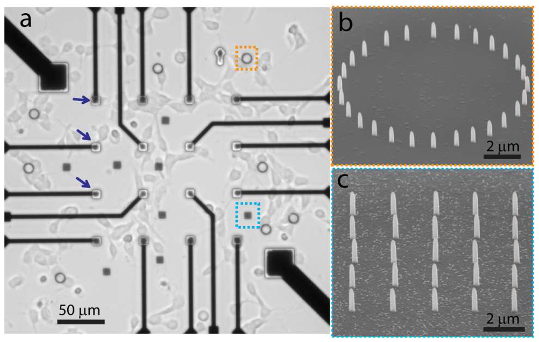
Vertical nanopillars are fabricated by ion-beam or e-beam induced platinum deposition using a dual-beam focused ion beam (FIB) / scanning electron microscope (SEM) system. Platinum material is chosen for its biocompatibility and potential to directly measure the electrical activities of attached neurons. The dimensions of the nanopillars are typically 150 nm in diameter and 1 µm in height. The locations of the nanopillars can be precisely controlled. Nanopillar patterns are normally fabricated on top of the electrodes of a customized MEA substrate in order to anchor neurons at the electrode locations (Fig. 1a). Non-transparent MEA electrodes make it difficult to observe nanopillars or neurons on top of them using optical microscopy. Thus, we also fabricate nanopillars in the transparent area of the fused quartz substrate to demonstrate the cell pinning effect of the nanopillars (enclosed by the blue and orange squares in Fig 1a). Two types of nanopillar patterns are tested – a ring-shaped circle with 10 µm diameter (Fig. 1b) and a 5×5 square array with 2 µm spacing (Fig. 1c).
Figure 1.
Illustration of cultured neurons on a nanopillar substrate. (a) A bright field image of neurons cultured on a MEA substrate with nanopillar arrays located both on the microelectrodes (blue arrows) and in open areas (orange and cyan squares). (b) SEM image of a ring-shaped nanopillar array. (c) SEM image of a 5×5 square nanopillar array.
Embryonic cortical neurons are isolated from E18 rats according to previously published protocols28. The nanopillar substrate is cleaned by oxygen plasma, sterilized in 70% ethanol and coated with 1mg/ml poly-L-lysine before cell plating. Dissociated neurons are plated on the nanopillar substrate and maintained in neurobasal medium supplemented with B27 and L-glutamine. Optical microscope images are taken every day to track the growth and migration of neurons on or off the nanopillars. Neurons that have cell bodies or neurites attached to the nanopillars display survival rate and cell morphology similar to those that are not in proximity to the nanopillars.
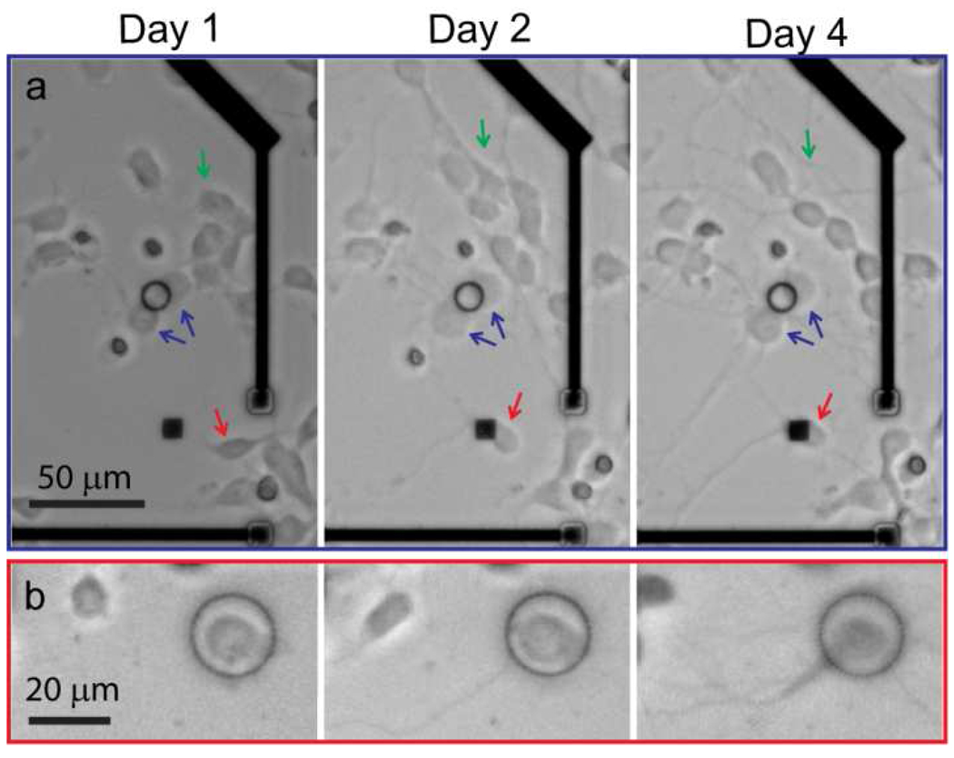
Figure 2 displays representative images that show distinct cell mobility for those neurons that are in close contact with the nanopillar arrays and those that are not. Neurons that are not attached to the nanopillars are mobile, and some migrate distances over a hundred micrometers in 4 days (green arrow in Fig. 2a). In contrast, neurons in contact with the nanopillar patterns exhibit significantly hindered movement. For example, two neuron cell bodies attached to a nanopillar ring (as indicated by the blue arrow in Fig. 2a) are essentially stationary over the four day period, despite extending out long axons. The red arrow points to a neuron that migrates freely on the first day before reaching a nanopillar square array on the second day. Over the next two days, the neuron significantly elongates its neurites but its cell body stays at the same location. In Fig. 2b, a neuron plated inside a nanopillar ring at the very beginning stays inside the ring for the whole period.
Figure 2.
Migrations of cortical neurons are followed at 1 day, 2 days and 4 days after plating. Over this 4-day period, neurons that are in contact with nanopillar arrays display significantly reduced mobility compared with those that are not. On the other hand, all neurons show similar morphology, survival rate and neurite elongation rate. (a) Neurons that are not in contact with nanopillars (green arrows) are significantly more mobile over 4 days than those neurons in close contact with nanopillars (blue arrows). The red arrow points to a neuron that is very mobile in the first day on the flat surface before it comes into contact with a square nanopillar array and is arrested there. (b) A neuron initially plated inside a nanopillar ring is trapped inside.
Typical migration traces of four neurons on the flat substrate and four neurons attached to the nanopillar arrays are plotted in Fig. 3a in a polar graph. From the center outward, these data points represent center locations of cell bodies from day 1 to day 5, relative to the location of their locations on day 1. It is obvious that the migration of neurons is effectively inhibited by nanopillars. While neurons on flat substrate migrate on-average 60µm distances in five days, nanopillar-pinned neurons are mostly confined within 5 µm range. Even this movement occurs mostly on the first day after pinning, during which the neurons move to increase their attachment to the nanopillars. Afterward, the pinned neurons move very little. In Fig. 3b, statistics of neuron migration distances are summarized. The cell movement is calculated as the sum of each neuron’s movement every day. After five days of observation, free-migrating neurons counted over 42 cells show a mean movement of 57.8 µm, while nanopillar-pinned neurons counted over 21 cells only have a mean movement of 3.9 µm.
Figure 3.
Statistics of cell migration over 5 days. (a) Typical movement traces of 4 nanopillar-pinned and 4 free-migrating neurons. Bottom right plot shows zoom-in of the nanopillar-pinned cell movements. While the free-migrating neurons explore ~60µm distances, the nanopillar-pinned cells move no more than 5µm. (b) Analysis of neuron movements over 42 free-moving and 21 nanopillar-pinned neurons show that nanopillars effectively stopped the migration of neurons.
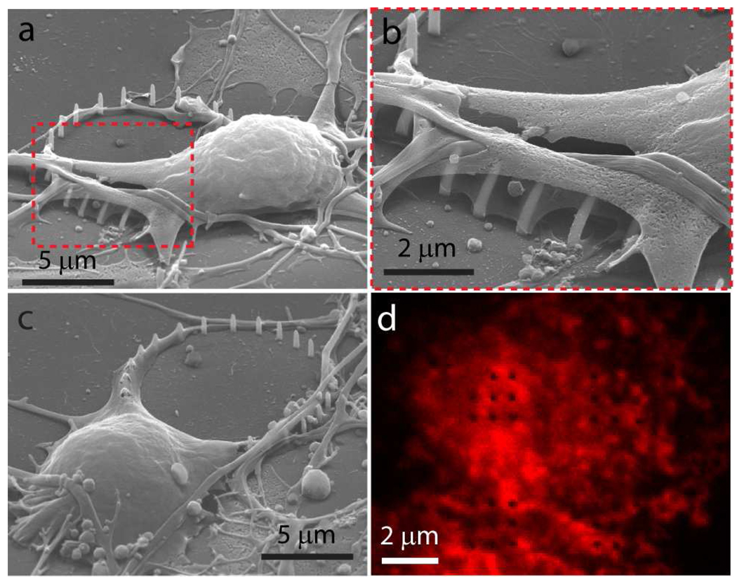
In order to closely examine the nanopillar-neuron interface, neurons cultured on the nanopillar substrate are fixed and imaged by SEM (Fig. 4a–c). Five days after plating, cells are first fixed by glutaraldehyde treatment and then stained with osmium tetroxide staining for contrast enhancement. The sample is de-hydrated via CO2 critical point drying in order to preserve cell morphology. The shape of the neurons suggests that they not only survive on top of the nanopillars but also preferentially grow attached to the nanopillars (Fig. 4a–c). Fig. 4c illustrates the morphology of a neuron growing just outside a ring of nanopillars. The neuron and its projections show a relative preference to attach and grow on nanopillars versus the flat substrates. The fact that cells usually shift to increase their attachment to the nanopillars once they reach them also implies the same preference. Similar behavior has been observed in some previous research24, 27.
Figure 4.
Examining the neuron-nanopillar interface by SEM and fluorescence microscopy. (a). An SEM image of a neuron growing atop a ring of nanopillars show close-contact between neurons and nanopillars. (b). Zoomed-in picture of (a) shows that cell membrane tightly wrapped around nanopillars. The interaction between the nanopillars and the neurons seem to exert forces on the nanopillars so as to bend some of them. (c). An SEM image of a neuron with one of its neurites preferentially growing along the ring-shaped nanopillar arrays.(d). Confocal microscope image of immunostained actin filaments shows that nanopillars (black dots) are imbedded in the cytoskeletal network.
Nanopillars are usually tightly engulfed by neurons. Even neuritic protrudings try to increase their contact with nanopillars by wrapping them with a thin sheet of membrane (Fig 3b). Some of the nanopillars embedded in the cell are bend, possibly due to a force generated by the cell attachment. The bending is not caused by SEM sample preparation process because it is likewise noted by optical microscope with live cells. It is conceivable that the engulfment of the nanopillars is aided by cytoskeletal elements such as actin filaments and microtubules, which generate mechanical tension around the nanopillars and bend them. To further evaluate the interaction between the nanopillars and the cytoskeleton, neurons are fixed and actin filaments are labeled red with TRITC-conjugated phalloidin. Nanopillar arrays show as black dots both in the confocal fluorescence images (Fig. 4d). The focal plane of the confocal fluorescence image was set at the middle of the nanopillars with z-slice about 0.5 µm. The confocal image confirms that the nanopillars are embedded into the actin cytoskeleton network.
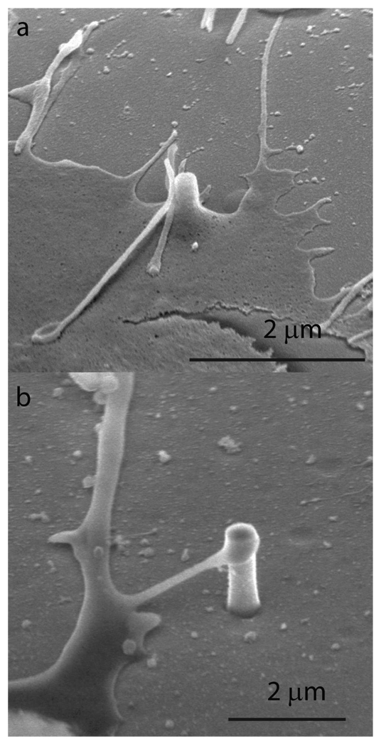
Next, we investigate whether the cell pinning effect is due to the geometry of nanopillars or due to the surface properties of the platinum material. To test this, we fabricate nanopillars with similar geometry but using Si or SiO2 instead of Pt. Si and SiO2 nanopillar structures are fabricated by reactive ion etching using Au or SiO2 nanoparticles as masks. The fabrication process and the subsequent removal of particle masks are carried out as previously described22. The attachment and growth of cortical neurons on the Si and SiO2 nanopillar substrates are similar to those on the Pt nanopillar substrate. SEM analysis (Fig. 5) of neurons growing on Si and SiO2 nanopillar substrates also shows strong interactions between the cell and the nanopillar. Notably, neurite protrudings, which are usually involved in guiding axon elongation and neuron migration, often show a strong tendency to fix their ends on nanopillars, as illustrated in Fig. 5b. This behavior may explain why neurons preferentially migrate towards nanopillars. The fact that similar behavior is observed for nanopillars of all three materials indicates that the pinning effect of nanopillars is likely a geometry effect, rather than a material effect. A conceivable mechanism is that nanopillars protruding from the surface can serve as focal adhesion points. They constitute stronger anchor points for the cell matrix than those formed on a flat surface.
Figure 5.
SEM of cells cultured on Si and SiO2 nanopillar substrates. (a). An SEM image shows a SiO2 pillar engulfed by the cell membrane. (b). An SEM image shows a protruding of a neuron reaching a Si nanopillar.
In summary, we report the use of nanopillar arrays to inhibit the migration of attached neurons. Neurons in close contact with the nanopillars show significantly reduced mobility and are essentially pinned to the nanopillars. Despite this pinning effect, neurons growing on nanopillars show similar growth patterns to those seen on a flat substrate. Within the parameter regime that we have tested (75–400nm in diameter and 700nm-2µm in height), cell survival rate and the pinning effect do not seem to depend on the size of the pillars. If patterned on top of microelectrodes, vertical nanopillars would serve as neuron traps for long-term neuronal network study with MEA and also improve the neuron-to-electrode contact.
Acknowledgements
This work was supported by Bio-X Interdisciplinary Initiatives Program, National Institute of Health (NIH) grant NS057906, Dreyfus new faculty award, Searle Scholar Award and Packard Fellowship to BC.
References
- 1.Windhorst U, Johansson H. Modern techniques in neuroscience research. New York: Springer: Berlin; 1999. 1325 pp. p xxv. [Google Scholar]
- 2.Gross GW. IEEE Trans Biomed Eng. 1979;26(5):273–279. doi: 10.1109/tbme.1979.326402. [DOI] [PubMed] [Google Scholar]
- 3.Pine J. Journal of Neuroscience Methods. 1980;2(1):19–31. doi: 10.1016/0165-0270(80)90042-4. [DOI] [PubMed] [Google Scholar]
- 4.Fromherz P. Chemphyschem. 2002;3(3):276–284. doi: 10.1002/1439-7641(20020315)3:3<276::AID-CPHC276>3.0.CO;2-A. [DOI] [PubMed] [Google Scholar]
- 5.Canepari M, Bove M, Maeda E, Cappello M, Kawana A. Biol Cybern. 1997;77(2):153–162. doi: 10.1007/s004220050376. [DOI] [PubMed] [Google Scholar]
- 6.Jimbo Y, Torimitsu K, Kulagina IB, Korogod SM. European Journal of Neuroscience. 2000;12:383–383. [Google Scholar]
- 7.Kamioka H, Maeda E, Jimbo Y, Robinson HP, Kawana A. Neurosci Lett. 1996;206(2–3):109–112. doi: 10.1016/s0304-3940(96)12448-4. [DOI] [PubMed] [Google Scholar]
- 8.Erickson J, Tooker A, Tai YC, Pine J. Journal of Neuroscience Methods. 2008;175(1):1–16. doi: 10.1016/j.jneumeth.2008.07.023. [DOI] [PMC free article] [PubMed] [Google Scholar]
- 9.Schaar BT, McConnell SK. Proc Natl Acad Sci U S A. 2005;102(38):13652–13657. doi: 10.1073/pnas.0506008102. [DOI] [PMC free article] [PubMed] [Google Scholar]
- 10.Nichols AJ, Carney LH, Olson EC. BMC Neurosci. 2008;9:50. doi: 10.1186/1471-2202-9-50. [DOI] [PMC free article] [PubMed] [Google Scholar]
- 11.Slaughter GE, Bieberich E, Wnek GE, Wynne KJ, Guiseppi-Elie A. Langmuir. 2004;20(17):7189–7200. doi: 10.1021/la049192s. [DOI] [PubMed] [Google Scholar]
- 12.Wheeler BC, Corey JM, Brewer GJ, Branch DW. J Biomech Eng. 1999;121(1):73–78. doi: 10.1115/1.2798045. [DOI] [PubMed] [Google Scholar]
- 13.Wyart C, Ybert C, Bourdieu L, Herr C, Prinz C, Chatenay D. Journal of Neuroscience Methods. 2002;117(2):123–131. doi: 10.1016/s0165-0270(02)00077-8. [DOI] [PubMed] [Google Scholar]
- 14.Jun SB, Hynd MR, Dowell-Mesfin N, Smith KL, Turner JN, Shain W, Kim SJ. J Neurosci Methods. 2007;160(2):317–326. doi: 10.1016/j.jneumeth.2006.09.009. [DOI] [PMC free article] [PubMed] [Google Scholar]
- 15.Jungblut M, Knoll W, Thielemann C, Pottek M. Biomed Microdevices. 2009;11(6):1269–1278. doi: 10.1007/s10544-009-9346-0. [DOI] [PMC free article] [PubMed] [Google Scholar]
- 16.Rutten WL, Ruardij TG, Marani E, Roelofsen BH. Acta Neurochir Suppl. 2007;97(Pt 2):547–554. doi: 10.1007/978-3-211-33081-4_63. [DOI] [PubMed] [Google Scholar]
- 17.Maher MP, Pine J, Wright J, Tai YC. Journal of Neuroscience Methods. 1999;87(1):45–56. doi: 10.1016/s0165-0270(98)00156-3. [DOI] [PubMed] [Google Scholar]
- 18.Tooker A, Meng E, Erickson J, Tai YC, Pine J. Conf Proc IEEE Eng Med Biol Soc; 2004. pp. 2542–2545. [DOI] [PubMed] [Google Scholar]
- 19.Zeck G, Fromherz P. Proc Natl Acad Sci U S A. 2001;98(18):10457–10462. doi: 10.1073/pnas.181348698. [DOI] [PMC free article] [PubMed] [Google Scholar]
- 20.Patolsky F, Timko BP, Yu GH, Fang Y, Greytak AB, Zheng GF, Lieber CM. Science. 2006;313(5790):1100–1104. doi: 10.1126/science.1128640. [DOI] [PubMed] [Google Scholar]
- 21.Kim W, Ng JK, Kunitake ME, Conklin BR, Yang PD. Journal of the American Chemical Society. 2007;129(23):7228–7229. doi: 10.1021/ja071456k. [DOI] [PubMed] [Google Scholar]
- 22.Shalek AK, Robinson JT, Karp ES, Lee JS, Ahn DR, Yoon MH, Sutton A, Jorgolli M, Gertner RS, Gujral TS, MacBeath G, Yang EG, Park H. Proceedings of the National Academy of Sciences of the United States of America. 2010;107(5):1870–1875. doi: 10.1073/pnas.0909350107. [DOI] [PMC free article] [PubMed] [Google Scholar]
- 23.Cohen-Karni T, Qing Q, Li Q, Fang Y, Lieber CM. Nano Letters. 2010;10(3):1098–1102. doi: 10.1021/nl1002608. [DOI] [PMC free article] [PubMed] [Google Scholar]
- 24.Hallstrom W, Martensson T, Prinz C, Gustavsson P, Montelius L, Samuelson L, Kanje M. Nano Letters. 2007;7(10):2960–2965. doi: 10.1021/nl070728e. [DOI] [PubMed] [Google Scholar]
- 25.Jiang K, Fan D, Belabassi Y, Akkaraju G, Montchamp JL, Coffer JL. ACS Applied Materials & Interfaces. 2009;1(2):266–269. doi: 10.1021/am800219r. [DOI] [PMC free article] [PubMed] [Google Scholar]
- 26.Qi SJ, Yi CQ, Ji SL, Fong CC, Yang MS. ACS Applied Materials & Interfaces. 2009;1(1):30–34. doi: 10.1021/am800027d. [DOI] [PubMed] [Google Scholar]
- 27.Turner AMP, Dowell N, Turner SWP, Kam L, Isaacson M, Turner JN, Craighead HG, Shain W. Journal of Biomedical Materials Research. 2000;51(3):430–441. doi: 10.1002/1097-4636(20000905)51:3<430::aid-jbm18>3.0.co;2-c. [DOI] [PubMed] [Google Scholar]
- 28.Cui B, Wu C, Chen L, Ramirez A, Bearer EL, Li WP, Mobley WC, Chu S. Proc Natl Acad Sci U S A. 2007;104(34):13666–13671. doi: 10.1073/pnas.0706192104. [DOI] [PMC free article] [PubMed] [Google Scholar]


