Abstract
Controlling the contents of liposomes and vesicles is essential for their use in medicine, biotechnology, and basic research. Cargos such as proteins, DNA, and RNA are of growing interest for therapeutic applications as well as for fundamental studies of cellular organization and function, but controlled encapsulation and mixing of biomolecules within vesicles has been a challenge. Recently, micro fluidic encapsulation has been shown to efficiently load arbitrary solutions of biomolecules into unilamellar vesicles. This method utilizes a piezo-electrically driven liquid jet to deform a planar bilayer and form a vesicle, with the fluid vortex formed by the jet mixing the solution in the jet with the surrounding solution. Here, we describe the equipment and protocol used for loading mixtures within unilamellar vesicles by microfluidic encapsulation, and we measure the encapsulated fraction to be 79 ± 5% using a falling vesicle technique. Additionally, we find that the presence of a continuous flow from the nozzle and changes in actuation voltage polarity do not significantly affect the encapsulated fraction. These results help to guide current applications and future development of this microfluidic encapsulation technique for forming and loading unilamellar vesicles.
1. INTRODUCTION
Successful clinical applications of lipid-encapsulated drugs over the past two decades have fueled interest in developing liposomes containing a mixture of biomolecular components that are capable of multiple therapeutic and diagnostic functions. Current applications of liposomes, which are typically 50–200 nm in diameter, include drug delivery (Düzgüneş et al., 1995, 2005; Konduri et al., 2005; Salem et al., 2005; Weissig et al., 2006) and diagnostic imaging (Lasic and Papahadjopoulos, 1995; Martina et al., 2005), as well as cosmetics (Ramon et al., 2005). The lipid bilayer membrane boundary of liposomes keeps their contents concentrated and shielded from exposure as they pass through the body. Additionally, modifications of the membrane can be made to improve drug bioavailability and reduce side effects in some clinical applications. When encapsulated in polyethylene glycol-coated liposomes, the anticancer drug Doxorubicin, has been shown to achieve much better performance in tumor targeting (Gabizon et al., 1994) and reduced cardio toxicity (Safra et al., 2000) compared to the unencapsulated form. Additional modification of the vesicle’s bilayer with antibodies, aptamers, or ligands allows encapsulated drugs to be targeted for delivery to sites within the body (Debbage, 2009; Dos Santos et al., 2007; Gantert et al., 2009). Further functionality can be achieved by adding probes that facilitate medical imaging. Liposomes labeled with radionuclides can be imaged using single-photon emission computed tomography and magnetic resonance imaging (Zielhuis et al., 2006), and radiolabeled liposomes containing anticancer therapeutics offer the ability to actively evaluate liposomal drug delivery (Elbayoumi et al., 2007). The opportunity to combine multiple capabilities to address specific clinical needs makes liposomes attractive therapeutic and diagnostic vehicles. Despite the promise of multifunctional liposomes, encapsulating proteins, DNA and RNA, and other high-molecular-weight molecules and inorganic particles within lipid bilayer membrane compartments has been a challenge.
Over decades of liposome research, many methods have been developed to produce synthetic vesicles. One simple method to form vesicles is to dry a lipid film from organic solvent onto the bottom of a flask and rehydrate the film over the course of hours with an aqueous solution. Slight agitation is used to aid in the budding process (Reeves and Dowben, 1969). The resulting vesicles are multilamellar and vary in size. Based on the process, this technique is often referred to as swelling or hydration. Extrusion is a technique used to produce unilamellar vesicles of controlled size, which, involves taking a population of multilamellar vesicles and passing them repeatedly through a filter (Olson et al., 1979). As the filter pore size is decreased, the vesicle population approaches that of the pore size. Below a pore diameter of 0.2 µm, extruded vesicles are uniform in size distribution. With the electroformation technique, lipids are dried onto a surface and immersed in a buffer solution. An alternating electric field is applied across the lipid film to produce a population of giant unilamellar vesicles with a heterogeneous size distribution (Angelova and Dimitrov, 1986). The electroinjection technique uses electroporation to facilitate the insertion of a small diameter tip into a liposome followed by the injection of the desired contents (Karlsson et al., 2000). Although this method is impressive in its capability to control the vesicle contents, it is highly limited in throughput. In reverse-phase evaporation, aqueous solution is added to a suspension of lipid in an organic solvent. The solution is sonicated and the solvent is evaporated, leaving large unilamellar vesicles (Szoka and Papahadjopoulos, 1978). Some of these techniques can be combined to produce a desired population of vesicles, although combining techniques compounds the limitations of each method. For example, any vesicle formation process which uses extrusion to form vesicles of a uniform size distribution will be limited to sizes below that produced by a 0.2-µm pore. The ideal vesicle formation technique would offer uniform size distributions comparable to extruded vesicles, unilamellarity comparable to electroformed vesicles, and precise control over contents comparable to electro injection without the respective limitations.
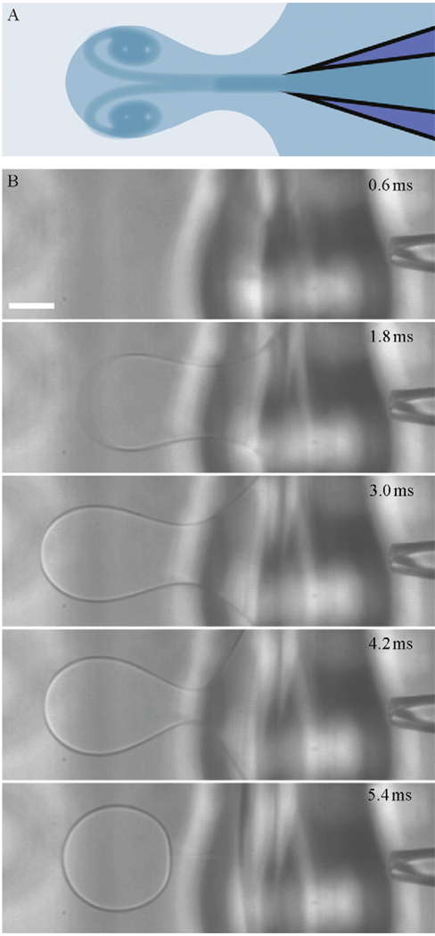
In 2008, we demonstrated that a liquid jet generated by a piezoelectrically actuated plunger–syringe system can be used to deform a planar lipid bilayer to make unilamellar vesicles loaded with contents of unrestricted size (Stachowiak et al., 2008). More recently, we demonstrated that high-throughput vesicle formation and control of vesicle size (10–400 µm) can be achieved with an inkjet system (Stachowiak et al., 2009). Figure 4.1 shows images of the formation process taken from a high-speed video. This technique is unique in that it offers the ability to form unilamellar vesicles with a high encapsulation efficiency and homogeneous size distribution at a high throughput rate (up to 200 Hz). Additionally, the fluid jet that forms the vesicle entrains the surrounding fluid in the process, which allows the user to simultaneously mix two fluids inside the vesicle during formation in order to trigger reactions or vary solution concentrations within the vesicle. Vesicles on the scale of micrometers to tens of micrometers can be used directly for cell-like reconstitution, in which the spatial organization and reaction dynamics of cellular structures such as those formed by the cytoskeleton can be studied. To obtain liposomes on the scale of 100 nm, the vesicles can be sonicated or extruded as noted earlier, with contents expected to be similar to those of the original vesicle (Sugiura et al., 2008). We have previously demonstrated the unilamellarity of the vesicles formed with our technique by inserting membrane pores and confirming the existence of membrane tubes during vesicle formation (Stachowiak et al., 2008).
Figure 4.1.
Inkjet-based microfluidic encapsulation to form unilamellar vesicles. (A) Diagram of the fluid jet and vortex ring deforming a planar lipid bilayer. (B) High-speed image sequence of the vesicle formation process. Conditions used to form vesicles are 20 pulses of a 35 V trapezoidal signal. A 200 mOsm sucrose solution is used in the inkjet and surrounding droplet to make a vesicle of 100% sucrose which is formed into a solution of 200 mOsm glucose. Scale bar represents 100 µm.
As microfluidic encapsulation matures as a technique for vesicle and liposome formation, there is a need to understand the efficiency at which two solutions—one in the jet and one surrounding the jet—can be encapsulated within a vesicle. Control over encapsulation efficiency allows one to accurately initiate a chemical reaction between the two solutions within the vesicle at the time of formation. Additionally, control over fluid mixing offers real-time management of the encapsulation fraction, allowing for convenient variation in concentration during an experiment, which is important for biological reconstitutions and small volume reactions. In this chapter, we investigate the vesicle encapsulation fraction, defined as the fraction of vesicle volume originating from the fluid surrounding the jet, using the falling drop method applied to vesicles. Our results on quantifying and controlling the encapsulated fraction are important for improving the reliability and usefulness of the micro fluidic encapsulation technique.
2. UNILAMELLAR VESICLE FORMATION BY MICROFLUIDIC ENCAPSULATION
In this section we describe the equipment and protocol used for generating vesicles by microfluidic encapsulation.
2.1. Inkjet vortex ring generator
Our microfluidic encapsulation technique for unilamellar vesicle formation is based on the ability to precisely form and control a liquid jet. We have chosen a single inkjet drop-on-demand device as a means of generating the liquid jet and tuning vortex dynamics. This inkjet device consists of a glass capillary surrounded by a cylindrical piezoelectric sleeve. Excitation of the piezoelectric actuator, by application of a voltage pulse, forces the piezo-electric sleeve to contract and expand around the glass capillary causing acoustic compression and rarefaction waves to propagate laterally along the nozzle. In typical inkjet usage, the excitation signal is tuned such that constructive and destructive interference among the waves leads to a compression wave with large enough amplitude to overcome the surface tension at the orifice and cause the ejection of a fluid droplet from the inkjet nozzle (Bogy and Talke, 1984). In our implementation, the inkjet is submerged in a miscible fluid such that there is no surface tension at the orifice, and therefore fluid ejection may be achieved by a smaller compression amplitude and is less dependent on optimizing the interference of waves. The bulk of the inkjet device used in our experiment is manufactured and assembled by Microfab Technologies, while the nozzle of the inkjet is manufactured in-house with an orifice diameter of ~10 µm using a P-97 Flaming/Brown micropipette puller (Sutter Instruments) and an MFG-3 Microforge (MicroData Instrument).
Through software controls, one can design the voltage profile used to excite the piezoelectric actuator. In many drop-on-demand applications, the voltage profile consists of a positive amplitude, or upright, trapezoidal profile followed by a negative amplitude, or inverted, trapezoidal profile. We have found that using a full upright and inverted trapezoidal profile provided power beyond what is needed to form vesicles, and thus we limited the voltage profile to an upright trapezoidal shape for simplicity. Adequate ejection of fluid to form a vesicle generally requires the application of numerous pulses of the trapezoidal waveform (Stachowiak et al., 2009). Parameters for vesicle formation vary depending on the distance between the inkjet tip and bilayer, the viscosity of the solutions, and the condition of the lipid in the bilayer. Typical parameters for the experiments reported in this manuscript are a trapezoidal voltage profile with a 3-µs rise time from 0 to 35 V, a dwell time of 30 µs, and a fall time of 3 µs from 35 to 0 V, repeated for 20 pulses at a frequency of 20 kHz.
2.2. Microscopy of vesicle formation
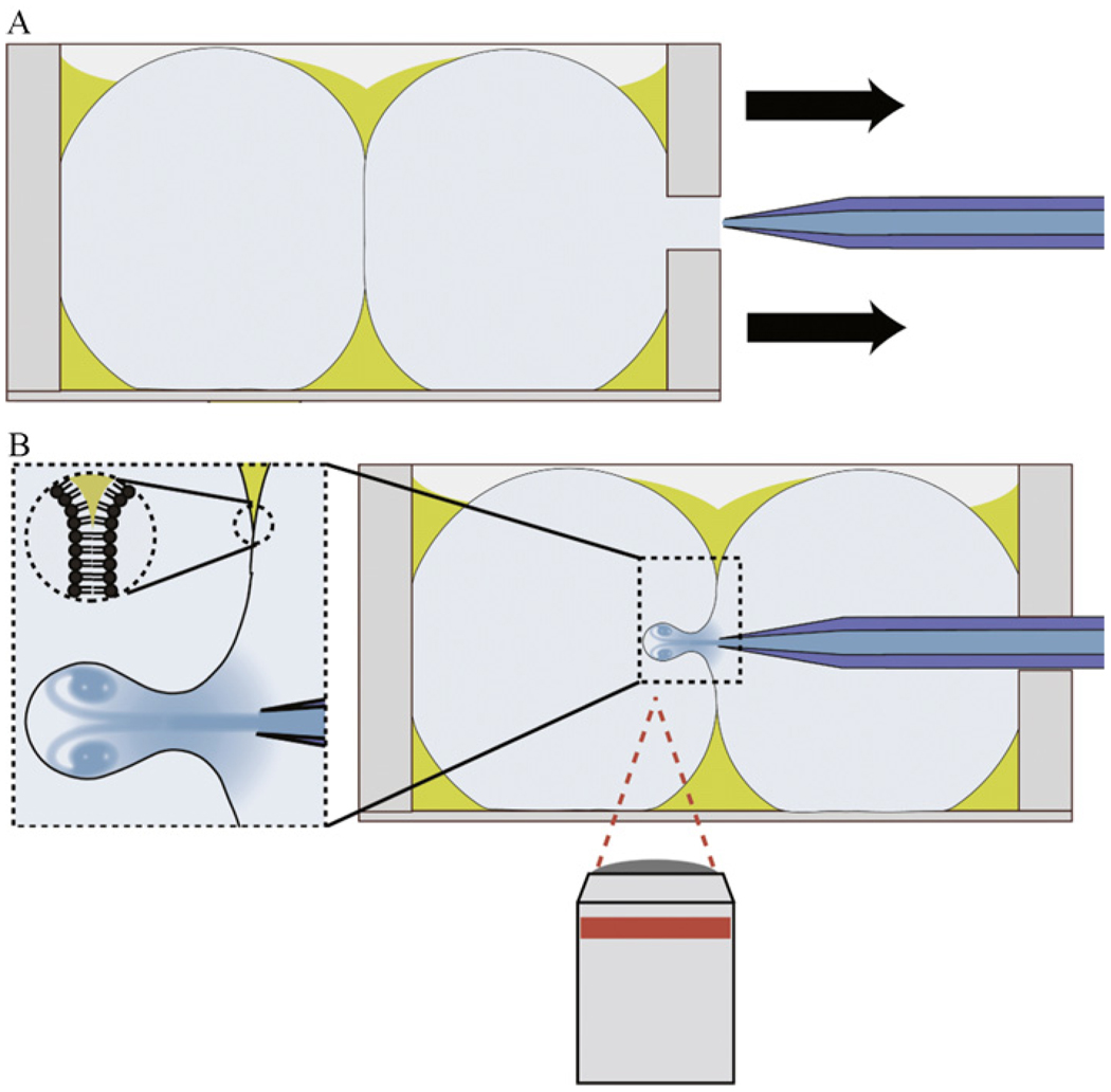
Our microfluidic encapsulation system is built on an Axiovert 200 microscope base (Carl Zeiss), which was modified to facilitate vesicle production. The original microscope stage was replaced by a custom stage made to accommodate the jetting device. The stage is composed of parts purchased from Thorlabs or machined in house. The custom stage uses two sets of three axis translation stages. The first set of translation stages is used to position the entire system (inkjet device, formation chamber, and fixtures) relative to the microscope base for viewing, while the second set of stages is used to insert and position the inkjet device relative to the vesicle formation chamber as shown in Figure 4.2.
Figure 4.2.
Illustration of the experimental setup used for making vesicles by microfluidic encapsulation. (A) A lipid bilayer is formed between two aqueous droplets in a chamber independent from the inkjet. (B) Inkjet nozzle is inserted into the chamber holding the bilayer and steered within range of the bilayer to form unilamellar vesicles by moving the chamber. This alignment procedure occurs on a microscope where the formation process can be recorded. Fluid flows continuously from the inkjet orifice to maintain the solution concentration inside the nozzle.
A high-speed camera is used to visualize the vesicle formation process. In our experiments, we use a monochrome Photron 1024PCI high-speed camera controlled through Photron Fastcam Viewer software. For typical vesicle formation processes, the full 1024×1024 pixel CCD area is usually reduced to a region-of-interest of approximately 600×200 pixels to facilitate high frame rate recording. The camera is triggered from a TTL signal generated at the instant that the inkjet device is triggered. For most situations, a frame rate of approximately 5000 fps is used, which yields roughly 25 frames during the formation process. Generally, a 5× objective is used, which yields a field-of-view of 2 mm×0.6 mm when limiting the region-of-interest to 600×200 pixels.
In addition to the high-speed camera, a low-magnification side-view camera (Micropublisher 3.3 RTV, Qimaging) controlled through QCapture software has been added to the microscope. While the high-speed camera images from the underside of the system to record an image plane parallel to the table surface, the side-view camera is mounted to image the system on a plane perpendicular to the plane of the table surface. The main use of the side-view camera is to align the inkjet system and the vesicle chamber along the vertical direction. The side-view camera uses a 4× objective (Edmund Optics) and images a 4 cm × 3 cm field-of-view. A 45° mirror along the imaging path further reduces the field-of-view to 3 cm × 3 cm.
2.3. Nozzle flow system
In addition to the high-speed jet formed by the piezoelectric actuator, a continuous slow nozzle flow is used to prevent diffusion of outside fluid into the nozzle of the inkjet. Positive pressure inside the nozzle helps to minimize clogs in the nozzle due to particles in the solution surrounding the inkjet. If the solution inside the inkjet is different than the surrounding solution, the flow can be used to manipulate the solution concentration around the tip orifice. To enable continuous nozzle flow, the rear of the inkjet is attached by a Luer-Lock fitting to a 1-ml disposable syringe (Becton Dickinson). A motorized CMA-12PP linear actuator (Newport) connected to the plunger of the syringe, allows the user to drive fluid from the syringe through the inkjet and out the front of the nozzle prior to inkjet actuation and vesicle formation. The CMA-12PP actuator used for this setup is controlled through SMC100 software. During typical usage the actuator is run at a rate of 0.0003 mm/s which corresponds to a volumetric flow rate of 0.019 ml/h when used with a 1-ml BD syringe. The flow velocity out of the inkjet nozzle due to this flow system is calculated to be ~66 mm/s.
3. DETERMINATION OF ENCAPSULATION FRACTION WITHIN VESICLES
In this section, we describe a method for determining the encapsulation fraction within vesicles formed by micro fluidic encapsulation when different solutions are used in and around the jet.
3.1. Falling vesicle method
To initiate chemical reactions and reconstitute biological machinery within the vesicles, it is important to know and control the ratio of two solutions mixed within the vesicle. The density of a droplet has been determined previously by the falling drop method (Sims, 1954) and, more recently, this method has been used to calculate the volume of oil present in double emulsions formed by jets (Funakoshi et al., 2007). We use the falling drop method with vesicles to determine vesicle density due to the entrainment and mixing of two solutions during vesicle formation. The density of the solution within the vesicle is a linear combination of the solution jetted by the inkjet and the surrounding solution that is entrained into the jet vortex before the vesicle is formed. By jetting one solution of known density (sucrose) through a second solution (glucose) of known density, the fraction of each fluid within the vesicle can be determined.
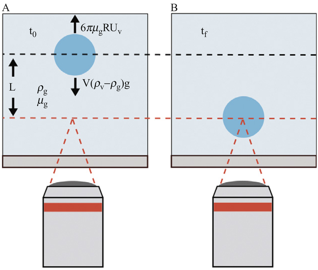
To measure the fall time of the vesicle the plane of focus of the microscope objective is set to the plane of the inkjet and then lowered a recorded distance downward such that vesicles would be formed out of focus and fall a determined distance into focus, as illustrated in Figure 4.3. The fall distance is established by focusing on the mid plane of the inkjet tip then lowering the objective a distance of 0.5 mm calibrated in air. The fall distance is then corrected using Snell’s law to account for the refractive index of the glucose and sucrose solutions. Using the high-speed camera with a time stamp on each frame, the fall time of the vesicle can be determined. Acceleration time is assumed to be negligibly small (~0.01 s) and the terminal velocity of the vesicle is determined from the recorded distance and fall time. By excluding data with Reynolds number greater than 0.1, we limit the flow regime to fully laminar where Stokes law has been shown to be highly accurate (Rhodes, 1998). The vesicles are assumed to remain perfectly spherical during the falling process. This assumption is evaluated by calculating the Bond number (Bo), the ratio of body forces to surface tension, as shown in the following equation:
| (4.1) |
Figure 4.3.
Illustration of experimental setup of the falling vesicle method used to estimate the encapsulation fraction of vesicles. (A) Focus of the microscope objective is offset a given distance prior to vesicle formation. (B) The fall time of the vesicle is used to estimate the density of vesicles. Glucose and sucrose solutions of known density and viscosities are used, and the fraction of each solution encapsulated in the vesicle is determined.
In our experiments, a vesicle filled completely with sucrose yields a Bond number of ~0.0004, which fulfills the requirement of being significantly smaller than unity. Therefore, the spherical approximation is valid and the velocity of the vesicle can be described by the Stokes equation, shown in the following equation:
| (4.2) |
where Δρ is the difference in density between the surrounding and internal fluid. The density of the surrounding fluid can be measured beforehand, leaving only the density of the fluid within the vesicle to be solved. In our case, the fluid surrounding the vesicle and the fluid entrained by the jet vortex are both 200 mOsm glucose. The resulting encapsulation fraction of glucose in the vesicle is given by
| (4.3) |
where Eg is the fraction of glucose encapsulated within the vesicle.
3.2. Entrainment by vortex rings
The entrainment process occurs before the pinch off of the vesicle, during the formation of the vortex ring. Studies on single vortex ring entrainment have been performed by Gharib et al. (1998), who used a piston-cylinder vortex generator to determine the limiting stroke-to-diameter ratio, beyond which a vortex ring would pinch off from the trailing jet. This limiting ratio of approximately 4 was termed the formation number. Beyond this number the translational vortex velocity exceeds that of the trailing jet and fluid from the jet is no longer delivered to the vortex ring (Shusser and Gharib, 2000). Later, Dabiri and Gharib (2004) demonstrated that a vortex ring’s entrainment fraction of surrounding fluid increased monotonically until the formation number was reached and pinch off occurred. The bulk of the entrainment occurs during this time and entrainment values of 30–40% were measured at and beyond pinch off. Additionally, Dabiri and Gharib were able to increase the entrainment fraction to 65% by delaying vortex pinch off beyond the formation time through the use of bulk counter flow.
In contrast to the piston-cylinder generator used in single vortex studies, our inkjet system produces a series of vortex rings traveling along the same axis (Stachowiak et al., 2009). In the case of multiple vortex rings, Stachowiak et al. observed that the rearward rings in the trailing jet catch up to the lead vortex ring and combine to form a single, large composite vortex ring, a phenomenon that has been documented before with two vortex rings (Maxworthy, 1972). An effective stroke length for the first vortex generated by our inkjet can be estimated by multiplying the exit velocity by the period of a single voltage pulse. Using our high-speed camera at 30,000 frames/s, the exit velocity was estimated to be approximately 1.1m/s, and duration of each voltage pulse was 50 µs based on a pulse frequency of 20 kHz. With an orifice diameter of ~10 µm, we found the stroke-to-diameter ratio of the first vortex ring to be ~5.5, which exceeds the formation number. Using this estimation one would expect that the first vortex ring produced by our system would contain 30–40% of the surrounding fluid if no subsequent rings were formed. Catching up of the rearward rings to the first vortex ring may be analogous to delaying the pinch off of the lead vortex ring in that fluid from the trailing jet continues to be delivered to the first vortex ring beyond the formation time. In this way, the entrainment fraction of the final composite vortex ring would have an expected value greater than 30–40% of surrounding fluid. Since this vortex ring goes on to deform the lipid bilayer until it collapses into a vesicle encapsulating the vortex, one would expect the entrapment fraction of the vesicle to be correlated to the entrainment fraction of the composite vortex ring. We carried out the experiments described below to test this entrainment prediction for vesicles formed by microfluidic encapsulation.
3.3. Solution preparation
DPHPC (1,2-diphytanoyl-sn-glycero-3-phosphocholine) lipid suspended in decane (C10H22) is used to form the planar bilayer. The lipid (Avanti Polar Lipids) comes dissolved in chloroform (CHCl3) and sealed under argon atmosphere. In preparation for usage, a 25-mg vial of lipid is opened and divided into two glass test tubes, and the bulk of the chloroform is evaporated off under a gentle stream of nitrogen gas for approximately 20 min. The two test tubes are then placed into a vacuum chamber for 1 h to finalize chloroform removal. After drying, 0.5 ml of filtered decane (0.22 µm pore) is added to each test tube to produce a final concentration of 25 mg/ml of DPHPC suspended in decane.
A sucrose solution is used as the solution in the inkjet. A 200-mOsm sucrose solution is initially prepared by dissolving 3.42 g of crystalline sucrose (Fisher Scientific) into filtered deionized water for a final volume of 50 ml. The concentration is checked with an Osmette II osmometer (Precision Instruments). Before each experiment the sucrose solution is refilltered through a 0.22-µm pore filter to minimize particulates.
For the following experiments, a glucose solution is used as the medium surrounding the vesicles and as the solution entrained by the jet. A 200-mOsm solution is made by mixing 1.80 g of crystalline glucose with deionized, filtered water to a final volume of 50 ml. The concentration is checked using an osmometer and the solution is also filtered before usage.
3.4. Effect of planar bilayer age on oil exclusion in vesicles
To test the accuracy of the falling drop method for estimating encapsulation fraction, vesicles containing only sucrose solution are formed. This is done by loading the inkjet with a 200-mOsm sucrose solution and surrounding the inkjet in the same solution. Vesicles are made using a trapezoidal voltage profile with a 3 µs linear rise time, 30 µs dwell time at 35 V, and a fall time of 3 µs back to 0 V. Each vesicle is made by applying this voltage profile 20 times at a frequency of 20 kHz to create 20 pulses that coalesce into a single vortex ring. The vesicles are formed into a less dense 200 mOsm glucose solution and begin sinking immediately. The fall time of the vesicle is then recorded and used to determine whether the falling drop method could accurately give the expected settling rate for a sucrose-filled vesicle, equivalent to an encapsulation fraction of glucose of exactly zero.
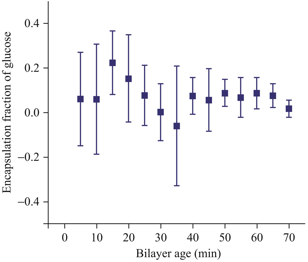
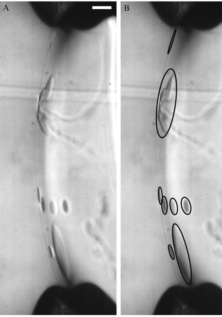
Estimating the encapsulation fraction using vesicles formed within 30 min of forming the planar lipid bilayer led to large variability in the results. Figure 4.4 shows the variability in estimated glucose encapsulation fraction decreases ~30 min after the bilayer formation. Before the 30 min mark, the mean fraction of glucose entrapped was estimated to be 0.11 with a standard deviation of 0.19. Vesicles formed after the 30 min mark had a mean and standard deviation of 0.05 and 0.12, respectively. The most likely explanation for the time dependence is the presence of oil lenses during the formation and growth of the bilayer in the first 30 min. Using second harmonic generation microscopy, Ries et al. observed a similar time scale for the incorporation, growth, and exclusion of solvent in black lipid membranes, noting a growth dependence on the substrate used to support the black lipid membranes (Ries et al., 2004). Figure 4.5 shows oil lenses suspended in the bilayer. The presence of decane in the bilayer can result in oil within the vesicle membrane that obscures encapsulation estimations early in the bilayer lifetime.
Figure 4.4.
Experimental demonstration of the falling vesicle method with 0% glucose (100% sucrose) vesicles. The accuracy of the falling vesicle method was tested by measuring the falling rate of sucrose-filled vesicles in glucose and confirming that the calculated encapsulation fraction of glucose was zero. Early variability in the data suggests the presence of oil lenses in vesicles interfering with falling drop estimations for times <30 min.
Figure 4.5.
Image of oil lenses suspended in the lipid bilayer shortly after formation. The presence of oil lenses supports the observation of variability in the falling vesicle data at early times and suggests experiments should wait ~30 min after the bilayer is formed before making vesicles to ensure oil is excluded from the bilayer. Oil lenses in the image on the left are circled in the image on the right. Scale bar represents 100 um.
3.5. Effect of continuous flow on encapsulation fraction
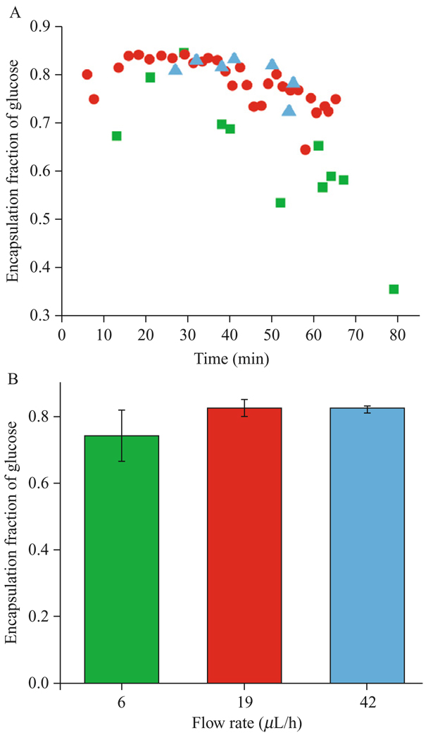
To test the effect of vortex entrainment on encapsulation fraction, 200 mOsm glucose solution is used to surround the inkjet and 200 mOsm sucrose solution is loaded inside the inkjet. The vesicles are formed into 200 mOsm glucose solution on the opposite side of the lipid bilayer. Vesicles are formed using the same voltage parameters described in Section 3.4. The nozzle flow system is used to slowly flow 200 mOsm sucrose solution through the inkjet. The purpose of the flow in this situation is to alter the local concentration of fluid surrounding the inkjet from pure glucose to a mix of glucose and sucrose. One might expect that the higher flow rate would lead to a higher local concentration of sucrose surrounding the inkjet tip and result in a lower encapsulation fraction of glucose. We experimentally measured encapsulation fraction of glucose at three flow rates, 0.006, 0.019, and 0.042 ml/h, as shown in Figure 4.6.
Figure 4.6.
Experimentally determined glucose encapsulation fraction by the falling vesicle method comparing three different nozzle flow rates, with (A) encapsulation fraction over time and (B) average encapsulation fraction for each flow rate during the first 40min. Vesicles are formed by jetting sucrose solution through glucose. The lack of a trend suggests that continuous flow through the nozzle does not significantly affect encapsulation fraction in vesicles.
The lowest flow rate of 0.006 ml/h resulted in vesicles with a mean glucose encapsulation fraction of 0.64 and standard deviation of 0.13. Vesicles formed in the presence of 0.019 ml/h flow had a mean glucose encapsulation fraction of 0.79 with a standard deviation of 0.05. The highest flow rate resulted in vesicles with a mean glucose encapsulation fraction of 0.80 and a standard deviation of 0.04. At 95% confidence level, the set of vesicles made with a 0.019-ml/h flow rate were not statistically different from the vesicles made using a 0.042 ml/h flow rate. The lower encapsulation fraction of glucose in vesicles formed using the 0.006 ml/h flow suggests that other factors may be influencing encapsulation fraction, such as the separation distance between the bilayer and inkjet tip. At higher flow rates the fluid volume added around the inkjet is large enough to bend the bilayer away from the inkjet tip, requiring the inkjet to be repositioned to maintain an approximately constant separation distance. Agitating the fluid surrounding the inkjet tip would lower local concentration of sucrose, leading to high glucose encapsulation corresponding to higher flow.
3.6. Effect of inverting voltage polarity on encapsulation fraction
One explanation for the observed low encapsulation of fluid from the jet (sucrose) compared to fluid from surrounding the jet (glucose) is that no net flow from within the inkjet nozzle is actually expelled during the generation of the liquid jet that deforms the bilayer membrane during vesicle formation. This is possible because the inkjet generates the jet acoustically rather than through slug flow. Since expansion and contraction of the piezoelectric actuator forms acoustic waves in pairs, each compression wave has a corresponding rarefaction wave of equal amplitude. This equal and opposite pairing leads to oscillation of fluid in and out of the inkjet device that delivers momentum to drive the jet but provides no net fluid from within the inkjet nozzle to the jet itself. If this hypothesis is correct, and the jet that forms the vesicle is generated by fluid oscillations rather than slug flow from the inkjet, different voltage signals that produce the same oscillations should yield similar encapsulation fraction. More specifically, a positive voltage profile should lead to vesicles with encapsulation fractions comparable to those created by the equivalent negative, or inverted, voltage profile.
As described earlier, the inkjet is driven by repeat application of a trapezoidal voltage trace which rises from 0 to 35 V. Under these conditions, acoustic waves are generated by repeat expansion of the diameter of the inkjet’s capillary tube. The same inkjet device can generate acoustic waves by contracting the capillary diameter using an inverted trapezoidal voltage signal which falls from 0 to −35 V. All other parameters including the timing and number of pulses applied remained the same for this experiment.
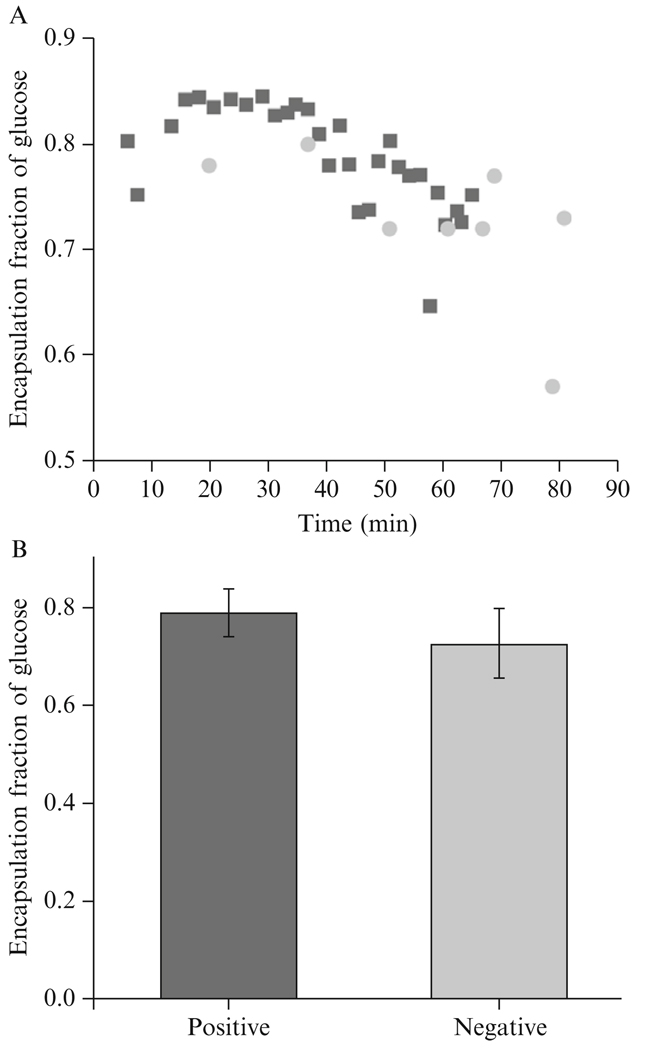
As in the previous experiment, the fluid within the inkjet was 200 mOsm sucrose, while the fluid surrounding the inkjet and the newly formed vesicles was 200 mOsm glucose. The flow rate was set to 0.019 ml/h. Using the inverted voltage trace, the resulting vesicles had a mean glucose encapsulation fraction of 0.73 and a standard deviation of 0.07. At a 95% confidence level, the encapsulation fraction of vesicles produced using the positive trapezoidal trace and vesicles produced using negative voltage trace were not statistically different, as shown in Figure 4.7.
Figure 4.7.
Experimentally determined glucose encapsulation fraction by the falling vesicle method comparing vesicles made by an inkjet driven by a positive voltage trace and a negative voltage trace, with (A) encapsulation fraction over time and (B) average encapsulation fraction for both polarities over the entire time. No statistical difference at 95% confidence level suggests no difference in the encapsulation process for different polarities.
This result provides insight into the inkjet driven vortex formation process. In the case of the positive trapezoidal signal, the increase in voltage leads to a rarefaction wave reaching the tip first. With no surface tension to counteract the wave, a small amount of fluid immediately outside of the orifice will be pulled into the inkjet and subsequently ejected when the voltage decreases back to zero, causing a compression wave to propagate to the orifice. In the case of a negative trapezoidal signal, a compression wave reaches the tip first, ejecting a small volume of liquid immediately inside of the orifice, and the rarefaction wave that follows draws liquid in from immediately outside the orifice. With repeat pulses the oscillations generated by the positive profile should be identical to the oscillations generated by the inverted profile. The findings of this experiment suggest that there are no differences in fluid mixing that occur from driving the inkjet with a positive voltage trace rather than a negative trace, which is likely an effect of the jet being generated acoustically rather than through bulk flow.
3.7. Discussion
The main advantage of estimating the encapsulation fraction using the falling drop method is simplicity. Given the described vesicle formation system, a viscometer, and a scale, the encapsulation fraction of vesicles can be quickly estimated. This method can be done with no modifications to the vesicle formation device, and therefore it can be performed as a precursor to another assay with minimal additional effort. Furthermore, encapsulation fraction can be estimated using a single vesicle which offers convenience over bulk estimation methods (Oku et al., 1982).
Several fundamental assumptions are made in the application of Stokes law that can limit the accuracy of the falling method. The fluid surrounding the vesicle is assumed to be infinite in volume to have no wall effects, based on the experiment using purely sucrose-filled vesicles this approximation seems acceptable for the current chamber design; however, future vesicle chambers may evolve toward a more compact micro fluidic design, in which case the infinite fluid assumption may not be satisfied. Stokes drag applies to a solid sphere while the Rybczynski–Hadmard equation offers a more accurate prediction which accounts for circulation for a falling fluid sphere under the same condition (Lamb, 1932). The drag on a vesicle should fall between the two results as a vesicle should have reduced inner fluid circulation compared to free fluid droplet. Experiments using vesicles filled with only 200 mOsm sucrose suggest that Stokes law as a more appropriate estimation of the drag on a vesicle than the Rybczynski–Hadmard equation. Application of Stokes law requires low Reynolds and Bond numbers, which also limits the solution combinations that can be used in this method; large differences in densities greatly reduce the applicability of Stokes law. In situations where greater accuracy is required, encapsulation estimations can potentially be done using quantitative fluorescence on individual vesicles, though establishing a calibration standard is a challenge.
To generalize the encapsulation results to other experimental situations, one must consider the vortex ring. When a vortex is created, the formation number is a function of the vortex generator parameters rather than the fluid properties. Therefore, one could expect similar rapid entrainment fractions across vortex rings of different fluid properties produced using the same stroke-to-diameter ratios exceeding the formation number. Although the vortex rings may have similar entrainment fractions, the vortex ring energy will vary by fluid density for a Norbury family of vortex rings (Norbury, 1973). Therefore, variation in fluid properties may result in vortex rings that do not possess the energy to adequately deform the lipid bilayer into a vesicle. Beyond the rapid fluid entrainment during formation, vortex rings continue to grow and entrain ambient fluid through slow viscous diffusion which is governed by both time and fluid viscosity. This secondary entrainment process is therefore influenced by both the fluid properties and the vortex generator parameters and must be carefully considered for each experiment.
4. CONCLUDING REMARKS
In this chapter, we have presented details of the micro fluidic encapsulation technique for forming unilamellar vesicles with mixed contents, and we have demonstrated the use of the falling drop method for determining the encapsulated fraction of solutions mixed by vortex entrainment. In doing so, we have documented practical considerations that are important for forming vesicles and controlling encapsulation fraction. We find there is a marked advantage in allowing the bilayer to age prior to formation of vesicles in order to exclude oil; however, no advantage is gained by simply inverting the driving voltage signal of the inkjet. Our measurements of encapsulated fraction of ~80% are significantly larger than estimates from previous vortex ring experiments, suggesting that the presence of the planar bilayer and details of the multiple inkjet pulses are significant for control of entrainment and encapsulation. We have found that ability of continuous nozzle flow to control the encapsulation fraction of two different solutions is limited, suggesting that other strategies must be used for expanding control of mixing. Combining solutions during micro fluidic encapsulation is an important step toward the formation of complex unilamellar vesicles and liposomes, and continued development of the technique will be aimed at improving the ability to measure and control this property.
REFERENCES
- Angelova M, Dimitrov D. Liposome electroformation. Faraday Discuss. 1986;81:303–311. [Google Scholar]
- Bogy DB, Talke FE. Experimental and theoretical-study of wave-propagation phenomena in drop-on-demand ink jet devices. IBM J. Res. Develop. 1984;28:314–321. [Google Scholar]
- Dabiri JO, Gharib M. Fluid entrainment by isolated vortex rings. J. Fluid Mech. 2004;511:311–331. [Google Scholar]
- Debbage P. Targeted drugs and nanomedicine: Present and future. Curr. Pharm. Des. 2009;15:153–172. doi: 10.2174/138161209787002870. [DOI] [PubMed] [Google Scholar]
- Dos Santos N, Allen C, Doppen A-M, Anantha M, Cox KAK, Gallagher RC, Karlsson G, Edwards K, Kenner G, Samuels L, Webb MS, Bally MB. Influence of poly(ethylene glycol) grafting density and polymer length on liposomes: Relating plasma circulation lifetimes to protein binding. Biochim. Biophys. Acta. 2007;1768:1367–1377. doi: 10.1016/j.bbamem.2006.12.013. [DOI] [PubMed] [Google Scholar]
- Düzgüneş N, Flasher D, Pretzer E, Konopka K, Slepushkin VA, Steffan G, Salem II, Reddy MV, Gangadharam PRJ. Liposome-mediated therapy of human immunodeficiency virus type-1 and Mycobacterium infections. J. Liposome Res. 1995;5:669–691. [Google Scholar]
- Düzgüneş N, Simões S, Slepushkin V, Pretzer E, Flasher D, Salem II, Steffan G, Konopka K, Pedroso de Lima MC. Delivery of antiviral agents in liposomes. Methods Enzymol. 2005;391:351–373. doi: 10.1016/S0076-6879(05)91020-3. [DOI] [PubMed] [Google Scholar]
- ElBayoumi TA, Pabba S, Roby A, Torchilin VP. Antinucleosome antibody-modified liposomes and lipid-core micelles for tumor-targeted delivery of therapeutic and diagnostic agents. J. Liposome Res. 2007;17:1–14. doi: 10.1080/08982100601186474. [DOI] [PubMed] [Google Scholar]
- Funakoshi K, Suzuki H, Takeuchi S. Formation of giant lipid vesiclelike compartments from a planar lipid membrane by a pulsed jet flow. J. Am. Chem. Soc. 2007;129:12608–12609. doi: 10.1021/ja074029f. [DOI] [PubMed] [Google Scholar]
- Gabizon A, Catane R, Uziely B, Kaufman B, Safra T, Cohen R, Martin F, Huang A, Barenholz Y. ). Prolonged circulation time and enhanced accumulation in malignant exudates of doxorubicin encapsulated in polyethylene-glycol coated liposomes. Cancer Res. 1994;54(4):987–992. [PubMed] [Google Scholar]
- Gantert M, Lewrick F, Adrian JE, Roessler J, Steenpass T, Schubert R, Peschka-Suess R. Receptor-specific targeting with liposomes in vitro based on sterol-PEG(1300) anchors. Pharm. Res. 2009;26:529–538. doi: 10.1007/s11095-008-9768-z. [DOI] [PubMed] [Google Scholar]
- Gharib M, Rambod E, Shariff K. A universal time scale for vortex ring formation. J. Fluid Mech. 1998;360:121–140. [Google Scholar]
- Karlsson M, Nolkrantz K, Davidson MJ, Stromberg A, Ryttsen F, Akerman B, Orwar O. Electroinjection of colloid particles and biopolymers into single unilamellar liposomes and cells for bioanalytical applications. Anal. Chem. 2000;72:5857–5862. doi: 10.1021/ac0003246. [DOI] [PubMed] [Google Scholar]
- Konduri K, Nandedkar S, Rickaby DA, Düzgünesş N, Gangadharam PRJ. The use of sterically stabilized liposomes to treat asthma. Methods Enzymol. 2005;391:413–427. doi: 10.1016/S0076-6879(05)91023-9. [DOI] [PubMed] [Google Scholar]
- Lamb H. Hydrodynamics. Cambridge: The University Press; 1932. [Google Scholar]
- Lasic DD, Papahadjopoulos D. Liposomes revisited. Science. 1995;267:1275–1276. doi: 10.1126/science.7871422. [DOI] [PubMed] [Google Scholar]
- Martina MS, Fortin JP, Menager C, Clement O, Barratt G, Grabielle-Madelmont C, Gazeau F, Cabuil V, Lesieur S. Generation of super-paramagnetic liposomes revealed as highly efficient MRI contrast agents for in vivo imaging. J. Am. Chem. Soc. 2005;127:10676–10685. doi: 10.1021/ja0516460. [DOI] [PubMed] [Google Scholar]
- Maxworthy T. The structure and stability of vortex rings. J. Fluid Mech. 1972;51:15–32. [Google Scholar]
- Norbury J. A family of steady vortex rings. J. Fluid Mech. 1973;57:417–431. [Google Scholar]
- Oku N, Kendall DA, Macdonald RC. A simple procedure for the determination of the trapped volume of liposomes. Biochim. Biophys. Acta. 1982;691:332–340. [Google Scholar]
- Olson F, Hunt CA, Szoka FC, Vail WJ, Papahadjopoulos D. Preparation of liposomes of defined size distribution by extrusion through polycarbonate membranes. Biochim. Biophys. Acta. 1979;557:9–23. doi: 10.1016/0005-2736(79)90085-3. [DOI] [PubMed] [Google Scholar]
- Ramon E, Alonso C, Coderch L, De la Maza A, Lopez O, Parra JL, Notario I. Liposomes as alternative vehicles for sun filter formulations. Drug Deliv. 2005;12:83–88. doi: 10.1080/10717540490446080. [DOI] [PubMed] [Google Scholar]
- Reeves JP, Dowben RM. Formation and Properties of thin-walled phospholipid vesicles. J. Cell Physiol. 1969;1:49–60. doi: 10.1002/jcp.1040730108. [DOI] [PubMed] [Google Scholar]
- Rhodes M. Introduction to particle technology. New York: Wiley; 1998. [Google Scholar]
- Ries RS, Choi H, Blunck R, Bezanilla F, Heath JR. Black lipid membranes: Visualizing the structure, dynamics, and substrate dependence of membranes. J. Phys. Chem. B. 2004;108:16040–16049. [Google Scholar]
- Safra T, Muggia F, Jeffers S, Tsao-Wei DD, Groshen S, Lyass O, Henderson R, Berry G, Gabizon A. Pegylated liposomal doxorubicin (doxil): Reduced clinical cardiotoxicity in patients reaching or exceeding cumulative doses of 500 mg/m(2) Ann. Oncol. 2000;11:1029–1033. doi: 10.1023/a:1008365716693. [DOI] [PubMed] [Google Scholar]
- Salem II, Flasher DL, Düzgüneş N. Liposome-encapsulated antibiotics. Methods Enzymol. 2005;391:261–291. doi: 10.1016/S0076-6879(05)91015-X. [DOI] [PubMed] [Google Scholar]
- Shusser M, Gharib M. Energy and velocity of a forming vortex ring. Phys. Fluids. 2000;12:618–621. [Google Scholar]
- Sims RPA. Some observations on determining density of fluids by the falling drop method. Can. J. Chem. 1954;32:506–511. [Google Scholar]
- Stachowiak JC, Richmond DL, Li TH, Liu AP, Parekh SH, Fletcher DA. Unilamellar vesicle formation and encapsulation by microfluidic jetting. Proc. Natl. Acad. Sci. USA. 2008;105:4697–4702. doi: 10.1073/pnas.0710875105. [DOI] [PMC free article] [PubMed] [Google Scholar]
- Stachowiak JC, Richmond DL, Li TH, Brochard-Wyart F, Fletcher DA. Cell-like encapsulation by high-throughput inkjet printing of unilamellar lipid vesicles. Lab Chip. 2009 doi: 10.1039/b904984c. doi:10.1039/B904984C. [DOI] [PMC free article] [PubMed] [Google Scholar]
- Sugiura S, Kuroiwa T, Kagota T, Nakajima M, Sato S, Mukataka S, Walde P, Ichikawa S. Novel method for obtaining homogeneous giant vesicles from a monodisperse water-in-oil emulsion prepared with a microfluidic device. Langmuir. 2008;24:4581–4588. doi: 10.1021/la703509r. [DOI] [PubMed] [Google Scholar]
- Szoka F, Jr, Papahadjopoulos D. Procedure for preparation of liposomes with large internal aqueous space and high capture by reverse-phase evaporation. Proc. Natl. Acad. Sci. USA. 1978;75:4194–4198. doi: 10.1073/pnas.75.9.4194. [DOI] [PMC free article] [PubMed] [Google Scholar]
- Weissig V, Boddapati SV, Cheng S-M, D’Souza GGM. Liposomes and liposome-like vesicles for drug and DNA delivery to mitochondria. J. Liposome Res. 2006;16:249–264. doi: 10.1080/08982100600851169. [DOI] [PubMed] [Google Scholar]
- Zielhuis SW, Seppenwoolde JH, Mateus VAP, Bakker CJG, Krijger GC, Storm G, Zonnenberg BA, van het Schip AD, Koning GA, Nijsen JFW. Lanthanide-loaded liposomes for multimodality imaging and therapy. Cancer Biother. Radiopharm. 2006;21:520–527. doi: 10.1089/cbr.2006.21.520. [DOI] [PubMed] [Google Scholar]


