Abstract
Fluorescent Cybesin (Cypate-Bombesin Peptide Analogue Conjugate) was synthesized from Indocyanine Green (ICG) and the bombesin receptor ligand as a contrast agent for detecting pancreas tumors. However, the LC–MS analysis indicated that the target compound was only a minor component in the reaction mixture. Since preparative HPLC can hardly separate such a small amount of the target compound directly from the original crude reaction mixture without a considerable adsorptive loss onto the solid support, high-speed counter-current chromatography (HSCCC) was used for purification since the method uses no solid support and promises high sample recovery. A suitable two-phase solvent system composed of hexane/ethyl acetate/methanol/methyl t.-butyl ether/acetonitrile/water) at a volume ratio of 1:1:1:4:4:7 was selected based on the partition coefficient of Cybesin (K ≈ 0.9) determined by LC–MS. The separation was performed in two steps using the same solvent system with lower aqueous mobile phase. From 400 mg of the crude reaction mixture the first separation yielded 7.7 mg of fractions containing the target compound at 12.8% purity, and in the second run 1 mg of Cybesin was obtained at purity of 94.0% with a sample recovery rate of over 95% based on the LC–MS Analysis.
Keywords: High-speed counter-current chromatography, Spiral tube assembly, Isolation and purification, Cybesin, Cypate-Bombesin Peptide Analogue Conjugate, Pancreas tumor
1. Introduction
Indocyanine Green (ICG), a clinically approved Near-infrared (NIR) dye by FDA, is one of the most widely studied cyanine dyes. As a small ICG-derivative dyepeptide, Cypate-Bombesin Peptide Analogue Conjugate (Cybesin) was used as a contrast agent to detect pancreas tumors. Not only it preferentially localizes for over 24 hours in tumors with over-expressed bombesin receptors in a small animal model [1], but also it is preferentially taken up by human prostate cancer cells compared to the normal prostate cells [2].
This compound is mainly composed of ICG and the bombesin receptor ligand (Fig. 1), which delivers the ICG to the receptor presented in the tumor [1]. However, the preparative isolation of Cybesin is of significant technical challenge especially if it is present at a low-level in the reaction mixture. In the past the isolation of Cybesin had been mostly based on HPLC which required complicated multiple steps resulting in low recoveries of the target compound, especially for the sample of low purity [1,3]. In contrast, preparative isolation and large-scale purification of natural and synthetic products have been performed by high-speed counter-current chromatography (HSCCC), which is a unique liquid-liquid partition chromatography using a liquid stationary phase without solid support. Consequently, the method has various advantages over the conventional HPLC technique such as no irreversible adsorption, low risk of sample denaturation, high sample recovery rate, large sample loading capacity, low cost [4], and removal of a small amount of impurities that could lower the specific activity of target compound. As far as our knowledge is concerned, the separation of Cybesin from the reaction mixture by HSCCC has not been reported.
Fig. 1.
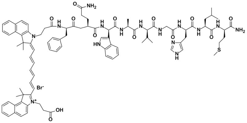
Chemical structure of Cybesin.
This paper describes for the first time successful purification of Cybesin from the crude reaction mixture by HSCCC using a two-phase solvent system composed of hexane, ethyl acetate, methanol, acetonitrile, methyl t.-butyl ether (MBE), and water (1:1:1: 4: 4: 7., v/v), where peak fractions were analyzed by LC–MS to determine the yield and purity of Cybesin.
2. Experimental
2.1. Materials
The crude synthetic reaction mixture containing Cybesin was prepared by Xiaoyuan Chen’s group at the National Institute of Biomedical Imaging and Bioengineering, National Institutes of Health (NIH) in March 2010. The synthesis protocol of this compound was reported elsewhere [1]. All organic solvents used for the preparation of crude sample, HSCCC separation and LC-MS analysis were of chromatographic grade and purchased from Thermo Fisher Scientific Inc. (New Jersey, USA).
2.2. HSCCC separation
2.2.1. Instrumentation
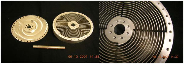
HSCCC separation was performed using a model #1 high-speed counter-current chromatograph (P.C. Inc., Potomac, MD, USA). It holds a spiral tube assembly and a counterweight symmetrically at a distance of 10 cm from the central axis of the apparatus [5]. Spiral tube support was designed in our laboratory and fabricated from an aluminum disk by Mr. Robert Clary at the NIH machine shop (Bethesda, MD, USA). It has 4 interwoven spiral grooves, each 2.8 mm wide and ca 5 cm deep with 4 transfer radial grooves (Fig. 2). The corner of each spiral was rounded to prevent kinking of the tubing. Tefzel tubing of 1.6 mm ID (SW 14) (Zeus Industrial Products, Orangeburg, S.C.) was accommodated tightly into the spiral grooves by squashing with a tool which fits to the radial grooves. After winding, the column was embedded in bee wax to protect tubing from vibration. This spiral tube assembly contained 13 spiral layers with a total capacity of 130 ml.
Fig. 2.
Spiral tube support.
The revolution speed was adjustable, ranging from 0 to 1200 rpm. The CCC system was equipped with a constant flow pump LC-10ADvp (Shimadzu, Kyoto, Japan), a model Pharmacia LKB SII 18-1004-50 UV monitor (Pharmacia, USA), and a fraction collector 7000 ULTROPAC (Bromma, Sweden). The chromatogram was traced with a Pharmacia LKB REC 102 stripped-chart recorder (Pharmacia, USA).
2.2.2. Preparation of two-phase solvent system
In the present study, the two-phase solvent system composed of hexane/ethyl acetate/methanol/methyl t.-butyl ether (MBE)/acetonitrile/water (1:1:1:4:4:7, v/v) was used for HSCCC separation. The solvent mixture was thoroughly equilibrated in a separatory funnel by repeating vigorous mixing and degassing at room temperature and the two phases separated shortly before use.
2.2.3. HSCCC separation procedure
Because of a low-level amount of the target compound in the reaction mixture, we performed 2 rounds of HSCCC separation using the same two-phase solvent systems in order to obtain the pure target compound.
In each separation process, the column of HSCCC was first entirely filled with the upper organic phase (stationary phase) followed by sample injection through the sample port. Then, the lower aqueous phase (mobile phase) was pumped into the internal terminal of the spiral column in the head to tail elution mode at a flow rate of 2.0 ml/min while the apparatus was rotated at an optimum speed of 800 rpm. The effluent from the outlet of the column was continuously monitored by a UV detector at 275 nm, and collected into test tubes at 2 min intervals. The separations were performed at ambient temperature. Each peak fraction was evaporated by freeze-drying and the residues were weighed and analyzed by LC-MS. After each separation, the column contents were pushed out by pressured nitrogen gas into a graduated cylinder to determine the volume of the stationary phase retained in the column to compute % retention of the stationary phase.
In the first separation, 400 mg of crude reaction mixture was fractionated by dissolving it in 6 ml of solvent consisting of equal volumes of each phase. In the second round, fractions containing the target compounds in the first run were pooled and evaporated to dryness in vacuum, which was subsequently used for the second separation by redissolving it in 4 ml of solvent consisting of equal volumes of each phase.
2.3. LC-MS analysis
LC-MS study were performed with a Waters Qtof Premier (Waters, Milford, MA, USA) coupled with Waters Acquity UPLC system. LC-MS analysis employed an Acquity BEH Shield RP18 column (150 × 2.1 mm, 1.7 μm) interfaced to the Waters Q-TOF MS. The elution profile had the following components: Flow rate was 0.4 ml/min. Initial conditions 95% (v/v) aqueous solution A (2 mM ammonium formate, 0.1% formic acid and 5% CH3CN); gradient 0–80% acetonitrile solution B containing 2 mM ammonium formate and 0.1% formic acid over 5 min; isocratic elution at 80% B for an additional 3 min; 100% B for 2 min; and re-equilibrated with A for additional 4 min. The retention time for Cybesin was 5.61 min. The injection volume was 10 μL. The entire column elute was introduced into the Waters Qtof premier mass spectrometer. The Qtof was set for positive ESI mode. Ion detection was achieved with the ESI using a source capillary voltage of 3.5 kV, source temperature of 110°C, desolvation temperature of 200°C, cone gas flow of 50 L/Hr (N2), and desolvation gas flow of 700 L/Hr (N2).
The partition coefficients of the target compound were determined as follows: The sample (about 20 μg) was equilibrated between the two phases (1 ml each phase) in a test tube. Then, 20 μl of each phase was added to 1 ml of acetonitrile–water (1:1) solution, and 10 μl of solution was injected into the LC–MS system. The molecular ions of internal Cybesin (m/z 847) were selectively monitored. The partition coefficient of target compound was determined by comparing the area of corresponding peaks between upper and lower phases.
3. Results and discussion
3.1. Optimization of two-phase solvent system and other separation conditions of HSCCC
The search for the suitable solvent system which gives a proper range of K values (partition coefficient) for the target compound is the crucial first step for successful CCC separation [6–8]. The present synthetic reaction mixture contained a very small amount of the target compound (much less than 1% of the total mass) which should be singled out by HSCCC runs. Since the solubility of this sample was poor in water, methanol or hexane, we used the solvent system containing moderately polar solvents of ethyl acetate and acetonitrile as additional constituents. In order to make the two-phase solvent system with a balanced volume ratio (nearly 1: 1, v/v) between the upper and lower phases, we have chosen a pair of conventional two-phase solvent systems: MBE/acetonitrile/water (2:2:3, v/v) and hexane/ethyl acetate/methanol/water (1:1:1:1, v/v). In the first solvent system all dyes including the target compound were mostly distributed in the upper organic phase, while in the second solvent system they were mainly distributed into the lower aqueous phase. This partition behavior indicated that the two-phase solvent system with a desired K value for the target compound could be obtained by combining these two solvent systems at a proper volume ratio. In fact, it was found that 2 parts of the first solvent system mixed with 1 part of the second system gave a satisfactory K value of near unity for the target compound. As expected, this solvent system dissolved a large amount of the crude sample and gave a near 1:1 volume ratio between the upper and the lower phases. The resulted composition of the solvent system was hexane/ethyl acetate/methanol/MBE/acetonitrile/water (1:1:1:4:4:7, v/v) which was successfully used for the separation for the target compound by two-step operation. Although the purity of the final fraction could have been improved using the different two-phase solvent system for each run, selection of each solvent system consumes a considerable amount of sample for optimization of the partition coefficient, and therefore we used a single solvent system to avoid a loss of the target compound.
Other factors such as the revolution speed of the separation column and the flow rate of the mobile phase were also investigated. The result indicated that a low flow rate could produce a good separation, but long elution time was required and peaks became broader. Considering these aspects, the flow rate was set at 2.0 ml/min for both separations. A revolution speed of 800 rpm was set and the separation was performed in the head to tail elution mode pumping the lower aqueous phase into the internal terminal of the spiral channel outward.
3.2. Determination of partition coefficient by LC–MS
Usually, there are several methods to determine partition coefficient. A simple manual procedure of equilibrating the sample between the two phases in a test tube followed by UV absorbance measurement of each phase is applicable only when the pure standard of the target compound is available. For a crude sample mixture, HPLC or TLC can be used to measure the absorbance of an aliquot of each phase and comparing the peak height (or area under the peak) between the corresponding peaks, provided that peaks are well resolved. In addition to UV and visible wavelengths, more specific parameters such as fluorescence, radioactivity, and bioassay may also be used for determination of partition coefficients [9, 10].
However, some impurities can often co-elute with the target compound as in the present studies. In order to obtain accurate partition coefficient of the target compound, we used LC–MS for determination of partition coefficients. This method allows the selective determination of partition coefficient of multiple components without the baseline separation of HPLC peaks. The method works as follows: The molecular ions of Cybesin (m/z 847) are selectively monitored by LC–MS. The partition coefficient is then determined by comparing the area of corresponding peaks obtained between the two mass spectra from each phase.
Using the above technique, the same two-phase solvent systems which were used in the first and second separations of crude and semi-purified samples respectively gave two similar partition coefficient values (K = Cupper-phase/Clower-phase) of Cybesin at 0.94 and 0.91, respectively.
3.3. HSCCC purification of the reaction mixture
According to the LC-MS data of the reaction mixture in upper-phase and lower-phase, there were over 10 compounds in each phase (Fig. 3).
Fig. 3.


(a) The m/z of crude reaction mixture from 300–1400, shade is the area of containing target compound. (b) Extended area of m/z from 820–890.
As a result, a preparative HSCCC column was used for preliminary isolation after selecting a suitable two-phase solvent system based on the partition coefficient of Cybesin, because of its low risk of sample loss and denaturation. In the first HSCCC separation using the two-phase solvent system composed of hexane/ethyl acetate/methanol/acetonitrile/MBE/water at a 1:1:1:4:4:7 volume ratio where the lower aqueous phase was used as the mobile phase, about 400mg amount of the crude sample was eluted at a flow rate of 2 ml/min with 4 ml fraction in each test tube. Based on the LC–MS data this resulted in elution of the target compound in fractions 33–36 (Fig. 4a). After pooling these fractions followed by vacuum freeze–drying, 7.7 mg of powder containing Cybesin at 12.8% was obtained. Under this optimized conditions, the retention of the stationary phase was about 69.2%.
Fig. 4.
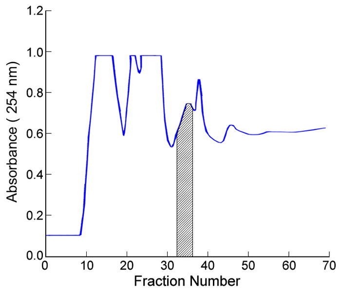
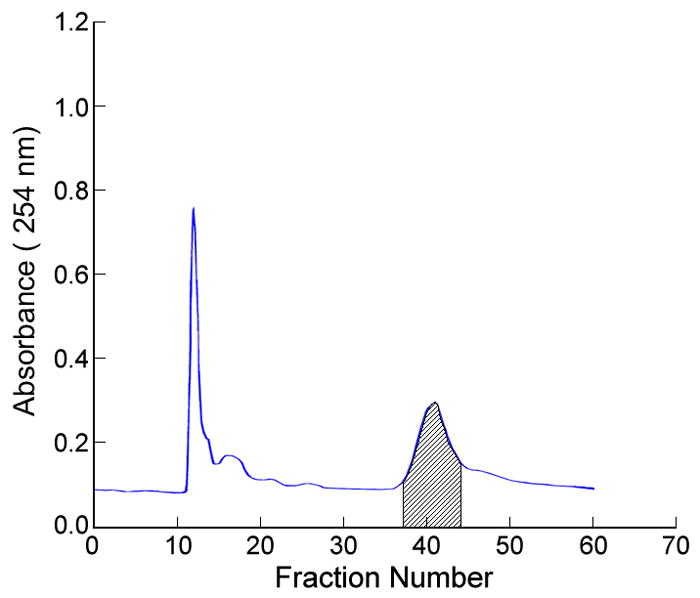
(a) The separation of 400 mg of crude reaction mixture by HSCCC. The shade fractions 33–36 were labeled on the basis of identification of LC-MS. The retention of the stationary phase was about 69.2%. (b) The separation of 7.7 mg of fractions containing the target compounds in the first run by HSCCC. The shaded fractions 37–44 were labeled on the basis of identification of LC-MS. The retention of the stationary phase in this run was about 83.0%. Both of experimental conditions were same as follows: apparatus: model #1HSCCC centrifuge (P.C. Inc., Potomac, MD, USA); column: spiral multilayer coil, 1.6 mm ID and 130 ml capacity; revolution: 800 rpm; flow rate: 2 ml/min; solvent system: hexane/ethyl acetate/methanol/methyl t.-butyl ether/acetonitrile/water (1:1:1:4:4:7, v/v); mobile phase: lower aqueous phase; detection: 275 nm.
In order to further purify 7.7 mg of the fractions collected in the first run, the second separation was performed using the same two-phase solvent system. The column was loaded with 7.7 mg sample dissolved in 4 ml of solvent consisting of equal volumes of each phase. The target compound was eluted in fractions 37–44 (Fig. 4b), where 1 mg of pure product was recovered after vacuum evaporation by freeze-drying. The purity of Cybesin obtained from this second run was 94.0 % at over 95% recovery rate determined by LC-MS (Fig. 5). The retention of the stationary phase in this run was about 83.0%.
Fig. 5.
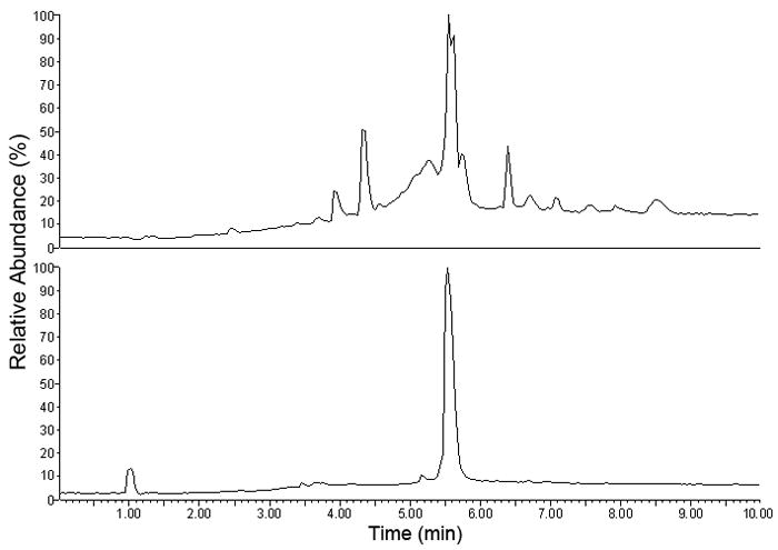
LC-MS analysis of the target compound before and after the second HSCCC purification.
4. Conclusions
The overall results of our studies demonstrated that HSCCC has a great potential for the preparative isolation and purification of Cybesin directly from the crude reaction mixture. Two successive runs with the same two-phase solvent system with the appropriate partition coefficient, 1 mg of pure target compound was obtained at purity of 94.0% from 400 mg of the crude sample. Successful isolation of Cybesin by HSCCC in our present studies indicates that HSCCC is a useful tool for the purification of a minute amount of the target compound from a crude synthetic reaction mixture.
References
- 1.Bugaj JE, Achilefu S, Dorshow RB, Rajagopalan R. J Biomed Opt. 2001;6:122. doi: 10.1117/1.1352748. [DOI] [PubMed] [Google Scholar]
- 2.Pu Y, Wang WB, Tang GC, Zeng F, Achilefu S, Vitenson JH, Sawczuk I, Peters S, Lombardo JM, Alfano RR. Technol Cancer Res Treat. 2005;4:429. doi: 10.1177/153303460500400410. [DOI] [PubMed] [Google Scholar]
- 3.Ye YP, Bloch S, Xu BG, Achilefu S. J Med Chem. 2006;49(7):2268. doi: 10.1021/jm050947h. [DOI] [PMC free article] [PubMed] [Google Scholar]
- 4.Ito Y. J Chromatogr A. 2005;1065:145. doi: 10.1016/j.chroma.2004.12.044. [DOI] [PubMed] [Google Scholar]
- 5.Ito Y, Clary R, Powell J, Knight M, Finn TM. J Liq Chromatogr Rel Technol. 2008;31:1346. doi: 10.1080/10826070802019913. [DOI] [PMC free article] [PubMed] [Google Scholar]
- 6.Ito Y. High-Speed Countercurrent Chromatography. In: Ito Y, Conway WD, editors. Chemical Analysis Series. Vol. 132. Wiley; 1996. pp. 3–44. [Google Scholar]
- 7.Ito Y. CRC Crit Rev Anal Chem. 1986;17:65. [Google Scholar]
- 8.Ito Y. Chromatography. In: Heftmann E, editor. Journal of Chromatography Library. 5. Part A. 51A. Elsevier; 1992. pp. 69–105. Chapter 2. [Google Scholar]
- 9.Conway WD, Ito Y. J Liq Chromatogr. 1984;7:275. [Google Scholar]
- 10.Martin DG. Modern Countercurrent Chromatography. In: Conway WD, Petroski RJ, editors. ACS Symposium Series. 593. American Chemical Society; Washington, DC: 1995. pp. 78–86. [Google Scholar]


