

Abstract
We improved our recently reported retinal OCT system based on transverse priority scanning to achieve high resolution in both the transverse and the axial directions. The implementation of an additional SLO channel enables precise on-line focusing. The system enables imaging of the human retinal cone mosaic off the foveal center without adaptive optics. We demonstrate, for what is believed to be the first time, cone mosaic imaging simultaneously in the scanning laser ophthalmoscope and optical coherence tomography (OCT) channels. OCT B-scan images demonstrate that the cone mosaic is observable in two adjacent layers. Furthermore, we present what are believed to be the first C-scan OCT images of the cone mosaic and show that the major part of light backscattered from below the photoreceptor layer is not guided back toward the pupil by the photoreceptors.
Imaging of the retinal photoreceptor mosaic has attracted considerable interest in recent years. To achieve the required transverse resolution, special flood illumination fundus cameras and scanning laser ophthalmoscopes (SLOs), equipped with adaptive optics (AO) to compensate for ocular aberrations, have been developed.1-4 While these instruments can achieve diffraction-limited resolution, they are rather complex and expensive. It has been demonstrated that retinal cone mosaic imaging is also possible without AO, provided that the imaged eye has low aberrations.5-7 While these techniques provide a transverse resolution of a few micrometers, their depth resolution is much lower, and thus differentiation between retinal layers is not possible.
Optical coherence tomography (OCT)8 provides this depth information, with an axial resolution down to 2–3 μm.9 However, the transverse resolution of retinal OCT is commonly only of the order of ~20 μm, thus preventing one from resolving the cone mosaic spacing (5–10 μm). The poor lateral resolution of the usual retinal OCT systems has two reasons: (i) Most of these systems, both time domain (TD) and spectral domain (SD), are based on A-scans, i.e., they have the fast scanning direction perpendicular to the retinal surface. Fast (TD) or even instantaneous (SD) depth scanning prevents dynamic tracking of the focus and coherence gate. Therefore, these systems use a fixed focus depth, and to avoid blurring of out-of-focus structures they employ small-NA beams to obtain a depth of focus (DOF) that covers the entire retinal thickness. The small NA, however, implies a large focal diameter, preventing high transverse resolution. (ii) If high-NA beams of, e.g., 6 mm diameter, are used, the ocular aberrations cause image blur. To overcome these problems, OCT systems equipped with AO were recently reported.10-12 These systems correct the ocular aberrations associated with the larger sampling beam diameter and sacrifice the blurred information from the out-of-focus layers. By carefully focusing at the photoreceptor layer, a first demonstration of transverse structures of spacing similar to photoreceptors was demonstrated.11,12 These setups, however, are based on A-scans, a technology not suited to obtaining transverse information in both the x and y directions within a short acquisition time, thus preventing motion-artifact-free two-dimensional transverse imaging of the cone mosaic.
A different approach to retinal OCT imaging is transverse-scanning (TS) OCT, a technique that can be combined with SLO.13 We recently developed special variants of TS-OCT in which a highly stable carrier frequency is generated by acousto-optic modulators,14,15 enabling fast image acquisiton. With TS-OCT, a transverse line or plane is imaged before the coherence gate is shifted in depth, thus enabling careful focusing of the imaged plane. A shallow area of interest can be imaged with high resolution in a short time, and unnecessary recording of blurred data outside the DOF range is avoided.
In this Letter we report modifications of our technology that enable imaging of the retinal cone mosaic without AO, perpendicular to the retinal surface (B-scans), as well as parallel to the retinal surface (C-scans). Figure 1 shows a sketch of the instrument. A superluminescent diode (λ0=841 nm, Δλ=51 nm, coherence length =6 μm, power to eye =700 μW) illuminates a Mach–Zehnder interferometer in which the beam is split into a sample and a reference beam. The sample beam illuminates the eye via an xy galvo scanner and a scanning optics (telescope design) that images the pivot point of the scanner into the pupil plane and raster scans the beam over the retina. The reference beam transmits two acousto-optic modulators that generate a net frequency shift of 1 MHz (= carrier frequency). Detectors at both exits of the interferometer enable dual balanced detection. A path delay unit moves the coherence gate step by step into the tissue, an incremental step being performed after a transverse line (or plane) is recorded.
Fig. 1.
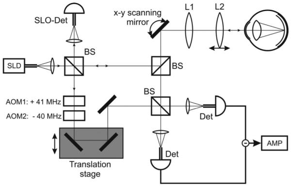
Sketch of the instrument. AMP, amplifier; AOM, acousto-optic modulator; BS, beam splitter; Det, single-mode fiber pigtailed detector; L1 and L2, lenses; SLD, superluminescent diode; SLO-Det, scanning laser ophthalmoscope detector (single-mode fiber pigtailed).
Key elements for cone mosaic imaging are a moderately wide sampling beam (4 mm diameter, enabling transverse resolutions sufficient to resolve the somewhat wider cone spacing at the periphery of the fovea but small enough to avoid excessive ocular aberrations), very small detector aperture sizes (single-mode fibers), an additional confocal SLO detector (also single-mode fiber coupled) that operates in parallel to the OCT channel; and a beam scanning optics with an adjustable focusing lens.
Retinal imaging was performed in three healthy subjects (best corrected visual acuity 1, spherical error ≤2 D, astigmatism ≤0.5 D) at eccentricity ~4° nasal (undilated eye). The three eyes showed similar results, so only images of one eye (spherical error −0.5 D, astigmatism 0.25 D) are shown here. The eye was aligned by transverse positioning of the head until maximum intensity was observed in the SLO channel, then the focusing lens was adjusted until the on-line SLO image showed a cone mosaic of maximum contrast. Two types of OCT/SLO data sets were recorded: B-scan images and C-scan (transverse) images. Figure 2 shows a B-scan image centered at ~4° nasal of the fovea. All the layers known from ultrahigh-resolution OCT9 are visible. Four layers of the posterior retina are labeled from 1 to 4. While there is agreement in the literature that layer 1 is the external limiting membrane and layer 2 is the boundary between the inner and outer photoreceptor layers, there is controversy about layers 3 and 4. In some papers they are regarded as a single structure, the retinal pigment epithelium9 (RPE), while a recent paper described layer 3 as Verhoeff’s membrane and layer 4 as the RPE.12 The association of layer 4 with the RPE is in agreement with our recent findings based on polarization-sensitive OCT.16
Fig. 2.
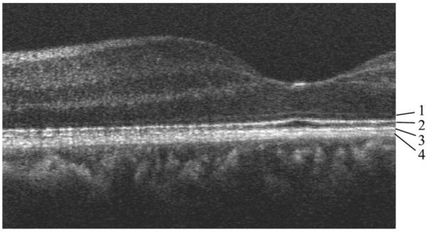
OCT B-scan of human retina centered ~4° nasal. Image size, 2.9 mm (1600 pixels, x) ×1 mm (500 pixels, z, optical depth). The posterior layers are labeled 1 to 4 (see text).
For photoreceptor imaging, we recorded a smaller area of the retina at a higher pixel density. Figure 3 shows the result. In the transverse direction, the image is centered at ~4° nasal, and in the depth direction, it is centered at the posterior retina. Figure 3(a) shows the image obtained in the OCT channel, and Fig. 3(b) shows that obtained simultaneously from the SLO channel. Figure 3(a) provides depth information; the layers labeled 1–4 correspond to those so labeled in Fig. 2. It can clearly be observed that layers 2 and 3 show a regularly spaced transverse structure, especially on the left-hand side of the image. On the right-hand side, the layers are somewhat shadowed by a vessel (arrow). The transverse spacing of the bright reflectors on the left-hand side is ~10 μm. This is somewhat larger than the 1.5 arcmin spacing (~7–8 μm) reported previously for this eccentricity.4 The discrepancy is probably caused by the section’s not being oriented along the line of closest cone spacing. A similar structure in layer 2 (and somewhat less clear in layer 3) was recently observed by use of AO-OCT and attributed to photoreceptors.11 Structures above and below layers 2 and 3 do not show this regular spacing (the signal of layer 1 is too weak for a final judgment as to whether the spacing is present).
Fig. 3.
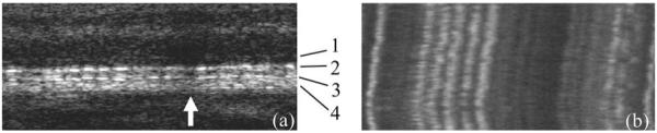
B-scans of human retina centered ~4° nasal. Image size, 200 μm (3500 pixels, x) ×370 μm (185 pixels, z, optical depth). (a) OCT channel (logarithmic intensity scale), layer labeling as in Fig. 2; (b) SLO channel.
Figure 3(b) was obtained from the SLO channel. It provides no depth resolution, i.e., each transverse image line shows the integrated reflectivity over all retinal layers at the given transverse location. The five bright reflectors observed in the left half of layers 2 and 3 of Fig. 3(a) dominate the image of the SLO channel. They are very well visible as parallel, nearly vertically oriented lines, indicating that there was almost no transverse motion of the retina during image acquisition.
Figure 4 shows C-scans obtained at a similar eccentricity. Image size is 200 μm (x)×225 μm (y), (conversion factor17 of 4.68 μm/arcmin), recording time for a single image was 0.2 s. Figures 4(a), 4(c), and 4(e) were obtained from the SLO channel; Figs. 4(b), 4(d), and 4(f), from the OCT channel. Figures 4(a) and 4(b) were obtained with the coherence gate slightly anterior to layers 2/3; Figs. 4(c) and 4(d), approximately at the level of layers 2/3; and Figs. 4(e) and 4(f), slightly posterior to layers 2/3 (approximately at choriocapillaris). The focal plane was kept fixed at the position of maximum cone contrast in the SLO channel. In all of the images obtained with the SLO channel, the cone mosaic is clearly visible. The cone density within the imaged area is ~16,000/mm2, in agreement with previously reported results.1,17 The only OCT image showing a similar structure is Fig. 4(d). The pixel-to-pixel correspondence between the OCT and the SLO channel allows direct identification of similar structures in both images (compare, e.g., the structure within the marked rectangle). The best correspondence between Figs. 4(c) and 4(d) is within the lower bright band of the OCT image [Fig. 4(d)]. In the darker band above, the coherence gate is probably slightly shifted away from the exact position of layer 2 (or 3), caused either by a slight eye movement within the recording time or by a slight curvature of the retina. The intensity variations of individual cones between SLO and OCT channels can be caused by a slight deviation of the coherence gate from the photoreceptor layer and by the different detection schemes. Figures 4(b) and 4(f) show a very different structure. No regularly spaced cones can be observed. This clearly demonstrates the depth discrimination achieved in the OCT channel. Our results also shed some light on the issue of whether light that is backscattered from layers below the photoreceptors is guided through the receptors on their way back to the pupil.18 Since no pronounced correlation between the light distribution coming back from the choriocapillaris [Fig. 4(f)] with the photoreceptor structure of the SLO image [Fig. 4(e)] is observed, we conclude that the major part of that light is not guided by the photoreceptors.
Fig. 4.

Transverse images of human retina centered at ~4° nasal. (a), (c), (e), SLO channel; (b), (d), (f), OCT channel (linear intensity scale). (a), (b), coherence gate slightly above the photoreceptor layer; (c), (d), coherence gate within the photoreceptor layer; (e), (f), coherence gate slightly below the photoreceptor layer.
In conclusion, we have demonstrated that the retinal cone mosaic off the foveal center can be imaged by transverse-scanning OCT without the need for AO, in agreement with earlier SLO-based studies. Our technique provides cross-sectional and transverse information about the cone distribution. In the axial direction, we have shown that the mosaic is visible in two adjacent layers, demonstrating subcellular resolution in vivo. In the transverse direction we found good depth discrimination, and in a layer showing the cone mosaic we observed good correspondence with a parallel-recorded SLO image. Further enhancements of the technique will entail implementation of a fast resonant scanner to improve imaging speed, thus possibly enabling true 3D imaging of the cone mosaic.
Acknowledgments
Financial support from the Austrian Science Fund (FWF grant P16776-N02) is acknowledged.
Footnotes
OCIS codes: 170.4500, 170.4470, 330.5310.
References
- 1.Liang J, Williams DR, Miller DT. J. Opt. Soc. Am. A. 1997;14:2884. doi: 10.1364/josaa.14.002884. [DOI] [PubMed] [Google Scholar]
- 2.Vargas-Martín F, Prieto PM, Artal P. J. Opt. Soc. Am. A. 1998;15:2552. doi: 10.1364/josaa.15.002552. [DOI] [PubMed] [Google Scholar]
- 3.Hofer H, Chen L, Yoon GY, Singer B, Yamauchi Y, Williams DR. Opt. Express. 2001;8:631. doi: 10.1364/oe.8.000631. [DOI] [PubMed] [Google Scholar]
- 4.Roorda A, Romero-Borja F, Donnelly WJ, Queener H, Hebert TJ, Campbell MCW. Opt. Express. 2002;10:405. doi: 10.1364/oe.10.000405. [DOI] [PubMed] [Google Scholar]
- 5.Miller DT, Williams DR, Morris GM, Liang J. Vision Res. 1996;36:1067. doi: 10.1016/0042-6989(95)00225-1. [DOI] [PubMed] [Google Scholar]
- 6.Wade AR, Fitzke FW. Lasers Light Ophthalmol. 1998;12:129. [Google Scholar]
- 7.Vohnsen B, Iglesias I, Artal P. Opt. Lett. 2004;29:968. doi: 10.1364/ol.29.000968. [DOI] [PubMed] [Google Scholar]
- 8.Huang D, Swanson EA, Lin CP, Schuman JS, Stinson WG, Chang W, Hee MR, Flotte T, Gregory K, Puliafito CA, Fujimoto JG. Science. 1991;254:1178. doi: 10.1126/science.1957169. [DOI] [PMC free article] [PubMed] [Google Scholar]
- 9.Drexler W. J. Biomed. Opt. 2004;9:47. doi: 10.1117/1.1629679. [DOI] [PubMed] [Google Scholar]
- 10.Hermann B, Fernández EJ, Unterhuber A, Sattmann H, Fercher AF, Drexler W, Prieto PM, Artal P. Opt. Lett. 2004;29:2142. doi: 10.1364/ol.29.002142. [DOI] [PubMed] [Google Scholar]
- 11.Zhang Y, Rha J, Jonnal RS, Miller DT. Opt. Express. 2005;13:4792. doi: 10.1364/opex.13.004792. [DOI] [PubMed] [Google Scholar]
- 12.Zawadzki RJ, Jones SM, Olivier SS, Zhao M, Bower BA, Izatt JA, Choi S, Laut S, Werner JS. Opt. Express. 2005;13:8532. doi: 10.1364/opex.13.008532. [DOI] [PMC free article] [PubMed] [Google Scholar]
- 13.Rogers JA, Podoleanu AG, Dobre GM, Jackson DA, Fitzke FW. Opt. Express. 2001;9:533. doi: 10.1364/oe.9.000533. [DOI] [PubMed] [Google Scholar]
- 14.Hitzenberger CK, Trost P, Lo P-W, Zhou Q. Opt. Express. 2003;11:2753. doi: 10.1364/oe.11.002753. [DOI] [PubMed] [Google Scholar]
- 15.Pircher M, Goetzinger E, Leitgeb R, Hitzenberger CK. Phys. Med. Biol. 2004;49:1257. doi: 10.1088/0031-9155/49/7/013. [DOI] [PubMed] [Google Scholar]
- 16.Pircher M, Götzinger E, Leitgeb R, Sattmann H, Findl O, Hitzenberger CK. Opt. Express. 2004;12:5940. doi: 10.1364/opex.12.005940. [DOI] [PubMed] [Google Scholar]
- 17.Curcio CA, Sloan KR, Kalina RE, Hendrickson AE. J. Comp. Neurol. 1990;292:497. doi: 10.1002/cne.902920402. [DOI] [PubMed] [Google Scholar]
- 18.Choi SS, Doble N, Lin J, Christou J, Williams DR. J. Opt. Soc. Am. A. 2005;22:2598. doi: 10.1364/josaa.22.002598. [DOI] [PubMed] [Google Scholar]