

Abstract
A general method for construction of three dimensional structures by directed assembly of microscale polymeric sub-units is presented. Shape-controlled microgels are directed to assemble into different shapes by limiting their movement onto a molded substrate. The capillary forces, resulting from the presence of a liquid polymer, assemble the microgels in close contact with the rest of the units and with the free surface, the latter imposing the final geometry of the resulting construct. The result is a freestanding structure composed of one or multiple layers of sub-units assembled in a tightly packed conformation. The applicability of the technique for the construction of scaffolds with cell-laden sub-units is demonstrated. In addition, scaffolds formed by the sequential aggregation of sub-units are produced.
The formation of complex structures through self-regulating aggregation of smaller sub-units is a strategy broadly observed in nature; from the cytoskeletal structure within cells to the formation of coral reefs. Self-assembly is driven by the attempt of a system to minimize its energy by spontaneous assembly of individuals units. The process of self-assembly is characterized by the formation of complex structures via the spontaneous combination of discrete small sub-units at an energy minimum.
Self-assembly process could be categorized based on the size of the units into “molecular self-assembly” and “mesoscale self-assembly” (MESA) [1]. Technologies based on MESA have emerged as a promising approach for the spontaneous construction of several shapes with a large number of materials. Potential applications include microelectronics, MEMS, sensors and micro-analytical devices [2]. Additionally, tissue engineering can potentially benefit from MESA, where bottom-up assembly of building blocks containing cells can be used to engineer artificial tissues [3]. For example, cell-laden sub-units have been assembled to form tissues with high spatial resolution by using both MESA [4] and microfluidics [5].
Most MESA approaches use hydrophilic-hydrophobic interactions to assemble the sub-units. However, a major limitation of this approach is that it can only be used to generate a limited number of shapes that are defined by the boundaries between the different phases [6]. In this work, we introduce a technique where a surface, acting as a template, partially restricts the subunits by confining them and direct the assembly process. In particular, we used polydimethylsiloxane (PDMS), a versatile and widely used elastomeric material that can easily be molded to replicate the shape and topography of many structures in 2D and 3D [7].
As presented in Figure 1, microgels made with specific shapes were mixed in a pre-polymer solution (Figure 1A) and spread on a PDMS surface (Figure 1B). During this process, the liquid wets the surface and drags the microgel sub-units as it covers the PDMS template (Figure 1C). Upon removal of the excess pre-polymer (e.g. by pipetting or by using an absorbent material), microgels assemble due to the capillary forces of the remaining pre-polymer. In seeking the point of minimum energy the microgels closely pack to form a “brick wall”-like structure on the surface of the template. Since the units are confined to the PDMS surface, the final structure generates a positive replica of the PDMS template (Figure 1D). To stabilize the resulting assembly, the structure was illuminated a second time to crosslink the polymer remaining between the units. This generated a mechanically robust structure that could be separated from its PDMS template (Figure 1E).
Figure 1. Schematic diagram of the micro-masonry assembly process.
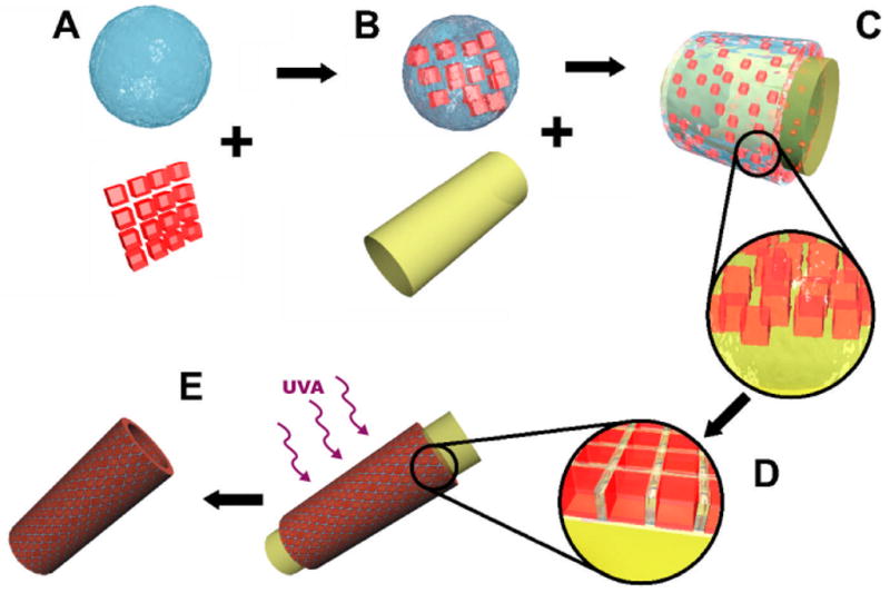
Microgels of desired shapes were produced by photolithography and mixed with a solution containing the pre-polymer (A). The solution was poured on the surface of a high affinity PDMS mold (B) where it spread on the PDMS surface (C). The removal of the excess pre-polymer solution induced a further packing of the microgels (D). The system was exposed to light to crosslink the pre-polymer remaining by the units and the structure was subsequently separated from the PDMS surface (E)
In contrast to the previously reported examples of MESA, the technique presented here can be used to construct a range of shapes. In this paper we generate a small number of shapes that we consider relevant for biological applications, or those unable to be obtained by any other technique, such as a tube, a casquet (i.e. empty semi-sphere) and a solid “sphere” (Figure 2).
Figure 2. Structures constructed with microgel units by using micro-masonry.
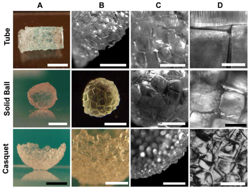
The first row presents a 5mm in diameter and 1cm long tube composed of transparent and green units [Bar in A=5mm]. In image B [Bar=4mm] the edge of the tube can be observed with detail, while in C and D [Bars are 2mm and 500μm respectively] the wall of the tube is photographed with increasing magnification. The aggregation of the units in absence of a mold and in a hydrophobic environment forms a solid 6mm diameter sphere presented in the second row [Bars in A and B are 3 and 4mm respectively]. The close packing can be seen in C [Bar=2mm] and D [Bar=1mm]. The third row is composed of images of a semi-spherical casquet with a 1cm diameter. The general view of the freestanding structure [Bar in A is 12mm] reveals a close packing of the units [Bar in B is 4mm]. The crass-section of the monolayer formed by the units can be observed in C [Bar=3mm]. In D the packing shows some non cubic sub-units [Bar=1.5mm].
To show the utility of the PDMS template we demonstrated the non-template based aggregation of microgels in a hydrophobic fluid. The sphere is an example of self-aggregation of hydrophilic blocks in a hydrophobic media. In contrast with the other examples in Figure 2, it was made in absence of a mold. In this process, as the units were introduced in a low density hydrophobic media (i.e. mineral oil), they spontaneously assembled into a compact sphere that lowered their interface area in contact with the oil.
By introducing a surface to direct the assembly, a range of other shapes were fabricated. As an example, a hollow tube-like structure was fabricated by using the surface of a PDMS column (3 mm (d) × 1 cm (h)) as a template for microgel assembly. Initial trials of direct absorption of the building blocks in prepolymer solution showed a preferred aggregation on the PDMS surface. This tendency increased as the gels were mechanically forced into close contact with the surface. When the excess prepolymer was removed, the blocks remained on the PDMS surface and were compacted because of the capillarity action of the remaining prepolymer between the blocks.
A limitation using a hydrophobic PDMS surface is that in some cases the resulting microgel assembly was discontinuous and composed of groups of building blocks. These results were greatly enhanced when a PDMS surface with high affinity to the PEG solution was employed. To achieve this, we oxidized the PDMS surface with air plasma [8] to increase the spreading of the sub-units in the solution on the surface in addition to their tendency to form a monolayer. Any remaining local defects could be easily removed mechanically. The elimination of the excessive prepolymer producing the compact aggregation followed by a short UVA treatment (5s) gave rise to the tube in Figure 2. To verify the possibility of using a mixture of different sub-units, some of the microgels were stained green and randomly incorporated into the tubular structure.
For the fabrication of the casquet in Figure 2, a hydrophilic (i.e. oxidized) PDMS surface was employed. As in the previous case, the surface was wetted with a drop of pre-polymer solution containing microgel sub-units. A small agitation of the entire system provided sufficient energy to spontaneously assemble the microscale cubes, resulting in the formation of a monolayer of units on the surface (Figure 2C). As previously, the excess liquid pre-polymer was removed and the resulting structure was stabilized by a secondary cross-linking step.
Interestingly, the quality of the aggregation improved as the building blocks were immersed in a hydrophobic solution before the secondary crosslinking step. This “forced” the microgels against the PDMS surface and reduced the probability of overlapping.
Several factors such as capillarity, media viscosity and hydrophobicity of the template affect the assembly of the block units. For example, capillary forces limit the movement of the block units to the surface of the PDMS and drive the assembly process. In particular, upon removal of the excess prepolymer, the remaining solution between the microgels forms numerous capillary bridges between adjacent blocks, sticking them together [9]. In comparison with those MESA techniques where surface adhesion between different units is the main driving force [6], here the microgel assembly is driven by the template geometries and capillary force. The hydrophilic characteristics of the sub-units promote the capture of water (and the consequent growth of the capillary bridges) increasing the binding effect of the water due to capillary forces [10].
In addition to the surface modification of the PDMS discussed above, the dissolved polymer chains played a fundamental part in the aggregation. Units dissolved in PEG/PBS solution tended to join strongly with PDMS and other units; but when units are dissolved in PBS only, aggregation was much weaker and in most cases insufficient for reliable assembly process. This observation agrees with those in hydrophobic driven self-assembly of PEG [11], where more compact aggregates were observed in presence of pre-polymer solution instead of only PBS, an effect produced because the soluble polymer chains intermingle fully and the solution thickens and become more viscous, increasing its resistant to the movement of the adjacent blocks [12].
As an example of the proposed MESA process we demonstrated its use in the assembly of cell-laden microgels. Numerous techniques exist to fabricate 3D tissue-like structures with complex microarchitectures, such as organ printing [13], multilayered photopatterning [14] and microfabricated scaffolds [15]. Technologies based on direct assembly are simple and scalable, making them useful for tissue engineering. Furthermore, since tissues are made from repeating functional tissue units (e.g. liver and renal lobules), the use of cell-laden units for the construction of a functional organ piece-by-piece presents a bioinspired approach that may be able to create tissue-like structural complexity. Previous studies have demonstrated the long-term viability and metabolic activity of cells encapsulated in PEG based hydrogels [16, 17]. These studies show that, even if the photoinitiator employed has an almost null toxicity [18], the photolithography process may induce cell death because the free radicals generated by the UVA radiation [19]. Therefore, decrease cell mortality when fabricating cell-laden units involves the minimization of the crosslinker amount and the UV time [20]. Here, to validate the utility of this process in biological applications, we analyzed the cell survival and death after the encapsulation and the assembly process.
As shown in Figure 3, hepatocyte-laden microgel sub-units of 0.5×0.5×0.5mm were assembled to form a 5mm in diameter and 1 cm long tube. The cells were stained with an EthD-1/Calcein assay to indicate the live (green) and dead (red) cells. As it can be seen, a large fraction of cells remained viable after the assembly and secondary crosslinking processes. Upon quantification the average survival rate of cells was 83.1±2.3% after the encapsulation.
Figure 3. Hepatocytes encapsulated in PEG microgels assembled to form a 5mm diameter tube.

Image A is a general view of the tube formed by aggregated cubic units, living cells are marked in green while those dead (or dying) appear in red [Bar=1.5mm]. In (B) a magnified image of the sub-units forming the tube opening is shown. The junction between adjacent building blocks forming the tube wall, is shown in (C). [Bars in B and C are 400μm]
While the present technique is applicable to a wide range of materials, PEG was chosen because of its ability to form gels and its widespread use in bio-related applications. A key limitation with most cell-laden hydrogels is the diffusion of the gas/nutrients through the polymer, which limit the maximum size of the units. For example, PEG gels thicker than 1mm have shown high viability in their periphery and lower cell viability at the core, because transport limitations inevitably end in the necrosis of the inner cells [21]. Therefore, the results may benefit from the use of smaller polymer units that will, in addition, increase the resolution of the assembly process. Besides the tissue-like structures, other applications such as drug delivery or electronics can potentially benefit from this technique [22]
To investigate the ability of the technique to generate large structures for smaller sub-units, we produced a 3mm diameter tube formed by 100μm side cubic units (Figure 4A and B). With the coarse photolithographic technique that was employed, we have found that, sub-units were pyramid-like while increasing the radiation time produced a connected layer of cross-linked polymer in between the sub-units. Despite the irregular shape of the sub-units, the aggregation remained effective with the only difference in observation being a more disordered appearance of the tube wall surface (Figure 4B).
Figure 4. Micromasonry by using multi-layered, lock-and-key and 100μm microgel sub-units assemblies.
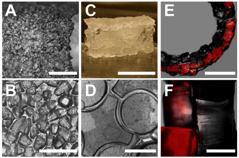
Images correspond to different 5mm diameter tubes. A shows a tube composed of 100μm sub-units [Bar=1.5mm]. Because of the irregularity of the sub-units, the tube wall has a disordered appearance which can be observed in B [Bar=0.25mm]. C is a tube formed piece-by-piece by 1mm complementary sub-units [Bar=5mm]. The assembly of lock-and-key sub-units can be observed in D [Bar=1mm]. E is a phase/fluorescence superposition image of a tube composed of two layers of 500μm sub-units with Nile-red stained blocks being used for the outer layer [Bar=2.5mm]. F is a more detailed image of the walls, where the interface can be clearly observed [Bar=0.5mm].
We also demonstrated that larger scaffolds were fabricated by using a layer-by-layer approach. In Figure 4E we used a 5mm in diameter PDMS tube to generate a tube made from 500μm sub-units. To demonstrate that the process can be used to generate multi-layered structures, a layer of Nile-red labeled subunits were assembled on the preformed tube. The process, that can be repeated to produce subsequent layers, was similar to the one employed above with the PDMS support. This demonstrates the scalability of the technique and the possibility to reproduce the coaxial structures broadly observed in technology and biology (e.g. in vascular vessels).
In biological applications, the speed and autonomy of the self-aggregation are crucial while small defects on the surface (i.e. sub-units dislocations) are tolerable. However the surface driven assembly technique can also be employed to aggregate the pieces forming the scaffold one by one, providing a precise and error-free result with the possibility of employing non-symmetric sub-units. The process is similar to the one used above with the exception of the sub-units, instead of being deposited in solution, were trapped on a wet surface one by one, with the assembly being driven by the capillary forces. The result of the self-assembly of a 6mm diameter and 1cm long tube composed of 1mm complementary sub-units is presented in Figure 4C. In Figure 4D the characteristics of the wall can be seen in more detail with some of more than 350 complementary sub-units forming the tubular scaffold being imaged.
Having precise control of the position of each sub-unit results in a more time-consuming process that is particularly suitable for “inert” components (e.g. electronic technologies). While the self-assembling of a tube formed by highly symmetrical sub-units (i.e. cubes) was achieved in a few minutes, the production of the tube in the Figure 4C took more than three hours. The repetitive process however, would greatly benefit from a robotic implementation which can provide the advantage of high 3D spatial resolution to cell-laden scaffolds.
The technique presented here is highly robust and, despite inhomogeneous spreading of the polymer and shape variations in the sub-units, the reliability of the technique corrects defects by the adjacent sub-units or by the liquid prepolymer.
We have presented a template-based technique for the formation of macroscopic structures by the 3D aggregation of shape-controlled microgels. A broad range of fields can profit from the construction of 3D structures microscale resolution, such as microlectronics, analytical devices and tissue engineering. Future work in this field will involve the use of the engineered structures for generating biological tissues. For technological applications, such as 3D electrical circuits, future work will be directed to the inclusion of physical cues (e.g. magnetic and electric domains) in the sub-units.
Experimental
The shape controlled microgels were produced by entrapping a solution of 0.5%(w/w) photoinitiator and 20%(w/w) PEG-dimethacrylate in PBS between a PDMS surface and a negative photomask. The space between both surfaces, controlled by glass spacers, gave the final thickness of the produced microgels. The illumination with a UVA for 12 seconds through the photomask crosslinked the exposed regions and the removal of the uncrosslinked polymer resulted in a set of freestanding PEG cubes. In the case of cell laden microgels, HepG2 cells were suspended at a concentration of 105 cell/ml in the pre-polymer solution and the gels were fabricated as described above.
The microgels and the pre-ploymer solution were spread on the surface of the hydrophilic PDMS mould. The excess of prepolymer was removed with an absorbent material and the remained polymer forced the microgels to a close packing. A 5s UVA illumination crosslinked the whole structure, which was then separated from the PDMS template.
(More details of the experiments can be found in the Supporting Information)
Supplementary Material
Acknowledgments
We thank K. Kareh and Dr. C. Hutson for the comments on the manuscript and Dr. Y. Du for scientific discussions and help. This work was supported by the National Institutes of Health (EB007249; DE019024; HL092836), the National Science Foundation CAREER award and Institute for Soldier Nanotechnology.
Footnotes
Author contributions: JGF and AK conceived of the project. JGF designed and performed the experiments. JGF and AK analyzed and interpreted the results and wrote the manuscript.
References
- 1.Bowden N, Terfort A, Carbeck J, Whitesides GM. Science. 1997;276:233. doi: 10.1126/science.276.5310.233. [DOI] [PubMed] [Google Scholar]
- 2.Terfort A, Bowden N, Whitesides GM. Nature. 1997;386:162. [Google Scholar]
- 3.Nichol JW, Khademhosseini A. Soft Matter. 2009;5:1312. doi: 10.1039/b814285h. [DOI] [PMC free article] [PubMed] [Google Scholar]
- 4.Du Y, Lo E, Ali S, Khademhosseini A. Proceedings of the National Academy of Sciences. 2008;105:9522. doi: 10.1073/pnas.0801866105. [DOI] [PMC free article] [PubMed] [Google Scholar]
- 5.Cheung YK, Gillette BM, Zhong M, Ramcharan S, Sia SK. Lab on a Chip. 2007;7:574. doi: 10.1039/b700869d. [DOI] [PubMed] [Google Scholar]
- 6.Clark TD, Tien J, Duffy DC, Paul KE, Whitesides GM. Journal of the American Chemical Society. 2001;123:7677. doi: 10.1021/ja010634l. [DOI] [PubMed] [Google Scholar]
- 7.LaFratta CN, Li L, Fourkas JT. Proceedings of the National Academy of Sciences. 2006;103:8589. doi: 10.1073/pnas.0603247103. [DOI] [PMC free article] [PubMed] [Google Scholar]
- 8.Vickers JA, Caulum MM, Henry CS. Analytical Chemistry. 2006;78:7446. doi: 10.1021/ac0609632. [DOI] [PubMed] [Google Scholar]
- 9.Scheel M, Seemann R, Brinkmann M, Di Michiel M, Sheppard A, Breidenbach B, Herminghaus S. Nat Mater. 2008;7:189. doi: 10.1038/nmat2117. [DOI] [PubMed] [Google Scholar]
- 10.Fisher LR, Israelachvili JN. Colloids and Surfaces. 1981;3:303. [Google Scholar]
- 11.Du Y, Lo E, Vidula M, Khabiry M, Khademhosseini A. Cellular and Molecular Bioengineering. 2008;1:157. doi: 10.1007/s12195-008-0020-z. [DOI] [PMC free article] [PubMed] [Google Scholar]
- 12.Kendall K. Molecular Adhesion and Its Applications. Kluwer Academic; New York: 2001. p. 103. [Google Scholar]
- 13.Mironov V, Boland T, Trusk T, Forgacs G, Markwald RR. Trends in Biotechnology. 2003;21:157. doi: 10.1016/S0167-7799(03)00033-7. [DOI] [PubMed] [Google Scholar]
- 14.Gallego D, Ferrell N, Sun Y, Hansford DJ. Materials Science and Engineering: C. 2008;28:353. [Google Scholar]
- 15.Fernandez JG, Mills CA, Samitier J. Small. 2009;5:614. doi: 10.1002/smll.200800907. [DOI] [PubMed] [Google Scholar]
- 16.Weber LM, He J, Bradley B, Haskins K, Anseth KS. Acta Biomaterialia. 2006;2:1. doi: 10.1016/j.actbio.2005.10.005. [DOI] [PubMed] [Google Scholar]
- 17.Koh WG, Pishko M. Analytical and Bioanalytical Chemistry. 2006;385:1389. doi: 10.1007/s00216-006-0571-6. [DOI] [PubMed] [Google Scholar]
- 18.Bryant SJ, Nuttelman CR, Anseth KS. Journal of Biomaterials Science, Polymer Edition. 2000;11:439. doi: 10.1163/156856200743805. [DOI] [PubMed] [Google Scholar]
- 19.Pfeifer GP, You YH, Besaratinia A. Mutation Research/Fundamental and Molecular Mechanisms of Mutagenesis. 2005;571:19. [Google Scholar]
- 20.Liu VA, Bhatia SN. Biomedical Microdevices. 2002;4:257. [Google Scholar]
- 21.Tsang VL, Chen AA, Cho LM, Jadin KD, Sah RL, DeLong S, West JL, Bhatia SN. FASEB J. 2007;21:790. doi: 10.1096/fj.06-7117com. [DOI] [PubMed] [Google Scholar]
- 22.Gracias DH, Tien J, Breen TL, Hsu C, Whitesides GM. Science. 2000;289:1170. doi: 10.1126/science.289.5482.1170. [DOI] [PubMed] [Google Scholar]
Associated Data
This section collects any data citations, data availability statements, or supplementary materials included in this article.