Abstract
Fimbriae and pili are macromolecular structures on the surface of Gram negative bacteria that are important for cellular adhesion. A 2.7 Å resolution crystal structure of a complex of E. coli fimbrial proteins containing FimH, FimG, FimF, and FimC provides the most complete model to date for the arrangement of subunits assembled in the native structure. The first three proteins form the tip of the fimbriae while FimC is the chaperone protein involved in the usher/chaperone assembly process. The subunits interact through donor strand complementation where a β-strand from a subunit completes the β-sandwich structure of the neighboring subunit or domain closer to the tip of the fimbria. The function of FimC is to provide a surrogate donor strand before delivery of each subunit to the FimD usher and the growing fimbria. Comparison of the subunits in this structure and their chaperone-bound complexes show that the two FimH domains change their relative orientation and position in forming the tip structure. Also, the non-chaperone subunits undergo a conformational change in their first β-strand when the chaperone is replaced by the native donor strand. Some residues move as much as 14 Å in the process. This structural shift has not been noted in structural studies of other bacterial adhesion sub-structures assembled via donor strand complementation. The domains undergo a significant structural change in the donor strand binding groove during fimbrial assembly, and this likely plays a role in determining the specificity of subunit-subunit interactions among the fimbrial proteins.
Keywords: FimH, cell adhesion, donor strand exchange, donor strand complementation, usher/chaperone assembly
Introduction
Gram negative bacteria such as E. coli possess non-flagellar adhesive appendages on their surface, the tips of which have receptor sites that allow the bacterium to bind cell types providing appropriate ligands. Chaperone/usher pili or fimbriae (Fronzes et al., 2008), one of the five classes of these appendages, are formed by families of gene products. Fim proteins form type 1 fimbriae, Pap proteins form type P pili, and other families, such as CS1, CFA/I and the Dra adhesins, form fibrillar or rod-like structures. In the case of type 1 fimbriae, the tip protein is FimH which contains a lectin domain for binding mannose derivatives on the surface of neighboring cells and a pilin domain that provides a link to the rest of the fimbria. Each domain has the folding topology of an immunoglobulin domain, i.e., a pair of β-sheets arranged in a sandwich. The pilin domain and other Fim subunits differ from the typical immunoglobulin fold in that one of the β-strands is missing, thus producing a groove along the length of the domain. This groove provides a binding site for a β-strand from the next protein subunit in the fimbria and is associated with most of the interactions joining the subunits. The donor strand and groove make up the donor strand complementation (DSC) structural motif.
Donor strand complementation, while a very effective way of providing strong inter-molecular linkages, presents interesting control and regulation problems for the assembly of these kinds of structures. These are handled by a chaperone/usher system involving two proteins, FimC (the chaperone) and FimD (the usher). FimC binds to individual copies of FimH, FimG, FimF, and FimA and delivers them to FimD for assembly of the extracellular fimbria. A polypeptide strand of FimC is inserted into the open groove of the accompanying subunit and is important for proper folding of the incomplete IgG fold (Barnhart et al., 2000). The assembly process requires replacement of the FimC strand by the donor strand from the next subunit added to the growing fimbria in a mechanism called donor strand exchange (DSE).
The fimbrial and type P pilus systems have been well studied, biochemically and structurally. X-ray crystallographic and NMR structures are available for a number of the subunits in complex with their chaperones (Choudhury et al., 1999; Eidam et al., 2008; Hung et al., 2002; Sauer et al., 2002; Verger et al., 2007; Zavialov et al., 2003; Zavialov et al., 2005) and in complex with β-strands forming or mimicking the subunit-subunit interactions found in the assemblies (Gossert et al., 2008; Puorger et al., 2008; Sauer et al., 2002; Verger et al., 2007; Zavialov et al., 2005). A number of structural changes associated with DSE have been described in previous structures. The crystal structures of PapA (Verger et al., 2007) and Caf1 (Zavialov et al., 2003; Zavialov et al., 2005) contain pairs of subunits held together by donor strand complementation, but with one of the subunits also interacting with its chaperone protein. The subunit bound to the chaperone appears to be trapped in an incompletely-folded structure with loose packing of residues in the core of the subunit. The subunit bound to the native donor strand is more tightly packed, and the stabilization obtained by the packing rearrangement is believed to drive the assembly process (Sauer et al., 2002; Zavialov et al., 2003).
We recently solved a crystal structure of a complex containing FimH, FimG, FimF and FimC, part of which forms the tip of the fimbriae (Le Trong et al., 2010) (PDB identifier 3JWN). This structure provides the most complete model to date for how subunits assemble into fimbriae. We describe here the structural differences between the subunits in the native tips and in their FimC complexes pointing out how the molecular structures change in response to DSE.
Methods
Experimental details concerning the crystal structure of the fimbrial tip complex are presented elsewhere (Le Trong et al., 2010), so only a brief summary is presented here to permit an assessment of the structural model being analyzed. Fimbrial tips were obtained by expressing a plasmid containing genes for FimC, FimF, FimG and FimH in E. coli, Cells were harvested and disrupted using a French press, and the complex was purified on Ni-NTA-agarose (Qiagen). Elution of a FimC-His6-FimFGH-containing fraction, followed by affinity chromatography on an α-D-mannose-agarose column and fractionation on a Superdex 75 gel filtration column resulted in a sample suitable for crystallization. Crystals were obtained by mixing equal volume drops containing the protein (11 mg/ml in 20mM Hepes pH 7.0; 0.15M NaCl) and a crystallization solution containing 1.6M KCl, 0.1M sodium citrate pH 4.1.
Diffraction data were collected at ALS Beamline 5.0.2 and processed with HKL2000 (Otwinowski and Minor, 1997). The space group for the crystals is R32 with two copies of the tip complex in the asymmetric unit. A 2.7 Å resolution data set (Rmerge=0.147, <I>/<σ(I)>=14.0, completeness=90.6%, redundancy=9.5) was used for molecular replacement calculations with Phaser (McCoy et al., 2007), MOLREP (Vagin and Teplyakov, 1997), and EPMR (Kissinger et al., 1999). Input structures were those known for FimG (Puorger et al., 2008) (PDB identifier 3BFQ), FimF (Eidam et al., 2008) (PDB identifier 3BWU), and FimC (Eidam et al., 2008) (PDB identifier 3BWU). The known structure of FimH (PDB identifier 1KLF) (Hung et al., 2002) could not be easily placed with the molecular replacement programs, but the difference electron density was clear enough to place the FimH domains manually and to optimize their positions using the real space refinement capabilities of XtalView (McRee, 1999).
The structural model was refined using REFMAC5 (Murshudov et al., 1997) in the CCP4 suite (Collaborative Computational Project, 1994). Rfree (Brünger, 1993) was calculated using 5% of the data in the test set. Sigma A weighted |Fo|-|Fc| and 2|Fo|-|Fc| electron density maps (Read, 1986) were viewed with XtalView (McRee, 1999) and Coot (Emsley and Cowtan, 2004). The R for the final model is 0.245, Rfree is 0.274, and the rms deviation from ideal bond lengths is 0.005 Å. Coordinates and structure factors have been deposited in the Protein Data Bank with identifier 3JWN. 88% of the residues are in most-favored regions in a Ramachandran plot. 11.2% were in additional allowed regions, 0.25 in generously allowed regions, and 0.6% in disallowed regions. MOLSCRIPT (Kraulis, 1991), and Raster3d (Merritt and Bacon, 1997) were used to produce Figures 1-4, 7, and 8.
Figure 1.
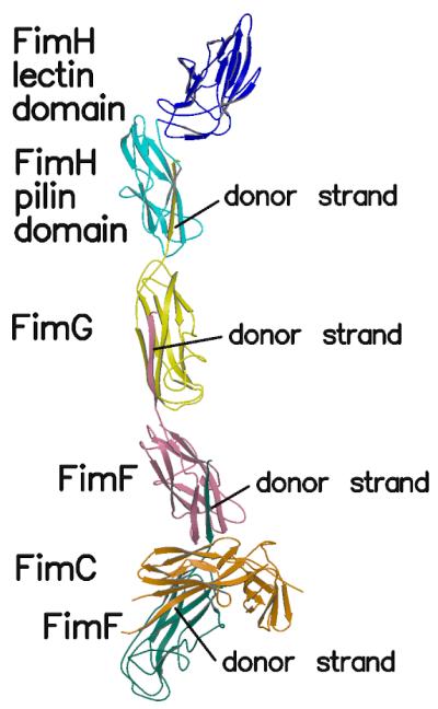
Overall view of the structure of the complex. The FimH lectin domain is shown in blue, the FimH pilin domain in cyan, FimG in yellow, FimF in pink, FimF (chain E) in teal and FimC in orange.
Figure 4.
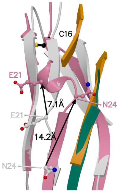
Superposition of the FimF domains bound to the donor strand (this structure) and FimC (PDB entry 3BWU). FimF in pink, FimF (chain E) donor strand in teal, FimF/FimC (3BWU) in grey, FimC (3BWU) in orange. Black arrows and distances show shifts in Cα positions between FimF and FimF/FimC for selected residues.
Figure 7.
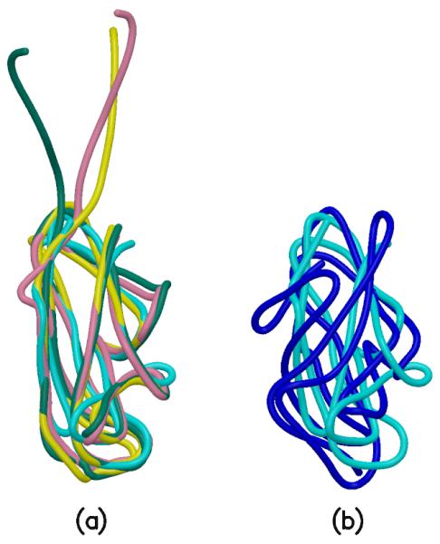
Superpositions of the domains. (a). FimH pilin domain in cyan, FimG in yellow, FimF in pink, FimF (chain E) in teal. These four domains have very similar folds. (b). FimH lectin domain in blue and FimH pilin domain in cyan. These two domains do not superpose as well as those in Figure 7(a). Coot (Emsley and Cowtan, 2004) and SSM (Krissinel and Henrick, 2004) were used for the superpositions. Superposition of FimG on the FimH pilin domain resulted in an rmsd of 1.734 Å for 108 Cα atoms. For FimF and FimH (pilin domain), the rmsd is 1.717 Å for 110 Cα atoms, and for FimF (chainE) and FimH (pilin domain), the rmsd is 2.285 Å for 107 Cα atoms. Superposition of the FimH lectin and pilin domains gave an rmsd of 3.492 Å for 95 Cα atoms.
Figure 8.
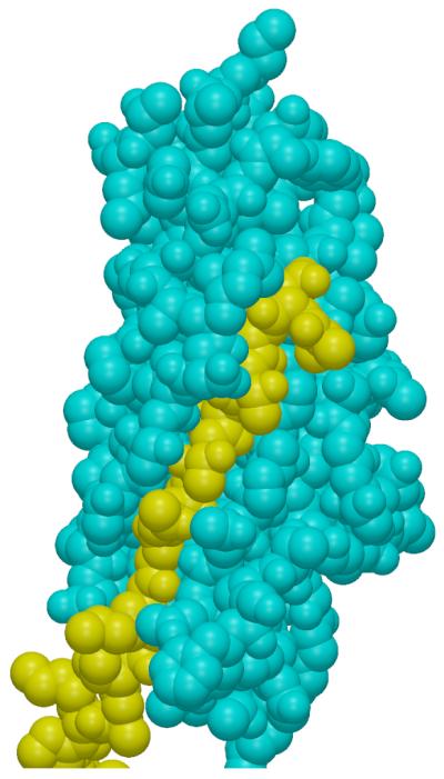
Van der Waals surfaces for the FimH pilin domain (cyan) and the FimG donor strand (yellow).
Results
Overview of the Tip Structure
The structure of one of the two tip complexes in the asymmetric unit is shown in Figure 1 (Le Trong et al., 2010). A single complex contains one copy of FimH, one of FimG, two of FimF, and one of FimC. The lectin domain of FimH is found at one end of the fimbrial tip, and FimC, the chaperone protein involved in the usher mechanism, is near the other end of the complex, the end closest to the fimbrial stalk. Each subunit, and each of the two domains in FimC and FimH, is an immunoglobulin-like sandwich structure made up of two β-sheets. For the pilin domain of FimH, FimG, and one of the FimF subunits, one of the β-strands in the sheets is the N-terminal extension of the next subunit added to the fimbria (Figure 1). Thus the N-terminus of FimG is bound to the pilin domain of FimH, the N-terminus of FimF is included in the FimG domain, and the N-terminus of the second FimF in the complex (chain E in the deposited PDB file) contributes a β-strand to the first FimF domain (chain F).
This oligomeric arrangement is terminated by the binding of FimC to the last FimF (chain E). The fact that this complex contains only a single FimC subunit complementing the β sheet of the last FimF confirms the hypothesis that FimC is displaced from each subunit during pilogenesis through donor strand exchange. It is unclear what mechanism allows the second FimF subunit, but not a third, to incorporate into the complexes that were crystallized. The presence of two FimF molecules in the complex was unexpected and remains unexplained. The multi-subunit complex found in this crystal form is the largest fimbrial sub-assembly crystallized to date and provides a view of the fimbrial tip consistent with other experimental evidence (Aprikian, et al., in preparation).
The two copies of the complex in the asymmetric unit of PDB entry 3JWN are nearly identical with only small differences in the arrangement of the subunits and the conformations of a few loops between β-strands. The two copies are situated in different crystal packing environments and are thus not related by crystallographic symmetry. Superposition of 929 Cα atoms common to each complex gives an rmsd of 1.26 Å. The following discussion will focus on one of the complexes (chains H,G,F,E, and C in PDB entry 3JWN).
For the following structure comparisons, subunits or domains not associated with the FimC chaperone will be denoted by names such as FimH or FimF. The complexes with the chaperone will be denoted as FimH/FimC and FimF/FimC. Each fimbrial tip complex in the deposited model (3JWN) contains two copies of FimF, one (chain F) bound to the donor strand of the other (chain E). The latter will be identified as FimF(chain E) to distinguish it from the copy of FimF in the native tip structure. Because it is bound to FimC in this crystal structure, chain E is one of the copies of FimF/FimC available for structure comparisons.
Quaternary and Tertiary Structural Differences Between FimH and FimH/FimC
Previous crystallographic studies of FimH have included structures of its FimC complex with the chaperone bound between the two FimH domains (Choudhury et al., 1999; Hung et al., 2002). In the tip structure analyzed here, without any FimH-FimC interactions, the two FimH domains take on a very different structure (Figure 2). To transform from one structure to the other, the lectin domain must undergo a large screw motion (160° rotation, 10.5 Å translation) that changes the amino acid residues interacting with the pilin domain. The rearrangement of the pilin and lectin domains is probably not due to crystal packing interactions because the two complexes in this crystal with similar subunit arrangements are found in different crystal packing environments. Similarly, the orientation between the lectin and pilin domains in the previous complexes is also similar in two crystal packing environments (Choudhury et al., 1999; Hung et al., 2002) and thus is likely due to interaction with FimC within the complex but not to crystal packing interactions between complexes.
Figure 2.
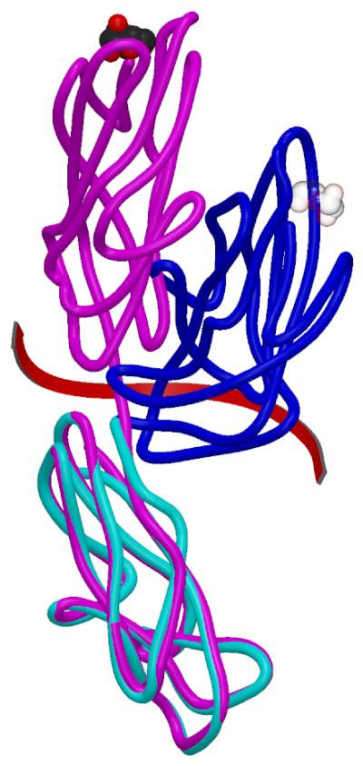
Superposition of the FimH subunit in the tip complex (blue (lectin domain) and cyan (pilin domain)) and FimH/FimC (PDB entry 1KLF) (magenta). The mannose binding site is denoted in CPK mode and is transparent in the un-liganded pilin domain found in this structure. The screw operation relating the lectin domains is shown by the red arrow. When the two lectin domains are superposed using Coot (Emsley and Cowtan, 2004) and its SSM algorithm (Krissinel and Henrick, 2004), the rmsd for 116 Cα atoms is 1.18 Å.
The FimH lectin domains in these complexes retain the overall topology seen in earlier crystal structures, but there are extensive shifts of the β-strands and loops. These changes constitute an allosteric regulation of the lectin domain by the pilin domain, as described elsewhere (Le Trong et al., 2010). The changes were not observed in previous FimH/FimC structures, suggesting that complexation with FimC interferes with the allosteric regulation. This emphasizes the need to understand the effect of chaperone binding on fimbrial subunit structures.
Structural Differences in FimH Associated with Replacement of the Chaperone
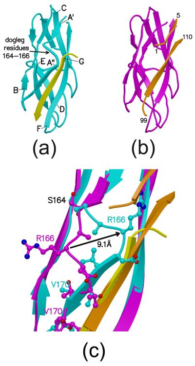
Crystallographic or NMR structures are available for FimH and FimF in complex with FimC. In previously determined crystal structures of FimH/FimC (Choudhury et al., 1999; Hung et al., 2002) and FimF/FimC (Eidam et al., 2008), residues 101 to 107 of the chaperone occupy the groove between the first (A) and last (F) β-strands of the FimH pilin domain or the FimF subunit (Figures 3a and 4).
Figure 3.
FimH pilin domains. (a). FimH pilin domain (cyan) bound to the donor strand (yellow) from FimG (this structure). Letters denoting the β-strands point to the N-terminus of each strand. The G strand for the domain is the donor strand from FimG. (b). FimH/FimC pilin domain from PDB entry 1KLF in magenta. Portions of FimC in orange. Residue numbers provided for portions of FimC. (c). Superposition of FimH and FimH/FimC pilin domains (same coloring scheme as in (a) and (b).) Amino acid side-chains near the dogleg are shown as balls and sticks while the polypeptide backbone is shown as a coil or β-strand. The black arrow indicates the change in structure for Arg166.
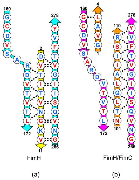
Figure 3 shows a comparison of the FimH pilin domain with the FimH/FimC structure from PDB entry 1KLF. Included in the figures are the donor strand from FimG found in the tip complex (strand G in Figure 3a) and the FimC β-strand filling the donor strand groove (Figure 3b). The major difference between FimH and FimH/FimC occurs between residues 164 and 173 where the polypeptide shifts around 10 Å to take on a new conformation in FimH (Figure 3c). This structural shift allows for more extensive interactions with the donor strand from FimG than with the chaperone protein. The differences between FimH and FimH/FimC are shown schematically in Figure 5.
Figure 5.
Schematic diagram showing the alignment of the polypeptide chains. (a) FimH (cyan) in complex with FimG donor strand (yellow). Main chain hydrogen bonds shown as dashed lines. Residues with side chains pointing towards the center of the domain shown in red. Residues pointing away from the center shown in blue. Residue numbers shown for ends of each polypeptide segment. (b) FimH (magenta) in complex with FimC (orange). Hydrogen bonds and side chain orientations as in (a).
Residues 161 to 164 of FimH superpose well with the same residues in FimH/FimC and form a β-strand (strand A′ in Figure 3a) that is hydrogen bonded to residues 184 to 187 in the second β-strand in the domain. In addition, residues 166 to 172 (strand A″) are hydrogen bonded to residues 4-8 of the donor strand from FimG. This contiguous piece of polypeptide chain (FimH, residues 161-172) interacts with one β-strand at one end and a second strand at the other end. In the FimH/FimC structure, residues V168, V170 and I172 face outward from the center of the domain and T169 and T171 point inward toward the hydrophobic core. The orientation of these residues flips in the native FimH structure when the A″ strand interacts with FimG. The FimG-bound conformation is more energetically favorable based on the hydrophobicity of buried versus exposed residues, so this conformational switch may contribute to the ability of FimG to displace FimC during pilogenesis.
To accommodate the two sets of hydrogen bonding interactions to different β-strands, the polypeptide bends between residues 164 and 166, introducing a ‘dogleg’ (Adman, 1985) to produce a crossover between the A′ and A″ β-strands. The chain zigzags so the backbone of residues 164-166 is approximately perpendicular to the backbone of the previous and following residues. The donor strand from FimG extends only two residues beyond the dogleg, and presumably that contributes to the stability of this arrangement of shifted β-strands.
FimG's donor strand runs parallel to the first β-strand in FimH's pilin domain (strand A″) and antiparallel to its last strand (strand F). The corresponding segment of FimC filling the donor strand groove in FimH/FimC is about the same length, runs antiparallel to the first FimH strand, and is shifted by a few residues towards the C-terminus of the FimH pilin domain. This was seen previously in the crystal structures of PapE (Sauer et al., 2002). Residues 164 to 173 of FimH/FimC do not form the dogleg structure because residues 1-4 of FimC block the area that would be occupied by several side-chains if FimH/FimC took on that conformation.
Donor Strand Interactions in FimG
FimG in the tip structure contains a dogleg in the polypeptide chain near residue 22. No structure of FimG complexed with FimC has yet been reported, but we expect it will follow the pattern seen for FimH where the chaperone restricts formation of the dogleg in the polypeptide tracing. The amino acid sequence of FimG in this region is similar to that of FimH (Cys16 and Val18 in FimG align with Cys161 and Val163 in the FimH pilin domain). The disulfide bridge involving the cysteine provides a structural restraint on this part of the polypeptide in each structure, and the valine is positioned to interact with FimC.
Different Structural Changes in FimF Upon Donor Strand Complementation
Figure 4 shows a superposition of FimF (chain F in this structure) and FimF/FimC (PDB entry 3BWU (Eidam et al., 2008)). The two β-sheets in the domain pack slightly differently in the two structures, much as described for Caf1/Caf1M (Zavialov et al., 2003). However, a more localized conformational change occurs when the polypeptide chain in the first strand shifts from an extended conformation in FimF/FimC to one making more hydrogen bonds with the donor strand (strand G) contributed by the second FimF (chain E).
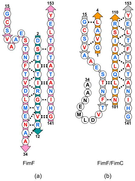
In addition to a dogleg appearing in the first β-strand of FimF, a short helix is found for residues 19-23 of FimF. This results in a change in register of the residues in FimF and FimF/FimC. The structures are aligned at residue 16, a cysteine involved in an intra-domain disulfide bridge, but after the helix and dogleg, residue 28 in FimF aligns with 24 in FimF/FimC, see Figure 6. The two structures are in register at residue 40. The additional residues added to the first β-strand of FimF come from the loop extending beyond the strand. There is a gap in the polypeptide model for FimF/FimC (residues 26-39) indicating that that part of the protein in the chaperone complex might be flexible and disordered.
Figure 6.
Schematic diagram showing the alignment of the polypeptide chains. (a) FimF (pink) in complex with FimF donor strand (teal). Main chain hydrogen bonds shown as dashed lines. Residues with side chains pointing towards the center of the domain shown in red. Residues pointing away from the center shown in blue. Residue numbers shown for ends of each polypeptide segment. (b) FimF (grey) in complexes with FimC (orange). Hydrogen bonds and side chain orientations as in (a).
These changes in FimF are not unique to the comparison of FimF and FimF/FimC described here. The changes are also seen when the comparison includes the solution structure of FimF complexed with its own donor strand (Gossert et al., 2008) and the FimF/FimC complex observed in a previous crystal structure (Eidam et al., 2008). This demonstrates that the structural change is not due to crystal packing interactions.
Association of Donor Strand Exchange and Inter-domain Interactions
The structures of the FimH pilin domain, FimG and FimF (chains F and E) are very similar and readily superposable (Figure 7), but that of the FimH lectin domain differs substantially in the twisting of the β-sandwich and the orientation and lengths of the inter-strand loops. In the FimH pilin domain, the donor strand groove extends beyond the N-terminus of the donor strand (Figure 3a) and provides space for interactions with residues 113-116 from the lectin domain, the insertion loop. Interactions between this loop from the lectin domain and the binding groove in the pilin domain contribute to the allosteric regulation of mannose binding (Le Trong et al., 2010). This loop is seen only at the interface between the FimH lectin and pilin domains, with no comparable structural feature at the FimH(pilin)-FimG and FimG-FimF interfaces.
In FimH/FimC, the N-terminal residues of FimC occupy part of the groove and prevent binding of the insertion loop, thus blocking a critical function of FimH. In the absence of FimC, the extension of the FimH groove is unoccupied. The dogleg does not close this part of the groove. In the FimH structure, as compared to FimH/FimC, the side-chain of residue Tyr278 bends out of the extended groove, and the dogleg places Arg166 in position to hydrogen bond with the insertion loop residues. This latter is likely to be significant, since a mutation in Arg166 is already known to affect FimH binding (Sokurenko et al., 1995). These observations emphasize the importance of understanding the conformational changes that occur upon replacement of FimC with the biologically relevant N-terminal donor strand. The conformational changes in the A′ and A″ strands of the FimH pilin domain accompanying DSE position Arg166 to interact with the insertion loop, and are thus also connected with the rearrangement of the lectin and pilin domains shown in Figure 2.
Specificity of Subunit Interactions
The major contribution to the binding of the chaperone and donor strands in the donor strand groove is the fit of specific amino acid side-chains into specific binding pockets. This has been addressed at a general level in earlier publications (Gossert et al., 2008). The structure of the tip complex described here permits a more detailed three-dimensional view of the binding partners and shows that the donor strand does not simply replace the chaperone in a set of pre-built binding pockets in the Fim proteins. Conformational changes of the A″ strand change the amino acid residues that interact with the donor strand. As seen in Figure 8 when the donor strand is bound, the A″ strand moves to interact tightly with it. This vise-like motion enhances the interacting surface and presumably the specificity and strength of binding. In the structure analyzed here (3JWN), there are three different combinations of native donor strands with native binding grooves, the FimG donor strand bound to the FimH pilin domain, the FimF donor strand bound to FimG, and the FimF (chain E) donor strand bound to FimF. Table 1 summarizes the inter-atomic distances between the donor strand residues and residues forming the groove that are shorter than the sum of the atoms' van der Waals radii. When the donor strand joins the β-sandwich it does so with side-chains from one side of the strand pointing into the interior of the domain and side-chains from the other side pointing outwards. This encourages the idea that binding, both in terms of strength and specificity, will be largely controlled by the interior side-chains located in specific binding pockets (Gossert et al., 2008). However there are a large number of van der Waals violations involving the donor strand residues pointing towards the outside of the protein (Table 1). These interatomic interactions will also contribute to the specificity and stability of binding of the donor strands in their respective grooves. It should also be noted that the differences between the binding pockets for the chaperone strands and the native donor strands will contribute to the specificity of binding for the Fim subunits.
Table 1.
Van der Waals Contact Statistics for Donor Strands and Grooves donor strands
| FimG residues 1-12 |
FimF residues 1-12 |
FimF(chain E) residues 1-12 |
|||||||
|---|---|---|---|---|---|---|---|---|---|
| all a residues |
inner residues |
outer residues |
all residues |
inner residues |
outer residues |
all residues |
inner residues |
outer residues |
|
| # vdw overlap b |
25 | 13 | 12 | 30 | 15 | 15 | 23 | 10 | 13 |
| max. overlap Ǻ |
0.45 | 0.43 | 0.45 | 0.49 | 0.48 | 0.39 | 0.40 | 0.33 | 0.40 |
Note:
“Inner” and “outer” refer to the orientation of the side-chains on the donor strand. Inner residues have their side-chains pointing towards the center of the domain while outer residues have them pointing towards the solvent. “All” refers to all residues of the donor strand.
The number of van der Waals overlaps is the number of contacts between atoms of the donor strand and atoms from the groove that are less than the sum of the van der Waals radii of the interacting atoms. The maximum overlap is the largest for the set of atoms involved in the strand and groove interaction.
The presence of two FimF molecules in the complex raises questions about the control and regulation of fimbrial assembly. This is at least the third time a pilus subunit has been seen to dimerize but not to form longer polymers. The other cases involved polymerization-defective engineered variants of the major subunits PapA (Verger et al., 2007) and Caf1 (Zavialov et al., 2003). If the natural tip contains multiple copies of FimF, some means must exist for limiting the number of FimF molecules in the assembly. In this structure, the second copy of FimF is bound to FimC, so we have no structural model of a complex containing two FimF molecules bound to native donor strands. Perhaps binding of FimF to FimF alters the second binding site and limits the binding of subsequent copies of FimF, but it is also possible that interactions with the usher (FimD) regulate the incorporation of FimF into the fimbriae. As noted above, interactions of the subunits with FimC are not limited to the donor strand groove, and the N-terminus of FimC is positioned to block formation of the dogleg structure in the fimbrial subunits. Removal and replacement of these interactions will necessarily be part of the assembly mechanism.
Previous comparisons of the amino acid sequences of the donor strands, including that of FimA (the major fimbrial subunit), indicate that special structural changes will accompany binding of the FimA donor strand to FimF. The FimA donor strand is longer than those of the other subunits, and if the current sequence alignments (Gossert et al., 2008) are correct, it will extend further along the binding groove towards the end of the F strand. This might be stabilized by a further rearrangement of FimF's A″ strand or by a register shift of FimA's donor strand to change the residues bound to the binding pockets in FimF. Another aspect of the current sequence alignment of FimA's donor strand that will have structural ramifications is the insertion of a large phenylalanine residue (F177) into the binding groove where isoleucine or valine in FimF and FimG bind. Insertion of such a large side-chain would likely be accompanied by substantial structural rearrangements best characterized by experimental determinations of the molecular structures involved.
Discussion
The pentameric complex described here permits an assessment of structural changes in the Fim proteins that occur upon DSE, but other bacterial pilus subunits respond differently to the change in environment when the chaperone is replaced by the donor strand. For example, crystal structures of PapE have been determined for the protein in complex with its chaperone, PapD (Sauer et al., 2002) (PDB identifier 1N0L), and in complex with the donor strand from PapK (Sauer et al., 2002) (PDB identifier 1N12). There is no significant conformational change in the first β-strand connected with switching from chaperone to donor strand binding for this protein.
A second example is provided by the crystal structure of PapA/PapD (Verger et al., 2007) (PDB identifier 2UY6). The asymmetric unit of this crystal form contains two PapA molecules and one PapD chaperone. One PapA binds to the chaperone while the second is bound to the donor strand from the first. The two PapA molecules have nearly identical dogleg conformations in their first β-strands so they can bind both the chaperone and the donor strands in similar ways. However, the doglegs are positioned slightly differently along the polypeptide chain. This results in an amino acid sequence registration difference for the two structures. The structures are in register at residue 22 where Cys22 makes a disulfide link with Cys61. The structures are also in register at residue 31, so the structural differences associated with replacement of the chaperone with the donor strand are localized to the polypeptide between residues 22 and 30.
A third example concerns the F1 capsular antigen, Caf1, and its chaperone. Two crystal structures (Zavialov et al., 2003; Zavialov et al., 2005) (PDB identifiers 1P5U and 1Z9S) are like the PapA structure in that they contain two copies of Caf1 and one of Caf1M chaperone, so they provide views of the pilus subunit, both complexed with the chaperone and with the native donor strand. There is a general collapse of the Caf1 fold after DSE and this is believed to support formation of the Caf1 fibers, but there are no large conformational differences in the first β-strand in the two structures.
No general pattern of structural changes is associated with replacement of the chaperone protein with native donor strands. Each example described here, including the FimH and FimF cases, is different in the way the A″ strand accommodates and optimizes its interactions with the donor strand. The structures of some of the molecules (Caf1, PapE) differ little between their complexes with the chaperone and their complexes with native or native-like donor strands. The A″ strands of others (FimH, FimF, PapA) move to interact with the native donor strands. They do this by introducing a dogleg structure and/or by shifting the registration of the polypeptide chain. The variety of structural responses complicates our understanding of the assembly of the biologically important assemblages, but it also provides an element of specificity that might be advantageous in the design of agents aimed at disrupting subunit assembly.
The pentameric complex analyzed here is the largest fimbrial tip structure seen to date. Donor strand exchange accounts for the important inter-subunit interactions stabilizing the extended structure. Comparison with previous structures of FimC complexes shows that significant conformational changes occur when the native donor strands are incorporated into the domains. A dogleg structure is taken up by the first β-strand to optimize the interactions with the native donor strand. This structural rearrangement is blocked in the FimC complexes of the proteins. The change in conformation between the complemented and exchanged conformations means that the residues forming the binding pockets for the donor strand differ from those binding the chaperone strand (see Figures 5 and 6). This may be necessary to allow multiple subunits to bind the same chaperone but then to differ in specificity with respect to donor strands. For example, FimH flips a β-strand (residues 168 to 172) to accommodate FimC, but the favoured position is to switch the hydrophobic residues outward, which may provide specificity for the FimG donor strand. Finally, the structural changes occurring upon DSE may be critical for the functioning of the assembled fimbriae, as indicated by the changes in the groove extension of the FimH pilin domain, which binds to and regulates the interactions between the FimH lectin and pilin domains.
Acknowledgements
We thank Eric Larson and Gianluca Interlandi, for helpful discussions. This work has been supported by NIH grant RO1 AI 50940. B.K. was supported partially by NIH training grant T32 GM008268. We thank the Advanced Light Source for beamtime. The Advanced Light Source is supported by the Director, Office of Science Office of Basic Energy Sciences, of the U.S. Department of Energy under Contract No. DEAC02-05CH11231.
Abbreviations
- DSC
donor strand complementation
- DSE
donor strand exchange
- rmsd
root mean square difference
Footnotes
Publisher's Disclaimer: This is a PDF file of an unedited manuscript that has been accepted for publication. As a service to our customers we are providing this early version of the manuscript. The manuscript will undergo copyediting, typesetting, and review of the resulting proof before it is published in its final citable form. Please note that during the production process errors may be discovered which could affect the content, and all legal disclaimers that apply to the journal pertain.
References
- Adman ET. Structure and Function of Small Blue Copper Proteins. Topics in Molecular and Structural Biology. 1985;6:1–42. [Google Scholar]
- Barnhart MM, Pinkner JS, Soto GE, Sauer FG, Langermann S, Waksman G, Frieden C, Hultgren SJ. PapD-like chaperones provide the missing information for folding of pilin proteins. Proc Natl Acad Sci U S A. 2000;97:7709–7714. doi: 10.1073/pnas.130183897. [DOI] [PMC free article] [PubMed] [Google Scholar]
- Brünger AT. Assessment of phase accuracy by cross validation: the free R value. Methods and applications. Acta Cryst. 1993;D49:24–36. doi: 10.1107/S0907444992007352. [DOI] [PubMed] [Google Scholar]
- Choudhury D, Thompson A, Stojanoff V, Langermann S, Pinkner J, Hultgren SJ, Knight SD. X-ray Structure of the FimC-FimH Chaperone-Adhesin Complex from Uropathogenic Escherichia coli. Science. 1999;285:1061–1066. doi: 10.1126/science.285.5430.1061. [DOI] [PubMed] [Google Scholar]
- Collaborative Computational Project, N The CCP4 Suite: Programs for Protein Crystallography. Acta Cryst. 1994;D50:760–763. doi: 10.1107/S0907444994003112. [DOI] [PubMed] [Google Scholar]
- Eidam O, Dworkowski FSN, Glockshuber R, Grütter MG, Capitani G. Crystal structure of the ternary FimC-FimFt-FimDN complex indicates conserved pilus chaperone-subunit complex recognition by the usher FimD. FEBS Lett. 2008;582:651–655. doi: 10.1016/j.febslet.2008.01.030. [DOI] [PubMed] [Google Scholar]
- Emsley P, Cowtan K. Coot: model-building tools for molecular graphics. Acta Cryst. 2004;D60:2126–2132. doi: 10.1107/S0907444904019158. [DOI] [PubMed] [Google Scholar]
- Fronzes R, Remaut H, Waksman G. Architectures and biogenesis of nonflagellar protein appendages in Gram-negative bacteria. Embo Journal. 2008;27:2271–2280. doi: 10.1038/emboj.2008.155. [DOI] [PMC free article] [PubMed] [Google Scholar]
- Gossert AD, Bettendorff P, Puorger C, Vetsch M, Herrmann T, Glockshuber R, Wüthrich K. NMR Structure of the Escherichia coli Type 1 Pilus Subunit FimF and Its Interactions with Other Pilus Subunits. J. Mol. Biol. 2008;375:752–763. doi: 10.1016/j.jmb.2007.10.059. [DOI] [PubMed] [Google Scholar]
- Hung C-S, Bouckaert J, Hung D, Pinkner J, Widberg C, DeFusco A, Auguste CG, Strouse R, Langermann S, Waksman G, Hultgren SJ. Structural basis of tropism of Escherichia coli to the bladder during urinary tract infection. Molecular Microbiology. 2002;44:903–915. doi: 10.1046/j.1365-2958.2002.02915.x. [DOI] [PubMed] [Google Scholar]
- Kissinger CR, Gehlhaar DK, Fogel DB. Rapid automated molecular replacement by evolutionary search. Acta Cryst. 1999;D55:484–491. doi: 10.1107/s0907444998012517. [DOI] [PubMed] [Google Scholar]
- Kraulis PJ. Molscript - a program to produce both detailed and schematic plots of protein structures. J. Appl. Crystallogr. 1991;24:946–950. [Google Scholar]
- Krissinel E, Henrick K. Secondary-structure matching (SSM), a new tool for fast protein structure alignment in three dimensions. Acta Cryst. 2004;D60:2256–2268. doi: 10.1107/S0907444904026460. [DOI] [PubMed] [Google Scholar]
- Le Trong I, Aprikian P, Kidd BA, Forero-Shelton M, Tchesnokova V, Rajagopal P, Rodriguez V, Interlandi G, Klevit R, Vogel V, Stenkamp RE, Sokurenko EV, Thomas WE. Mechanical activation of the bacterial adhesive protein FimH involves allostery in a β-sandwich. Cell. 2010 in press. [Google Scholar]
- McCoy AJ, Grosse-Kunstleve RW, Adams PD, Winn MD, Storoni LC, Read RJ. Phaser crystallographic software. J. Appl. Cryst. 2007;40:658–674. doi: 10.1107/S0021889807021206. [DOI] [PMC free article] [PubMed] [Google Scholar]
- McRee DE. XtalView Xfit - A versatile program for manipulating atomic coordinates and electron density. J. Structural Biology. 1999;125:156–165. doi: 10.1006/jsbi.1999.4094. [DOI] [PubMed] [Google Scholar]
- Merritt EA, Bacon DJ. Raster3D: Photorealistic molecular graphics. Meth. Enzym. 1997;277:505–524. doi: 10.1016/s0076-6879(97)77028-9. [DOI] [PubMed] [Google Scholar]
- Murshudov GN, Vagin AA, Dodson EJ. Refinement of macromolecular structures by the maximum-likelihood method. Acta Cryst. 1997;D53:240–255. doi: 10.1107/S0907444996012255. [DOI] [PubMed] [Google Scholar]
- Otwinowski Z, Minor W. Processing of X-ray diffraction data collected in oscillation mode. Meth. Enzym. 1997;276:307–326. doi: 10.1016/S0076-6879(97)76066-X. [DOI] [PubMed] [Google Scholar]
- Puorger C, Eidam O, Capitani G, Erilov D, Grütter MG, Glockshuber R. Infinite Kinetic Stabiity against Dissociation of Supramolecular Protein Complexes through Donor Strand Complementation. Structure. 2008;16:631–642. doi: 10.1016/j.str.2008.01.013. [DOI] [PubMed] [Google Scholar]
- Read RJ. Improved Fourier Coefficients for Maps Using Phases from Partial Structures with Errors. Acta Cryst. 1986;A42:140–149. [Google Scholar]
- Sauer FG, Pinkner JS, Waksman G, Hultgren SJ. Chaperone Priming of Pilus Subunits Facilitates a Topological Transition that Drives Fiber Formation. Cell. 2002;111:543–551. doi: 10.1016/s0092-8674(02)01050-4. [DOI] [PubMed] [Google Scholar]
- Sokurenko EV, Courtney HS, Maslow J, Sitonen A, Hasty DL. Quantitative differences in adhesiveness of type 1 fimbriated Escherichia coli due to structural differences in fimH genes. J. Bacteriol. 1995;177:3680–3686. doi: 10.1128/jb.177.13.3680-3686.1995. [DOI] [PMC free article] [PubMed] [Google Scholar]
- Vagin AA, Teplyakov A. MOLREP: an automated program for molecular replacement. J. Appl. Crystallogr. 1997;30:1022–1025. [Google Scholar]
- Verger D, Bullitt E, Hultgren SJ, Waksman G. Crystal Structure of the P Pilus Rod Subunit PapA. PLos Pathog. 2007:3. doi: 10.1371/journal.ppat.0030073. [DOI] [PMC free article] [PubMed] [Google Scholar]
- Zavialov AV, Berglund J, Pudney AF, Fooks LJ, Ibrahim TM, MacIntyre S, Knight SD. Structure and Biogenesis of the Capsular F1 Antigen from Yersinia pestis: Preserved Folding Energy Drives Fiber Formation. Cell. 2003;113:587–596. doi: 10.1016/s0092-8674(03)00351-9. [DOI] [PubMed] [Google Scholar]
- Zavialov AV, Tischenko VM, Fooks LJ, Brandsdal BO, Ǻqvist J, Zav'yalov VP, MacIntyre S, Knight SD. Resolving the energy paradox of chaperone/usher-mediated fibre assembly. Biochem. J. 2005;389:685–694. doi: 10.1042/BJ20050426. [DOI] [PMC free article] [PubMed] [Google Scholar]


