Abstract
A layer-by-layer technique has been developed to synthesize FeOOH–Au hybrid nanorods that can be transformed into Fe2O3–Au and Fe3O4–Au hybrid nanorods via controllable annealing process. The homogenous deposition of Au nanoparticles onto the surface of FeOOH nanorods can be attributed to the strong electrostatic attraction between metal ions and polyelectrolyte-modified FeOOH nanorods. The annealing atmosphere controls the phase transformation from FeOOH–Au to Fe3O4–Au and α-Fe2O3–Au. Moreover, the magnetic and optical properties of as-synthesized Fe2O3–Au and Fe3O4–Au hybrid nanorods have been investigated.
Keywords: Layer-by-layer, Hybrid nanomaterials, Iron oxide, Magnetic properties
Introduction
Hybrid nanomaterials consisting of two or more different nanoscale functionalities have attracted much attention due to their novel combined properties and technological applications [1,2]. Among them, iron oxide–Au (Fe3O4–Au, α/γ-Fe2O3–Au) nanocomposites are of great importance for their combined optical and magnetic properties and potential applications in the fields of biotechnologies and catalysts [3-8]. Up to now, many methods have been developed to synthesize various Fe3O4–Au and α/γ-Fe2O3–Au nanocomposites [9-19]. For example, Yu et al. [10] reported the synthesis of dumbbell-like Fe3O4–Au nanoparticles using decomposition of Fe(CO)5 on the surface of the Au nanoparticles followed by oxidation in 1-octadecene. Fe3O4–Au core–shell nanoparticles could be prepared with room-temperature coating of Au on the surface of Fe3O4 nanoparticles by reducing HAuCl4 in a chloroform solution of oleylamine [11]. Wu et al. [12] prepared magnetic Fe3O4–Au nanoparticles by the controlling a combination of chemically tunable chelating layer modifications for magnetic core and further deposition of Au on the amine-functionalized Fe3O4 surface. Bao et al. [18] reported the synthesis of γ-Fe2O3–Au nanoparticles with different Au shell thickness by reducing HAuCl4 on the surface of γ-Fe2O3 nanoparticles. Moreover, the synthesis and transformation of 1D nanostructures and their hybrids are of particular interest due to their immense applications [20-22]. However, to the best of our knowledge, there is no report for the controllable synthesis of Fe2O3–Au and Fe3O4–Au hybrid 1D nanostructures.
Layer-by-layer technique is based on the electrostatic attraction between charge species, and it has been widely used to synthesize nanocomposites [23-28]. More recently, this technique has been realized to prepare hybrid 1D nanostructures [29-36]. Herein, we use layer-by-layer technique to synthesize uniform FeOOH–Au hybrid nanorods that can be controllably transformed into Fe2O3–Au and Fe3O4–Au hybrid nanorods. The magnetic and optical properties of as-synthesized Fe2O3–Au and Fe3O4–Au hybrid nanorods have been investigated.
Experimental Section
Synthesis
Poly (sodium 4-styrenesulfonate) (PSS) and Poly (allylamine hydrochloride) (PAH) were purchased from Alfa Aesar Co. Ltd. All the chemicals were of analytical grade without further purification. First, FeOOH nanorods were prepared by a hydrothermal route described elsewhere [37]. Second, the pristine FeOOH nanorods were modified by polyelectrolyte (PAH/PSS/PAH) in sequence via layer-by-layer assembly. Briefly, 10 mg FeOOH nanorods was sonicated for 1 h in 50 ml 1 M NaCl solution, and 80 mg PAH was added and stirred for 0.5 h. Subsequently, the excess PAH was removed by six repeated centrifugation/wash cycles. Similarly, the PSS and PAH layers were then coated on the surface of the PAH-modified FeOOH nanorods to obtain the PAH/PSS/PAH-modified FeOOH nanorods. Third, FeOOH–Au nanorods were fabricated by chemical reaction using HAuCl4, trisodium citrate, and NaBH4 as reactants on PAH/PSS/PAH modified FeOOH nanorod templates. The resulting solid products were centrifuged, washed with distilled water and ethanol to remove the ions possibly remaining in the final products, and finally dried at 80°C in air.
For the synthesis of α-Fe2O3–Au nanorods, the as-prepared FeOOH–Au nanorods were heated to 500°C for 3 h in air. While for the synthesis of Fe3O4–Au nanorods, the as-prepared FeOOH–Au nanorods were heated to 400°C for 3 h under H2/Ar (10% H2) atmosphere.
Characterization
The obtained samples were characterized by X-ray powder diffraction (XRD) using a Rigaku D/max-ga X-ray diffractometer with graphite monochromatized Cu Kα radiation (γ = 1.54178 Å). The morphology and structure of the samples were examined by transmission electron microscopy (TEM, JEM-200 CX, 160 kV), field emission scanning electron microscopy (FESEM, Hitachi S-4800) and high-resolution transmission electron microscopy (HRTEM, JEOL JEM-2010). The infrared (IR) spectra were measured with a Nicolet Nexus FTIR 670 spectrophotometer. Magnetization measurements were carried out using a physical property measurement system (PPMS-9, Quantum Design). The optical absorption of the products was examined by a Perkin–Elmer Lambda 20 UV/vis Spectrometer. BET surface area and pore volume were tested using Beckman coulter omnisorp 100cx.
Results and Discussion
Figure 1a shows the XRD pattern of as-synthesized FeOOH–Au hybrid nanorods via layer-by-layer assembly. It can be seen that all diffraction peaks can be assigned to tetragonal FeOOH (JCPDS no. 75-1594) and Au (JCPDS no. 65-2870), indicating the synthesis of pure FeOOH–Au hybrid nanorods. Moreover, the XRD peaks were considerably broad, which implied that Au existed in the form of small size. Figure 1b shows the SEM image of as-synthesized FeOOH–Au hybrid nanorods. As observed, the surface of hybrid nanorods turn into rough compared to pure FeOOH nanorods [37], which confirm the deposition of Au nanoparticles. Moreover, no isolated Au nanoparticles can be detected, indicating that all Au nanoparticles have been deposited onto FeOOH nanorods (Fig. 1c). Figure 1d shows the TEM image of an individual FeOOH–Au nanorod. It can be clearly observed that Au nanoparticles with diameters of about 5 nm have been homogenously deposited onto the surface of FeOOH nanorod. IR, BET surface area and pore volume analysis were examined to confirm the successful surface modification of PAH/PSS/PAH by the layer-by-layer technique. As shown in Fig. 2a, 2b, the additional peaks at 1008, 1035 and 1180 cm−1 after layer-by-layer assembly can be attributed to benzyl ring in PSS, SO3− symmetric stretching, and SO3− asymmetric stretching, respectively, which confirms the successful surface modification of polyelectrolyte [38]. Figure 2 shows nitrogen adsorption and desorption isotherms of FeOOH nanorods (c) before layer-by-lay assembly and (e) after layer-by-lay assembly at 77 K with corresponding pore-size distribution calculated by BJH method from desorption branch (d) and (f). Before layer-by-lay assembly, the FeOOH nanorods have a BET surface area of 13.8 m2 g−1 with an average Barretl-Joyner-Halenda (BJH) pore diameter of 23.1 nm. After layer-by-lay assembly, the values are 11.9 m2 g−1, 37.7 nm, respectively. From the result of BET analysis, we can find that the BET surface area decrease after the layer-by-lay assembly. The possible reason for this phenomenon is that the polyelectrolyte deposited on the surface of FeOOH nanorods makes the surface smoother and leads to the reduction of the BET surface area. In order to confirm the effect of layer-by-layer process on the formation of the uniform FeOOH–Au hybrid nanorods, comparative experiments have been done. In the absence of polyelectrolyte, only some –OH or –COOH functional groups on FeOOH could act as anchoring sites for Au nanoparticles growth, which resulted in the sparse deposition of inhomogenous Au nanoparticles on FeOOH nanorods (Fig. 3a) [32]. When FeOOH nanorods were modified by two-layer polyelectrolyte (PAH/PSS), Au nanoparticles accumulated and were rarely deposited onto the surface of FeOOH nanorods. The above-mentioned analysis indicates that the strong electrostatic attraction between AuCl4− and polyelectrolyte-modified FeOOH nanorods plays the most important role in the uniform deposition of Au nanoparticles.
Figure 1.
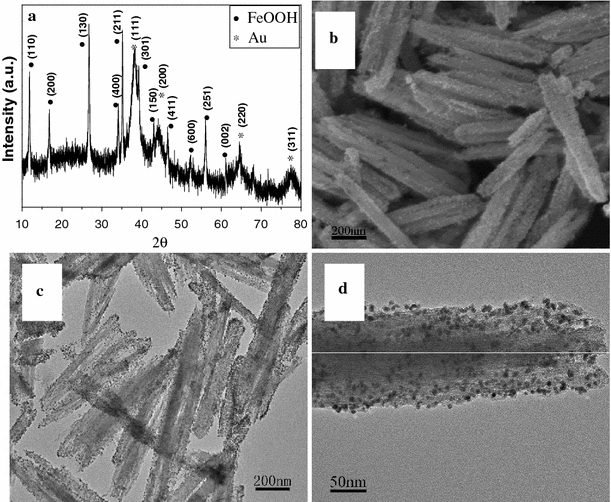
Morphological and structural characterizations of FeOOH–Au hybrid nanorods synthesized via layer-by-layer assembly: a XRD pattern; b SEM image; c, d TEM image
Figure 2.
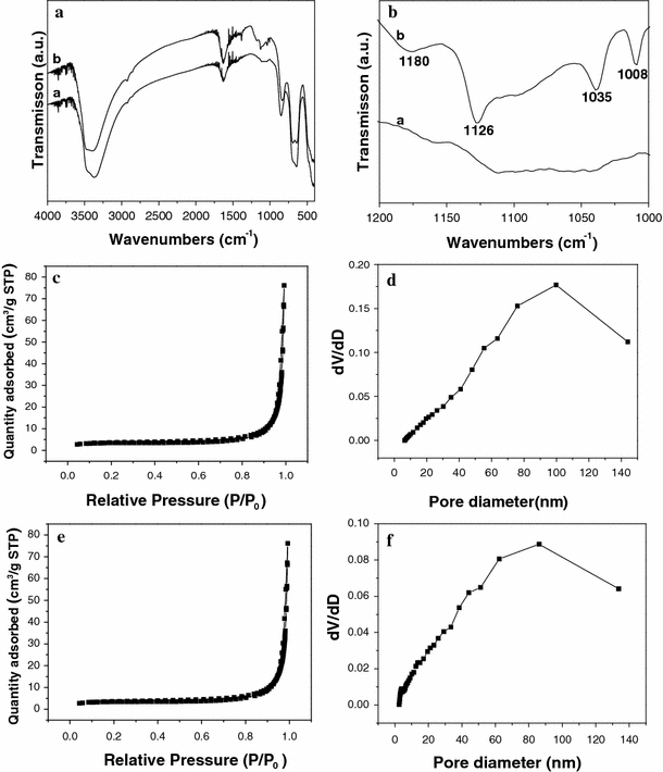
a, b Infrared spectra of FeOOH nanorods (curve a) before layer-by-lay assembly and (curve b) after layer-by-lay assembly; nitrogen adsorption and desorption isotherms of FeOOH nanorods c before layer-by-lay assembly and e after layer-by-lay assembly at 77 K with corresponding pore-size distribution calculated by BJH method from desorption branch (d) and (f)
Figure 3.
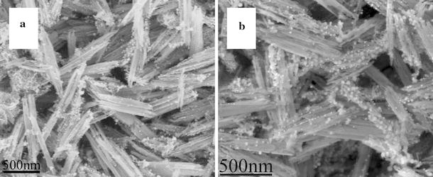
SEM images of FeOOH–Au hybrid nanorods synthesized without layer-by-layer process (a) and with two-layer (PAH/PSS) assembly (b)
Figure 4 shows the morphological and structural characterizations of the products synthesized by annealing of FeOOH–Au hybrid nanorods under air atmosphere at 500°C. It can be seen that all diffraction peaks can be assigned to α-Fe2O3 (JCPDS no. 33-0664) and Au (Fig. 4a). No other diffraction peaks relating to FeOOH or other iron oxides are observed. The morphology of α-Fe2O3–Au hybrid nanorods seems changed little compared to FeOOH–Au hybrid nanorods. Au nanoparticles have been homogenously deposited onto the surface of α-Fe2O3 nanorods (Fig. 4b). However, the diameter of Au nanoparticles in α-Fe2O3–Au hybrid nanorods is larger than that in FeOOH–Au hybrid nanorods because of Ostwald ripening of Au nanoparticles. The particle size increases with the annealing temperature. Similar result has been discovered in the Au–ZnO nanohybrids [39]. Figure 4d shows the HRTEM image of an individual α-Fe2O3–Au nanorod. There are two lattice fringes with lattice spacings of 0.235 and 0.252 nm corresponding to the Au {111} and α-Fe2O3 {110} planes from different grains, respectively, which further confirm the synthesis of α-Fe2O3–Au hybrid nanorods. When FeOOH–Au hybrid nanorods were annealing under H2/Ar (10% H2) atmosphere at 400°C, Fe3O4–Au hybrid nanorods can be obtained. Figure 5a shows the XRD pattern of as-synthesized products, which confirm the synthesis of pure Fe3O4 (JCPDS no. 19-0629)–Au nanocomposites. Figure 5b, 5c shows the SEM and TEM image of Fe3O4–Au hybrid nanorods. It can be seen that Au nanoparticles have been homogenously deposited onto the surface of Fe3O4 nanorods, which is similar to α-Fe2O3–Au hybrid nanorods. However, the diameter of Au nanoparticles in Fe3O4–Au hybrid nanorods is smaller than that in α-Fe2O3–Au hybrid nanorods due to the relatively low annealing temperature (400°C). Figure 5d shows the HRTEM image of an individual Fe3O4–Au nanorod. It can be seen that there are two lattice fringes with lattice spacings of 0.235 and 0.296 nm corresponding to the Au {111} and Fe3O4 {220} planes from different grains, respectively, which further confirm the synthesis of Fe3O4–Au hybrid nanorods. IR analysis was employed to further confirm the synthesis of α-Fe2O3–Au and Fe3O4–Au hybrid nanorods (Fig. 6). It can be seen that there is only one peak at 570 cm−1 for Fe3O4, while α-Fe2O3 shows two or three peaks, which is related to its structure and size. Moreover, γ-Fe2O3 also exhibit three peaks between 500 and 700 cm−1, which is different from Fe3O4[40,41]. The IR analysis combined with TEM images and XRD pattern can confirm the synthesis of α-Fe2O3–Au and Fe3O4–Au hybrid nanorods.
Figure 4.
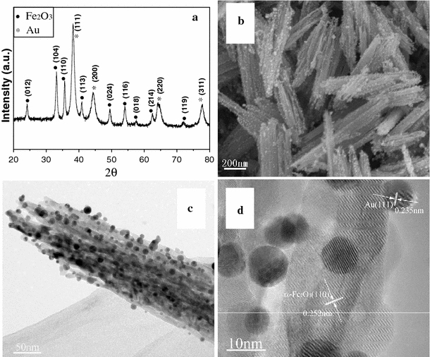
Morphological and structural characterizations of Fe2O3–Au hybrid nanorods synthesized by annealing of FeOOH–Au hybrid nanorods under air atmosphere: a XRD pattern; b SEM image; c TEM image; d HRTEM image
Figure 5.
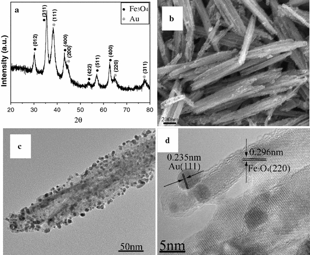
Morphological and structural characterizations of Fe3O4–Au hybrid nanorods synthesized by annealing of FeOOH–Au hybrid nanorods under Ar atmosphere: a XRD pattern; b SEM image; c TEM image; d HRTEM image
Figure 6.
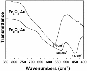
Infrared spectra of Fe2O3–Au and Fe3O4–Au hybrid nanorods
Fe3O4–Au and α-Fe2O3–Au hybrid nanorods show the combined magnetic and optical properties, which originate from iron oxide nanorods and Au nanoparticles, respectively. Figure 7 shows the room-temperature magnetization curves of Fe3O4–Au and α-Fe2O3–Au hybrid nanorods. It can be seen that Fe3O4–Au hybrid nanorods exhibit a typical ferromagnetic behavior, with a saturation magnetization, Ms = 29.8 emu g−1; remnant magnetization, Mr = 1.7 emu g−1; and coercive field, Hc = 50.1 Oe. The saturation magnetization of Fe3O4–Au hybrid nanorods is lower than that of bulk Fe3O4 (92 emu g−1) [42] due to the existence of non-magnetic Au; however, it is enough for biology and medicine application [3-6]. In contrast, α-Fe2O3–Au shows almost no magnetic property, which is similar to bulk α-Fe2O3. Therefore, Fe3O4–Au hybrid nanorods can be applied in biotechnologies [3-6], while α-Fe2O3–Au hybrid nanorods are more suitable for application in catalysts [7,43]. Figure 8 shows the room-temperature UV–vis spectra of Fe3O4–Au and α-Fe2O3–Au hybrid nanorods dispersed in ethanol. It is known that for Au nanoparticles with sizes ranging from 5 to 20 nm in diameter, the electrons are trapped in the small Au metal box and show a characteristic collective oscillation frequency of plasmon resonance, giving rise to the plasmon resonance band at around 520 nm [44]. The exact absorption varies with nanoparticles morphology and particle surface coating. Herein, compared to pure Fe3O4 and α-Fe2O3 nanorods, both Fe3O4–Au and α-Fe2O3–Au hybrid nanorods show a broad peak located at about 525 nm, which is similar to previous reports [10-12]. Deposition of Au nanoparticles onto the surface of Fe3O4 and α-Fe2O3 nanorods results in the broadening of the peak [16].
Figure 7.
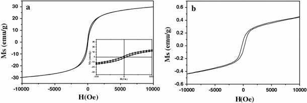
Room-temperature magnetization curves of Fe3O4–Au (a) and Fe2O3–Au (b) hybrid nanorods
Figure 8.
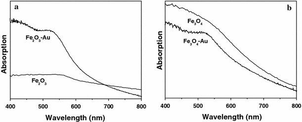
Room-temperature UV–vis spectra of Fe2O3–Au (a) and Fe3O4–Au (b) hybrid nanorods
Conclusions
FeOOH–Au hybrid nanorods have been synthesized via layer-by-layer assembly, which can be transformed into α-Fe2O3–Au and Fe3O4–Au hybrid nanorods by controllable annealing process. The strong electrostatic attraction between AuCl4− and polyelectrolyte-modified FeOOH nanorods plays the most important role in the uniform deposition of Au nanoparticles. The annealing atmosphere determines the phase transformation from FeOOH–Au to α-Fe2O3–Au and Fe3O4–Au. The as-synthesized Fe3O4–Au hybrid nanorods show the high saturation magnetizations, and α-Fe2O3–Au hybrid nanorods show the low saturation magnetizations, respectively. The UV–vis analysis indicates that both Fe3O4–Au and α-Fe2O3–Au hybrid nanorods show a broad peak located at about 525 nm. It is believed that the as-synthesized Fe3O4–Au and α-Fe2O3–Au hybrid nanorods can be applied in biotechnologies and catalysts, respectively.
Acknowledgments
The authors thank the Doctoral Science Foundation of Zhejiang Sci-Tech University (no. 0803611-Y) and National Natural Science Foundation of China (no. 50976106) for financial support.
Open Access
This article is distributed under the terms of the Creative Commons Attribution Noncommercial License which permits any noncommercial use, distribution, and reproduction in any medium, provided the original author(s) and source are credited.
References
- Mieszawska AJ, Jalilian R, Sumanasekera GU, Zamborini FP. Small. 2007. p. 722. COI number [1:CAS:528:DC%2BD2sXls1Wqtb8%3D] [DOI] [PubMed]
- Sanchez C, Julian B, Belleville P, Popall M. J. 2005. p. 3559. COI number [1:CAS:528:DC%2BD2MXpsFeitrY%3D] [DOI]
- Bao J, Chen W, Liu TT, Zhu YL, Jin PY, Wang LY, Liu JF, Wei YG, Li YD. ACS Nano. 2007. p. 293. COI number [1:CAS:528:DC%2BD2sXht1CmtrbN] [DOI] [PubMed]
- Zhao XL, Cai YQ, Wang T, Shi YL, Jiang GB. Anal. 2008. p. 9091. COI number [1:CAS:528:DC%2BD1cXhtlWqtbrL] [DOI] [PubMed]
- Xu CJ, Wang BD, Sun SH. J. 2009. p. 4216. COI number [1:CAS:528:DC%2BD1MXjtFKgs78%3D] [DOI] [PMC free article] [PubMed]
- Xie HY, Zhen R, Wang B, Feng Y, Chen P, Hao J. J. Phy. Chem. C. 2010. p. 4825. COI number [1:CAS:528:DC%2BC3cXisFGmtro%3D] [DOI]
- Andreeva D, Idakiev V, Tabakova T, Andreev A. J. 1996. p. 354. COI number [1:CAS:528:DyaK28XmsVGhsA%3D%3D] [DOI]
- Lee YM, Garcia MA, Huls NAF, Sun SH. Angew. 2010. p. 1271. [DOI] [PubMed]
- Wang LY, Luo J, Fan Q, Suzuki M, Suzuki TS, Engelhard MH, Lin YH, Kim N, Wang JQ, Zhong CJ. J. Phys. Chem. B. 2005. p. 21593. COI number [1:CAS:528:DC%2BD2MXhtFCmtb%2FL] [DOI] [PubMed]
- Yu H, Chen M, Rice PM, Wang SX, White RL, Sun SH. Nano Lett. 2005. p. 379. COI number [1:CAS:528:DC%2BD2MXkvFWisA%3D%3D]; Bibcode number [2005NanoL...5..379Y] [DOI] [PubMed]
- Xu ZC, Hou YL, Sun SH. J. 2007. p. 8698. COI number [1:CAS:528:DC%2BD2sXmslyqsrc%3D] [DOI] [PubMed]
- Wu W, He QG, Chen H, Tang JX, Nie LB. Nanotechnology. 2007. p. 145609. Bibcode number [2007Nanot..18n5609W] [DOI]
- Liu XW, Hu QY, Zhang XJ, Fang Z, Wang Q. J. Phys. Chem. C. 2008. p. 12728. COI number [1:CAS:528:DC%2BD1cXovVOhtr8%3D] [DOI]
- Guo SJ, Dong SJ, Wang EK. Chem. 2009. p. 2416. COI number [1:CAS:528:DC%2BD1MXjtFSnsrk%3D] [DOI] [PubMed]
- Chin SF, Iyer KS, Raston CL. Cryst. 2009. p. 2685. COI number [1:CAS:528:DC%2BD1MXktlygsrw%3D] [DOI]
- Goon IY, Lai LMH, Lim M, Munroe P, Gooding JJ, Amal R. Chem. 2009. p. 673. COI number [1:CAS:528:DC%2BD1MXpt1ejtg%3D%3D] [DOI]
- Lim JK, Majetich SA, Tilton RD. Langmuir. 2009. p. 13384. COI number [1:CAS:528:DC%2BD1MXptlSntbk%3D] [DOI] [PubMed]
- Bao F, Yao J, Gu R. Langmuir. 2009. p. 10782. COI number [1:CAS:528:DC%2BD1MXns1Siurk%3D] [DOI] [PubMed]
- Wang Y, Shen YH, Xie AJ, Li SK, Wang XF, Cai Y. J. Phys. Chem. C. 2010. p. 4297. COI number [1:CAS:528:DC%2BC3cXitFehtrg%3D] [DOI]
- Yan CL, Xue DF. J. Phys. Chem. B. 2006. p. 25850. COI number [1:CAS:528:DC%2BD28Xht1Clu7bF] [DOI] [PubMed]
- Yan CL, Xue DF. Phys. 2007. p. 288. COI number [1:CAS:528:DC%2BD1cXjs1KqtQ%3D%3D]; Bibcode number [2007PhST..129..288Y] [DOI]
- Zhao X, Ren X, Sun CT, Zhang X, Sun YF, Si YF, Yan CL, Xu JS, Xue DF. Funct. 2008. p. 167. COI number [1:CAS:528:DC%2BD1MXjtFCqtrc%3D] [DOI]
- Decher G. Science. 1997. p. 1232. COI number [1:CAS:528:DyaK2sXlslaitL4%3D] [DOI]
- Correa-Duarte MA, Kosiorek A, Kandulski W, Giersig M, Liz-Marzan LM. Chem. 2005. p. 3268. COI number [1:CAS:528:DC%2BD2MXktFCgsb8%3D] [DOI]
- Caruso F, Caruso RA, Mohwald H. Science. 1998. p. 1111. COI number [1:CAS:528:DyaK1cXntlaqs74%3D]; Bibcode number [1998Sci...282.1111C] [DOI] [PubMed]
- Caruso F. Adv. 2001. p. 11. COI number [1:CAS:528:DC%2BD3MXhtVyktLg%3D] [DOI]
- Ai SF, He Q, Tao C, Zheng SP, Li JB. Macromol. 2005. p. 1965. COI number [1:CAS:528:DC%2BD28Xkt12ksg%3D%3D] [DOI]
- Ai SF, Lu G, He Q, Li JB. J. 2003. p. 11140. COI number [1:CAS:528:DC%2BD3sXmsVynsrc%3D] [DOI] [PubMed]
- Du N, Zhang H, Chen BD, Ma XY, Liu ZH, Wu JB, Yang DR. Adv. 2007. p. 1641. COI number [1:CAS:528:DC%2BD2sXnsVagsbg%3D] [DOI]
- Du N, Zhang H, Ma XY, Yang DR. Chem. 2008. p. 6182. [DOI] [PubMed]
- Du N, Zhang H, Yu JX, Wu P, Zhai CX, Xu YF, Wang JZ, Yang DR. Chem. 2009. p. 5264. COI number [1:CAS:528:DC%2BD1MXht1OjtrfL] [DOI]
- Du N, Zhang H, Wu P, Yu JX, Yang DR. J. Phys. Chem. C. 2009. p. 17387. COI number [1:CAS:528:DC%2BD1MXhtFWqtL7L] [DOI]
- Wu P, Zhang H, Du N, Ruan LY, Yang DR. J. Phys. Chem. C. 2009. p. 8147. COI number [1:CAS:528:DC%2BD1MXkslCqtrc%3D] [DOI]
- Huang SJ, Artyukhin AB, Wang YM, Ju JW, Stroeve P, Noy A. J. 2005. p. 14176. COI number [1:CAS:528:DC%2BD2MXhtVWnurbP] [DOI] [PubMed]
- Tian Y, He Q, Tao C, Li JB. Langmuir. 2006. p. 360. COI number [1:CAS:528:DC%2BD2MXhtF2ht73N] [DOI] [PubMed]
- Gong KP, Yu P, Su L, Xiong SX, Mao LQ. J. Phys. Chem. C. 2007. p. 1882. COI number [1:CAS:528:DC%2BD2sXltlehug%3D%3D] [DOI]
- Chen YJ, Zhu CL, Shi XL, Cao MS, Jin HB. Nanotechnology. 2008. p. 205603. Bibcode number [2008Nanot..19t5603C] [DOI] [PubMed]
- Grumelli D, Bonazzola C, Calvo EJ. Electrochem. 2006. p. 1353. COI number [1:CAS:528:DC%2BD28XotVCqur8%3D] [DOI] [PubMed]
- Mishra YK, Mohapatra S, Singhal R, Avasthi DK, Agarwal DC, Ogale SB. Appl. 2008. p. 043107. Bibcode number [2008ApPhL..92d3107M] [DOI]
- Krehula S, Music S. J. 2006. p. 284. COI number [1:CAS:528:DC%2BD28XkvF2gsLs%3D] [DOI]
- Daou TJ, Greneche JM, Pourroy G, Buathong S, Derory A, Ulhaq-Bouillet C, Donnio B, Guillon D, Begin-Colin S. Chem. 2008. p. 5869. COI number [1:CAS:528:DC%2BD1cXhtVWmu7%2FP] [DOI]
- Han DH, Wang JP, Luo HL. J. 1994. p. 176. COI number [1:CAS:528:DyaK2MXnvFyjuw%3D%3D]; Bibcode number [1994JMMM..136..176H] [DOI]
- Yin S, Sato T. J. Photochem. Photobiol. A. 2005. p. 89. COI number [1:CAS:528:DC%2BD2cXps1Oqt74%3D] [DOI]
- Daniel MC, Astruc D. Chem. 2004. p. 293. COI number [1:CAS:528:DC%2BD3sXpvFGlur0%3D] [DOI] [PubMed]


