Abstract
Variable flip angles are used in steady-state free precession (SSFP) acquisitions (e.g., time-of-flight) but to a lesser extent than in spin echo acquisitions. In balanced SSFP (bSSFP), imaging is often assumed to occur during the steady state, which has been well-described in the literature. However, in many cases, imaging occurs during the transient stage and the use of variable flip angles can improve signal and thus image quality. Here, we present the calculation of flip angles in transient balanced SSFP to generate a predefined signal profile. The signal profile was iteratively optimized to maximize the integral of the signal versus time curve. The key contribution of this work is the formulation of the flip angle as a deterministic function of the preceding and desired magnetization. Catalyzation schemes, e.g., Kaiser-windowed ramp, can be combined with variable flip angles bSSFP to reduce signal oscillations. A uniform signal profile was used as an example to demonstrate the variable flip angle algorithm. Accuracy of the algorithm and Bloch simulations were verified with MRI phantom acquisitions. Renal angiograms were acquired using an inflow-based bSSFP MR angiography technique; improved small vessel depiction was observed in volunteer examinations.
Keywords: steady-state free precession, catalyzation, variable flip angle
Introduction
Balanced steady-state free precession (bSSFP) is a popular MR imaging technique (e.g., cardiac imaging, angiography) due to its high signal, speed and desirable flow properties [1, 2]. In bSSFP, much research has been devoted to catalyzation and the steady state [3–9]. Catalyzation in bSSFP comprises one or more dummy RF acquisitions, which are applied before image acquisition. There are two primary reasons for catalyzing the magnetization to the steady state: to reduce signal oscillations and to achieve a level signal intensity during acquisition. However, in many cases, acquisition is intermittent due to timing constraints of physiological gating or use of contrast preparation mechanisms. In bSSFP, the steady-state signal is established about 5×T1 after the start of acquisition [9]. As a result, the steady state is often not reached and acquisition occurs in the transient stage. The acquisition is referred to as being broken up into acquisition blocks or segments. In certain cases, full (or equilibrium) magnetization is present at the start of each acquisition block, e.g., inflow-based angiography, allowing for increased signal in the image.
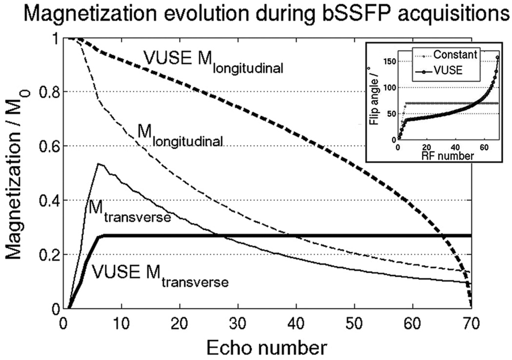
The overall signal in a transient bSSFP acquisition can be improved by fully utilizing the magnetization, rather than allowing the magnetization to approach steady state. Full utilization comprises (1) using a series of variable flip angles to convert all of the longitudinal magnetization to transverse magnetization while (2) maintaining a predefined, arbitrary signal profile shape over the acquisition block. Figure 1 demonstrates the main idea of this work with a specific example. A uniform signal profile shape (VUSE Mtransverse) is set as a target and achieved by using a series of non-linearly increasing flip angles. The signal amplitude is maximized such that the longitudinal magnetization at the end of the acquisition block is close to zero, i.e., it is used up.
Figure 1.
In a regular bSSFP acquisition that occurs intermittently, the magnetization (Mtransverse and Mlongitudinal) often never reaches steady state. A temporally uniform echo signal (VUSE Mtransverse, bold solid line) can be achieved by calculating a flip angle series that uses up all of Mlongitudinal by the end of the acquisition block. Inset shows the flip angle series used for the regular (constant) and VUSE bSSFP acquisitions.
The concept of using a series of variable flip angles is not new. In fast spin echo (FSE, a.k.a. RARE, TSE), variable flip angles are routinely used to mitigate power deposition or SAR limitations [10, 11]. In RF-spoiled gradient echo (SPGR) imaging, variable flip angles have been applied to time-of-flight MR angiography to reduce spatially varying saturation of moving spins, e.g., MOTSA, TONE [12]. In bSSFP, variable flip angles have been used to improve SNR for 2D imaging [13] and subtractive imaging [14]. The algorithms for calculating a series of variable flip angles for FSE [15] and SPGR [16–18] have been developed. However, the forward calculation of flip angles directly from desired echo amplitudes for bSSFP has never been published to our knowledge. This work demonstrates an analytical, closed-form expression that returns the flip angle based on the preceding and desired magnetization in bSSFP.
Although we are not targeting the steady state, an appropriate catalyzation preparation scheme is still required to minimize signal oscillations (magnitude and phase) and associated artifacts. Stable echo amplitudes and phases are important, especially in bSSFP, to minimize imaging artifacts. Common catalyzation schemes are the α/2-TR/2 pulse [4], linearly increasing ramp [5,7], and Kaiser-windowed ramp [8]. Le Roux has demonstrated that the Kaiser-windowed ramp is a simple and very effective scheme to minimize oscillations over a wide and controllable range [8]. In this work, we will implement the Kaiser ramp catalyzation with all bSSFP acquisitions to minimize artifacts. We will also use the matrix Bloch formulation to present the calculations and simulations performed in the work presented here [6, 19, 20].
In summary, this work aims to demonstrate a method for calculating flip angles to generate echoes at predefined amplitudes in balanced SSFP. The method also optimizes the integral of the signal versus time curve for any arbitrary signal profile. We present this work first by simulations, followed by phantom experiments and finally with volunteer imaging using an inflow-based MR angiography technique.
Theory
We present a simple algorithm to calculate flip angles to produce a prescribed shape of echo amplitudes, which can then be used iteratively to maximize the overall signal. A desired signal profile shape is defined based on an array of target echoes MT (n) over the acquisition block.
Flip angle calculation
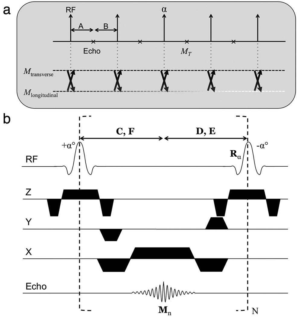
The flip angle calculation is more complicated in bSSFP than in SPGR because both longitudinal and transverse magnetization need to be considered at each repetition. In SPGR, transverse magnetization is assumed to be zero at the end of each repetition; however in bSSFP, both transverse and longitudinal magnetization affect the next echo signal (see Fig. 2a).
Figure 2.
(a) At each repetition, the RF pulse determines the degree to which the transverse and longitudinal magnetization affect the following echo. The evolution of the magnetization is fully described by the Bloch equation during the intervals A and B. We can therefore calculate an appropriate RF flip angle α to achieve a target echo amplitude MT. (b) Balanced SSFP pulse sequence diagram. Matrices C, D and vectors E, F describe T1/T2 relaxation of the magnetization during the periods indicated. C and D also describe precession of the magnetization that has non-zero components at off-resonance. See Appendix for detailed expressions of the matrices and vectors.
The effect of relaxation before and after the echo (intervals A and B in Fig. 2a) is easily described by the Bloch equation. The RF flip angle determines the degree to which the transverse and longitudinal magnetization affects the subsequent echo. The important development in this work is the analytical inversion of the Bloch equation to calculate an RF flip angle such that the target echo amplitude MT (n) is achieved each repetition. In other words, the nth flip angle is a deterministic function of the preceding and desired magnetization, flip(n) = f(MT (n − 1), MT (n), TR, …).
Signal optimization algorithm
Arbitrary optimality criteria are used: a series of flip angles is modified such that (1) the echo amplitudes are uniform and (2) the integral of the MT (n) versus time curve is maximized. These criteria are chosen mainly to ensure that the acquired data accurately represent the object of interest. More complex criteria that take into account tissue contrast and power deposition issues could be worked into the algorithm but a simple approach is used for example here. In the optimized case, the longitudinal magnetization is close to zero at the end of the acquisition block. It is almost impossible to determine the optimized series of MT (n) analytically so an iterative method is used: a series of MT (n) is chosen and we attempt to calculate a flip angle scheme; if it is achievable, we try another higher-valued series of MT (n) otherwise we try a lower-valued series of MT (n). In this case, higher- and lower-valued series are simply higher and lower uniform signal amplitudes. Using an interval and bisection approach, the convergence is quick and takes about twelve iterations to reach an error of less than 0.0005M0. The algorithm typically takes less than 50 ms to calculate a flip angle scheme for 64 echoes on a standard personal computer.
Further details of the algorithm and bSSFP flip angle calculations are presented in the Appendix. There are many desirable signal profiles, but a simple case is uniform signal amplitude, which we call “variable angle for uniform signal excitation” (abbreviated as VUSE following [18]). It is important to note that the choice of MT and the definition of higher- or lower-valued MT is somewhat arbitrary. For example, MT could be linearly increasing to some maximum and the change between iterations could be the slope.
Methods
All studies were performed using a 1.5 T MRI body scanner (GE Healthcare, Waukesha, WI). Informed consent was obtained from all subjects and all examinations were performed following our institution’s IRB protocol. A regular 3D bSSFP pulse sequence with Kaiser-windowed [8] ramp (five RF pulses) catalyzation was modified to perform variable flip angle calculations on-the-fly. The uniform signal profile VUSE was used as the target profile shape for all experiments hereon. The Kaiser ramp calculation was such that the RF flip angles were proportional to the cumulative sum of the Kaiser window (β = 2.0), where the window ends with the first acquisition flip angle (which equals the inverse sine of the target echo amplitude). Varying flip angles per acquisition were achieved by modifying the amplitude of the RF pulse (sinc pulse, with duration 0.8–1.8 ms depending on the peak flip angle of the series).
Simulations
All simulations were performed using the numerical matrix Bloch formulation as described in the Appendix. The effects of (1) off-resonance, (2) different T1 and T2 and (3) B1 sensitivity were investigated.
It is useful to study off-resonance by comparing the echo amplitudes from VUSE and the constant flip angle (i.e., regular bSSFP) acquisition. An acquisition block of 64 echoes was used, with a nominal T1/T2 = 907/50 ms (to match the relaxation values of the MRI phantom used later). The VUSE flip angle series was first calculated using the method described earlier. Next, the flip angle scheme was used to simulate the magnetization for on- and off-resonant spins; off-resonant frequencies (Δf) ranged from 0 to ±0.5×TR, where TR = 3.8 ms, TE = 1.9 ms. The magnetization were compared with those obtained using a constant flip angle of 70°.
Next, the magnetization for spins with different T1 and T2 were calculated using the same Bloch simulation and VUSE flip angle series. The same simulation parameters were used as for the on-resonant case in the previous experiment. Simulations were performed for spin species with varying T1 and T2 factors. Three different sets of simulations were done: (a) varying T1, constant T2, (b) varying T2, constant T1 and (c) varying both T1 and T2 but keeping their ratio constant. The effective decay λ of the on-resonant, transient magnetization has been shown to be a function of T1, T2 and flip angle α [9, 21]:
| (1) |
where E1,2 = eTR/T1,2. Therefore, a somewhat proportional effective decay change was expected as the relaxation parameters are modified.
The last simulation experiment investigates B1 sensitivity. Often in MRI, the actual flip angle does not correspond to the desired flip angle due to hardware limitations, and the resulting effect is called B1 sensitivity. To simulate this behavior, proportionally higher or lower flip angles compared to the ideal case were played, assuming that the B1 sensitivity is linearly dependent on the flip angle. B1 variations of 0.8×, 0.9× and 1.2× the desired flip angle amplitude were tested.
MRI phantom acquisition
Experiments performed in this section verify the simulation results and investigate the effect of VUSE on the apparent spatial resolution. A 3D bSSFP acquisition was used with phase encoding turned off. A birdcage head coil was used to provide a uniform B1 field. A ball agar phantom (T1/T2 = 907/50 ms) was used. The acquisition matrix (no phase encoding) was 256 × 64 × 10 (readout × echoes × slices) with each acquisition block acquiring 64 echoes. The interval between acquisition blocks was greater than 5×T1 (for full magnetization recovery). Other parameters were: FOV = 24 cm; slice thickness = 2.0 mm; TR (constant flip angle = 70°) = 3.8 ms; TR (VUSE) = 4.1 ms. The TR was higher in VUSE bSSFP to accommodate the large peak flip angle due to peak B1 and SAR (mean-squared ratio of flip angles in VUSE to regular bSSFP = 1.2) limitations. Echoes from the center slices were measured to avoid errors from imperfect slice excitation and compared with simulations obtained earlier.
Next, a separate acquisition of a phantom with features was used to demonstrate the resolution effects of VUSE. In MRI, modulation of k-space is directly related to the apparent resolution (i.e., point spread function). A linear, sequential acquisition ordering was used with the 3D bSSFP acquisition. The phase encode (y) direction was implemented as the inner loop and all ky lines per slice (i.e., each kz plane) were acquired in a single acquisition block. This ordering was chosen so that the effects of k-space modulation could be observed in-plane. Again, the interval between acquisition blocks was greater than 5×T1. Other parameters used were: matrix = 256 × 64 × 16; FOV = 17 cm; slice thickness = 1.5 mm; TR (constant flip angle = 70°) = 5.2 ms; TR (VUSE) = 5.8 ms.
MRI volunteer acquisition
An inflow-sensitive, non-contrast-enhanced MRA technique [22] was used in this section to demonstrate the image quality improvement using VUSE bSSFP.
The basic MRA pulse sequence comprised a bSSFP acquisition with two inversion recovery (IR) preparation pulses: a spatially selective IR (for background tissue and venous suppression) and a fat-selective IR. The 3D MRA acquisition was modified to acquire renal angiograms with the VUSE method, and imaging was performed in two healthy volunteers. An 8-channel phased array coil was used. Common parameters between regular bSSFP and VUSE bSSFP were: readout resolution = 256; readout FOV = 27–33 cm; phase FOV = 17–20 cm; slice thickness = 1.5–1.6 mm; TI = 1.0–1.1 s; with linear sequential acquisition ordering, fat-selective IR and respiratory triggering. Each kz plane was acquired in one (phase resolution = 77) or two (phase resolution = 154) acquisition blocks. The time between the start of consecutive acquisition blocks was one respiratory interval, typically 2.4–4.0 s. The number of slices (i.e., 3D sections) acquired ranged from forty to fifty, leading to total acquisition times of two to four minutes. The volunteers were imaged with VUSE (TR = 5.6 ms) and regular bSSFP (flip angle = 60°, 70°; TR = 4.6 ms, 5.1 ms). As before, the TR was higher in VUSE bSSFP due to the higher flip angles used towards the end of the acquisition block.
Results
Simulations
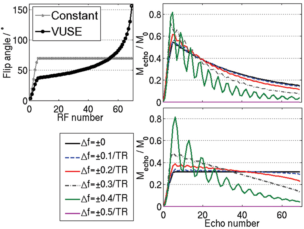
The optimized VUSE flip angle scheme and constant flip angle scheme are shown in Fig. 3a. The resulting simulated transverse magnetization is also shown for spins at on- and off-resonance (Fig. 3b and 3c). The oscillations in the regular bSSFP and VUSE bSSFP are comparable. Note that oscillations are small near resonance, and the echo amplitudes are not significantly impacted. Further off-resonance, there are oscillations as predicted by [8] and some loss of signal. The off-resonance behavior is symmetric about zero frequency and is periodic, repeating every 1/TR Hz. An alternate interpretation is given by larger “effective” flip angles [21], leading to faster decay as λ (Eq. 1) becomes more T2- than T1-weighted.
Figure 3.
Echo amplitudes from simulations of on- and off-resonant spins for (b) constant flip angle bSSFP and (c) VUSE bSSFP (Δf = off-resonant frequency). A flat echo profile is achieved in VUSE on-resonance. The flip angle schemes used are shown in (a). Both acquisitions have comparable oscillations off-resonance owing to the Kaiser-ramp catalyzation (initial five RF pulses). Note also that the off-resonance behavior is symmetric about zero, and it has a periodicity of length 1/TR.
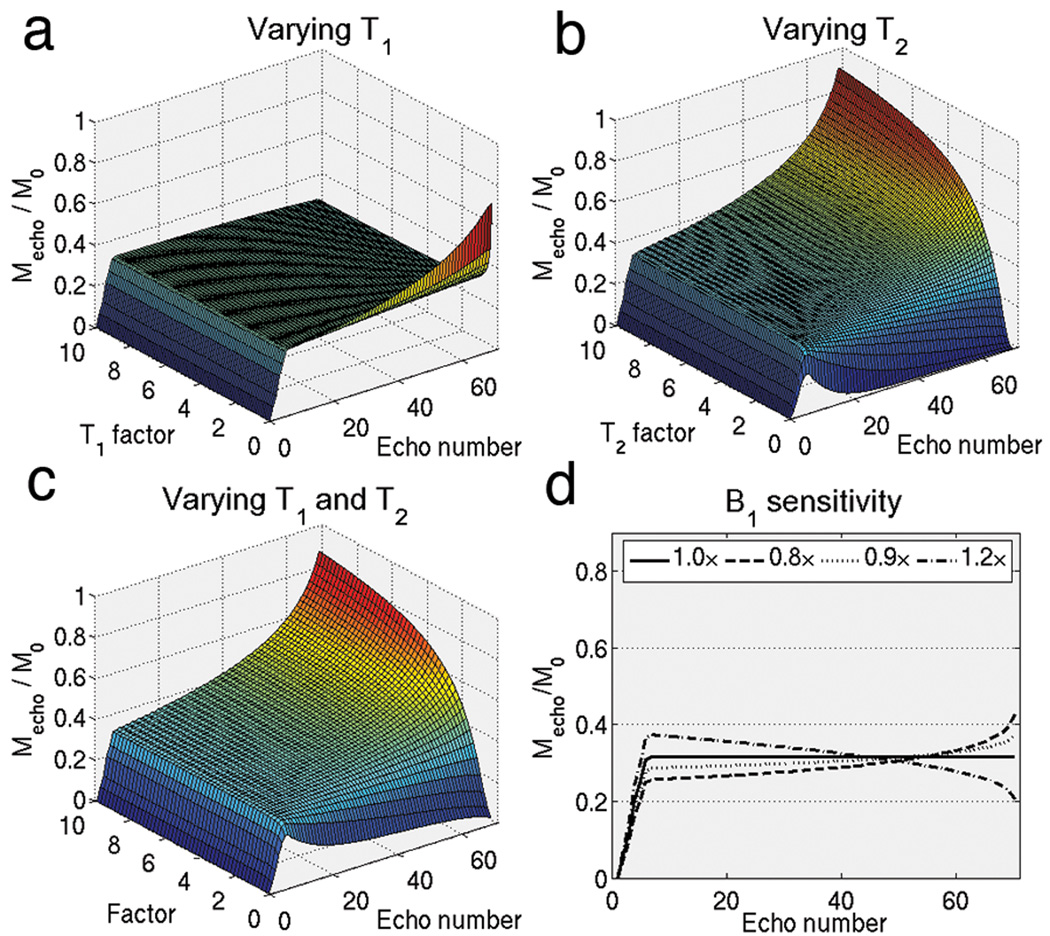
Figure 4a–c plots the effect of VUSE variable flip angles on species with different relaxation times. The uniform echo profile appears to suffer more from T2 deviation than T1 deviation. Also, underestimation of T1 causes the profile to increase whereas underestimation of T2 causes the profile to decrease, and the opposite happens for overestimation of relaxation parameters. Considering image signal, the simulations suggest that it is better to underestimate T2 and overestimate T1 when calculating the variable flip angle series. Regardless of the sign of the deviation, the effects of T1 and T2 deviations on VUSE bSSFP are relatively benign and results in a slowly varying signal profile without any signal oscillations.
Figure 4.
Using the same flip angle scheme shown in Fig. 3a that was calculated using T1/T2 = 907/50 ms, echo amplitudes were simulated at (a) various T1 factors, (b) various T2 factors, (c) various T1 and T2 factors but keeping ratio of T1/T2 the same and (d) at various B1 factors. Other relaxation species are not adversely affected by the variable flip angles. Slice profile effects could be inferred from the plots in (d). All of these sensitivities do not cause oscillations, instead they result in smooth modulation of k-space weighting.
Figure 4d plots the B1 sensitivity of VUSE bSSFP. Like with T1 and T2, the B1 sensitivity is somewhat mild in VUSE bSSFP and result in a smooth modulation of the signal profile shape. Although not shown here, regular bSSFP has an equally strong shape dependence on flip angle [21].
MRI phantom acquisition
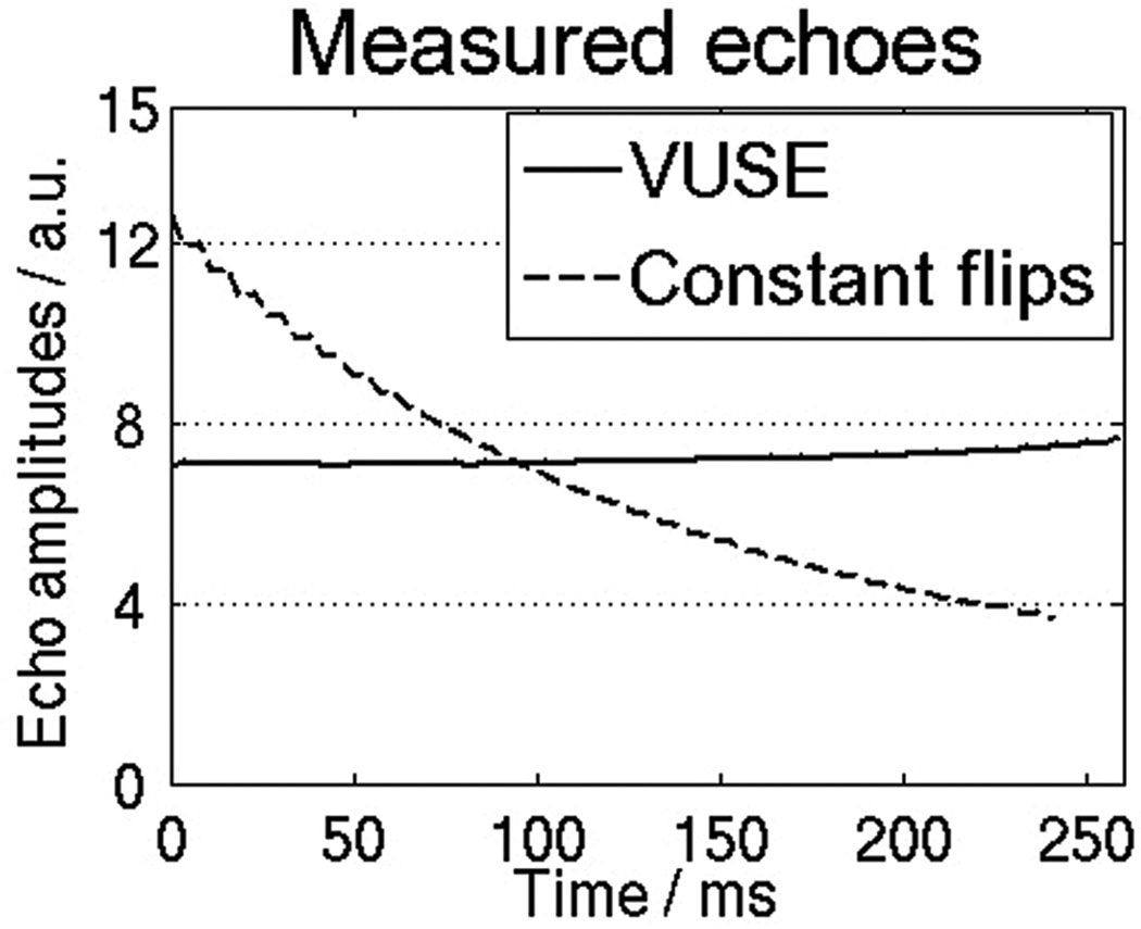
Figure 5 shows the expected decaying and uniform signal profiles from constant flip angle bSSFP and VUSE bSSFP. The relative amplitudes of the measured signals are similar to those of the on-resonant spins simulated in Fig. 3.
Figure 5.
Plots of MRI signal (in arbitrary units) versus time for the constant (70°) and VUSE flip angle schemes. The target echo profile using VUSE was a uniform signal profile. VUSE bSSFP took more time than constant flip angle bSSFP due to an increased TR (due to high flip angles used towards the end of the series).
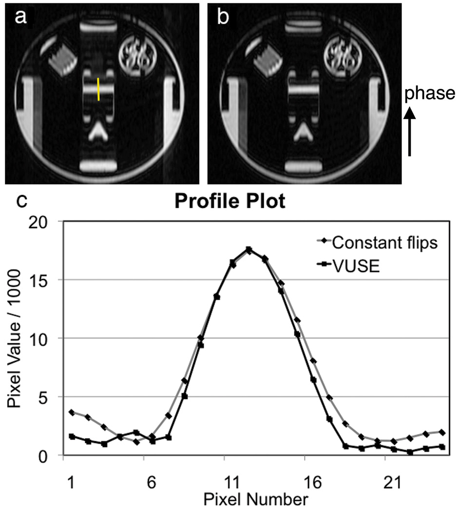
Spatial resolution differences between the constant flip angle and VUSE acquisitions using linear sequential acquisition ordering are shown in Fig. 6. The results demonstrate an improvement using VUSE bSSFP. This is intuitive since the full-width-half-maximum of the Fourier Transform of a box function is less than that of the Fourier Transform of a one-sided, decaying exponential.
Figure 6.
Images of the slice used to plot a line profile for assessing the effective spatial resolution in a linear sequential acquisition using (a) constant flip angles and (b) VUSE. (c) Measured line profile plots (from the yellow line in (a)) demonstrate an increased apparent spatial resolution using VUSE.
MRI volunteer acquisition
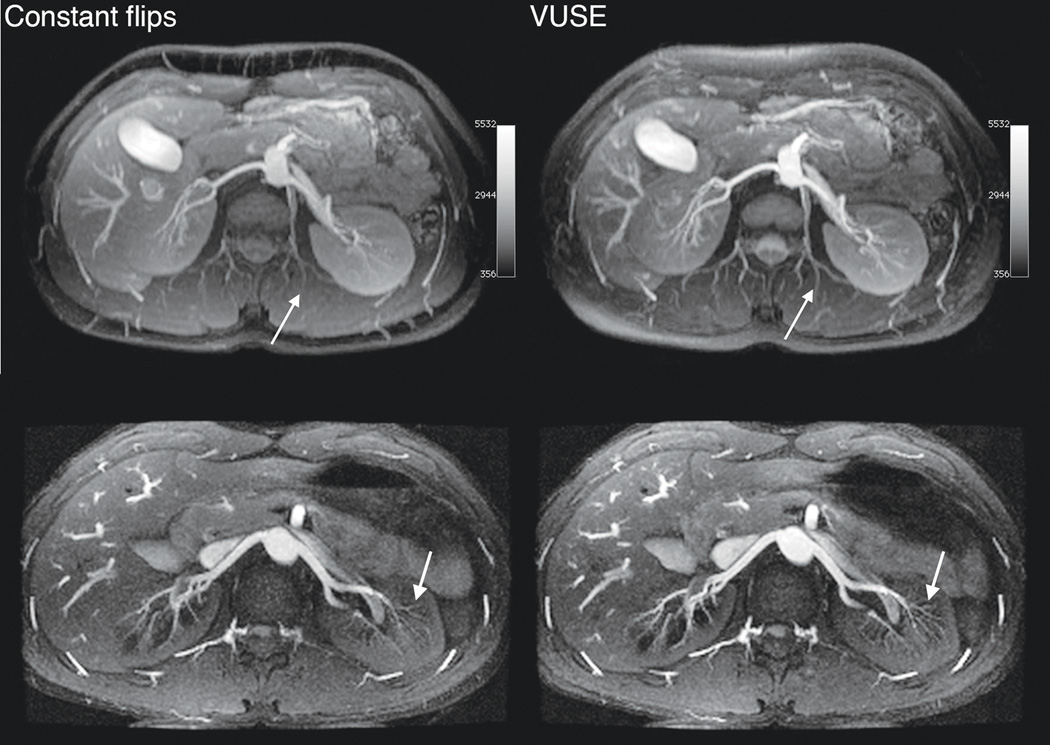
VUSE bSSFP angiograms have higher signal and improved small vessel depiction compared to regular bSSFP angiograms (Fig. 7), which is attributed to the higher echo amplitude at k-space center and optimized integral of signal versus time. Fat suppression is poorer in one volunteer using VUSE due to increased TR resulting in sub-optimal fat nulling with the fat-selective IR; this can be remedied by reducing the length of the acquisition block, as illustrated in images from the second volunteer.
Figure 7.
Axial MIP renal angiograms from MRA acquisitions using constant flip angle (60°, upper left, and 70°, lower left) and VUSE bSSFP. In the second (bottom) volunteer, each kz plane was acquired in two acquisition blocks (ky interleaved). Images acquired using VUSE bSSFP has higher signal and improved small vessel depiction (white arrows). Each row is displayed at the same window and level.
Discussion
We have developed a simple method of calculating flip angles to achieve a series of predefined echo amplitudes in transient bSSFP imaging. The method was successfully demonstrated using the example of a uniform signal profile that we have called VUSE bSSFP. No additional artifacts were observed in the images acquired using VUSE bSSFP compared to those from regular bSSFP.
We also demonstrated improved image quality in respiratory-gated, inflow-based non-contrast-enhanced renal angiography using VUSE bSSFP. In fact, inflow-based angiography has two characteristics that make it particularly favorable for variable flip angle transient bSSFP imaging. (1) Only a single species (i.e., blood) is of interest; the signal and contrast from tissue and fat is low and not of concern. (2) Inflowing arterial blood has full magnetization at the start of each acquisition block. The combination of these factors makes inflow bSSFP angiography particularly amenable to variable flip angle optimization.
This variable flip angle technique can be applied to most transient bSSFP imaging scenarios/applications to improve signal, e.g., physiologically triggered acquisitions, 2D imaging and magnetization prepared acquisitions. The benefit is probably lower in certain magnetization-prepared acquisitions where the spins are characterized more closely by the steady state than the transient stage. One such example is a fat-saturation prepared sequence where the magnetization is maintained close to steady state [23]. In other words, the greatest benefit can be reaped when there is an interim period where the magnetization of interest can recover.
The application of variable flip angle bSSFP is not limited to the uniform case and can be optimized for a ramped, windowed or other shape profile depending on the application. A windowed shape profile can be used when, for example, trying to increase apparent signal by acquiring k-space center with high echo amplitudes. That is to say, with a particular imaging requirement (e.g., high signal, high spatial resolution or minimum power deposition), and taking into account the acquisition ordering [11,24], a variable flip angle series can be calculated that provides an arbitrary echo profile shape that has been optimized for the application. The signal profile shape could also be part of the signal optimization algorithm. We reiterate that the optimization step/change during which a higher- or lower-valued target signal profile is tested can be arbitrarily defined. In the case of VUSE, the change is a simple amplitude increase or decrease. When the signal profile is non-uniform, more parameters may be required to describe the change, and in some cases, the iteration would not be stable.
Improved apparent spatial resolution was demonstrated using VUSE in an MRI phantom in our experiments. The degree of benefit depends heavily on the acquisition ordering (i.e., how k-space is traversed). A linear sequential ordering was used such that each kz plane was acquired in one acquisition block. Thus, the effect of the uniform signal profile shape was directly observed in the in-plane phase encode features. Phantom data (not shown) were also acquired using a 3D elliptical centric acquisition ordering. However, in this latter case, improvements in spatial resolution were not observed with the in-plane features, probably because the effect was distributed in both the phase and slice directions. Therefore, it is important to consider the acquisition ordering when predicting the effects of the signal profile shape. Improved spatial resolution is not necessarily observed when using VUSE bSSFP; the general effect of k-space modulation on SNR, contrast and spatial resolution requires more rigorous analysis and is beyond the scope of this paper.
The motivation of this work is similar to [13] in that improved signal is achieved by imaging in the transient stage. The aim of that work was to improve signal while maintaining power deposition, and employed a trial-and-error approach at a range of flip angles. In this work, we used a systematic approach to achieve a predefined signal profile shape during the transient stage while optimizing for the integral of the signal versus time. Also, in our work, spatial resolution effects can be predicted and manipulated by considering the k-space modulation due to the signal profile shape.
Several catalyzation schemes have been developed with the common purpose of minimizing signal oscillations as the imaging approaches the steady state. We have used the Kaiser-windowed ramp scheme in this work as it has been shown to be effective at minimizing these oscillations [8]. More importantly, the extent of the oscillations is about the same in variable flip angle bSSFP and constant flip angle bSSFP. Therefore, if the α/2 pulse or linear ramp were used with VUSE, we would expect comparable oscillations to similarly catalyzed regular bSSFP.
The Kaiser ramp catalyzation was adapted for use in variable flip angle imaging such that first imaging flip angle was reached at the end of the catalyzation scheme. The first imaging flip angle was defined as the inverse sine of the target echo amplitude. However, due to decay during the finite length of the catalyzation, the echo amplitude at the end of the catalyzation was smaller than that of the target amplitude. In actual imaging, this discrepancy is usually not noticeable. The algorithm can be easily tweaked to take into account the Kaiser ramp catalyzation. Also, acquisition can usually start in the same repetition as the final Kaiser ramp pulse instead of after the catalyzation, allowing for one more echo to be acquired per acquisition block.
Limitations of VUSE bSSFP include increased TR and B1 sensitivity, both of which arise from the use of high flip angles towards the end of the acquisition block. Regular bSSFP also suffers from increased TR due to peak B1 limitations (due to hardware constraints and physiological variations) and SAR limitations typically for flip angles greater than 50–70° (depending on the RF pulse used and magnetic field strength). In our experiments, peak B1 was the primary reason for increased TR when using VUSE; however, the limiting factor could shift to SAR when higher magnetic field strengths are used. Increased TR results in reduced imaging efficiency and possibly increased sensitivity to motion. These limitations can be avoided by limiting the maximum flip angle allowed in the flip angle calculation algorithm, at the expense of reduced signal improvement. On a related note, depending on the signal profile desired, the peak flip angles need not always occur at the end of the acquisition block.
The variable flip angle method demonstrated here has been used to optimize the signal profile of a single species with a specific T1/T2. Figure 4a–c show that the effect of VUSE on other species is relatively mild; the signal profiles are non-uniform but not wildly varying (i.e., no oscillations). In particular, blurring or increased noise of other species could occur depending on the particular k-space acquisition ordering. Also, these effects on the signal profile shape also apply in regular bSSFP. If more than one species were of interest, the algorithm could be adapted to optimize the signal profiles of more than one species.
In bSSFP, due to short RF pulse widths, the excitation slice profile is far from the ideal box function. Therefore, the flip angles achieved at the slice edges are lower than those at the center. In the phantom experiments, echo amplitudes were measured from the center slices of a 3D acquisition to avoid slice profile effects. However, the simulations at varying B1 sensitivities in Fig. 4d provide insight as to what the signal profile might be for spins at the slice edges.
The relationship between VUSE bSSFP and power deposition has not been rigorously analyzed in this work, but insight to this relationship can be drawn from the flip angle versus time curve. The mean-squared B1 amplitude over time is proportional to the power deposition and is not much/necessarily higher in the VUSE case compared to regular bSSFP (Fig. 3a); certainly, the exact difference depends on the specific flip angle schemes used. Although not shown here, the ratio of the integral of the signal-versus-time-curve to power deposition could be increased when this requirement is included in the signal optimization algorithm, similar to [13].
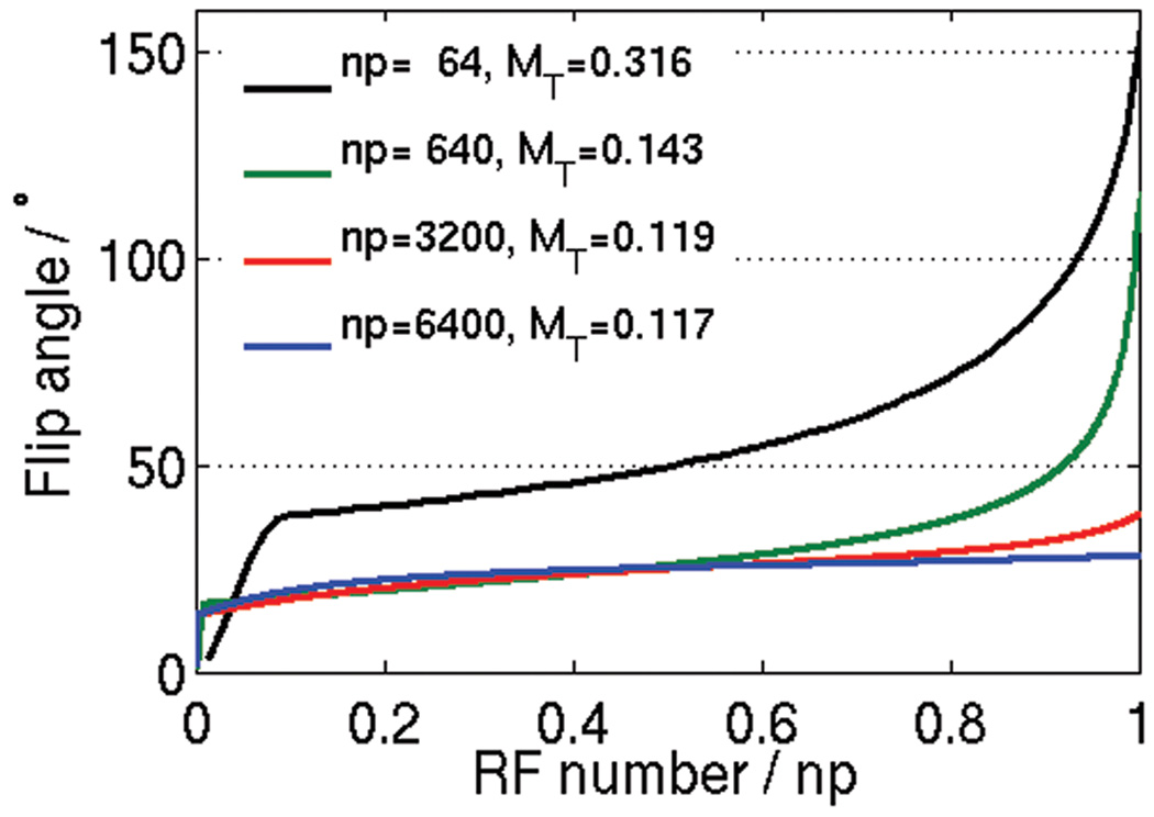
This research leverages the longitudinal magnetization that remains after each repetition to increase the acquired signal. Especially when the magnetization is truly transient, e.g., when imaging inflowing blood or 2D acquisitions, more signal can be gained with variable flip angles than simply choosing any constant flip angle. Using the variable flip angle method allows for all of the longitudinal magnetization to be converted to the transverse magnetization for signal formation. When the magnetization is not truly transient, i.e., the magnetization experiences more than one acquisition block in rapid succession (< 5×T1), the full use of the magnetization by the end of the acquisition block might not be the most efficient or signal optimal. The optimization algorithm could be adjusted to take into account this “less transient” magnetization and use a more suitable optimality criterion. It is interesting to see how the VUSE flip scheme evolves as the number of acquisition pulses increases (Fig. 8). The uniform, target echo amplitude is expected to decrease as the number of acquisition pulses increases. A similar result is observed when the magnetization becomes decreasingly transient as the magnetization experiences several acquisition blocks without achieving full relaxation between the blocks. Also, Fig. 8 shows that the flip scheme tends towards the constant, optimal flip angle as the number of acquisition pulses increases per acquisition block.
Figure 8.
VUSE flip angle schemes for varying number of RF pulses (np) per acquisition block using the same parameters as for Fig. 3. As np increases, the uniform, target echo amplitude (MT) decreases and the flip angle scheme tends towards the optimal, constant flip angle of cos−1[(T1/T2−1)/(T1/T2+ 1)] = 26°.
Conclusion
We have presented a method for calculating the flip angle required to produce a desired echo amplitude in transient bSSFP imaging. Using this formulation, predefined signal profile shapes can be iteratively optimized and achieved, as demonstrated by Bloch simulations and MRI phantom acquisitions. We have also effectively demonstrated the signal improvement using variable flip angle bSSFP in volunteers using inflow-based bSSFP MR angiography.
Acknowledgments
Grant Sponsors:
This work was supported by NIH R01 EB009055-01, NIH P41 RR009784-11, the Lucas Foundation and General Electric Healthcare.
The authors would like to thank Marcus Alley for helpful discussion.
Appendix
Theory
The matrix formulation as described by Jaynes [19] was used to simulate Bloch dynamics in bSSFP. The spin dynamics in one TR, where it undergoes excitation, precession and relaxation, can be expressed as
| (2) |
where Mn is the net magnetization vector at the start of the nth period, A is a 3 × 3 matrix and B is a 3-row vector. A and B are given in [6] and describe the relaxation, precession and excitation processes. The vector B is disjointed from Mn as it is associated with the recovery of the longitudinal magnetization.
Therefore, A and B can be expanded as
| (3) |
| (4) |
where C and D are 3 × 3 matrices, E and F are vectors and .
Figure 2b illustrates the parts of the pulse sequence that are effected by C, D, E, F and Rα.
We will use an RF excitation axis along ±y such that the echoes are generated along the x axis, i.e. Mx ≠ 0. For the full echo, on-resonance case,
| (5) |
| (6) |
where τ = TE = TR/2.
The aim here is to determine a flip angle α such that Mn+1,x = Mn,x without constraining Mz. We will refer to the target Mx echo amplitude as MT. Now we can rewrite Eq. 2 as
| (7) |
The second component of the evaluated vector becomes
| (8) |
where E1 and are always zero for the on-resonance case (following Eq. 5 and 6).
Solving for α gives
| (9) |
where .
Algorithm
Starting from M0 = [0 0 1]T, a sequence of flip angles is first calculated for the Kaiser ramp dummy acquisitions. For example, in the case of five dummy acquisitions, the amplitudes of the five flip angles are determined such that the sixth flip angle is equal to . We can then use Eq. 9 to iteratively calculate the remaining sequence of flip angles for achieving MT.
In the VUSE method (and [15]), it is difficult to predict what the maximum target amplitude MT is for a specific tissue species, TR and acquisition block length. For now, we will determine this amplitude using an iterative approach: an MT is chosen and we try to calculate a flip scheme; if the flip angle scheme is achievable, we try another higher-valued MT, otherwise, the flip angle solution to Eq. 9 is imaginary and we bisect the interval and try again. The upper and lower bounds of the first interval of the iteration are given by M0 and the steady-state amplitude.
Specifically, the steps are as follows:
- Initialize variables. Set the target amplitude MT and test interval bounds [Mlower, Mupper].
(10) (11)
where M0 = 1.0 and MSS = steady-state amplitude as given in [25].(12) - Calculate VUSE flip scheme. The algorithm is completed when the interval size is less than converge_limit ~ 0.0005M0.
- finish_calcs = 0
-
do {
- Kaiser ramp RF pulses to
-
mt_not_possible = 0for 1 : number of pulses {
- Calculate α for achieving MT as in Eq. 9
- if α is not real {
- mt_not_possible = 1
- break
- }
} -
if mt_not_possible == 1
- Mupper = MT
else- Mlower = MT
-
if (Mupper − Mlower) > converge_limit
- MT = (Mupper − Mlower)/2
else- finish_calcs = 1
- } while (finish_calcs == 0)
MATLAB code for VUSE can be found at http://www.stanford.edu/~worters/software.
References
- 1.Oppelt A, Graumann R, Barfuss H, Fischer H, Hartl W, Shajor W. FISP – a new fast MRI sequence. Electromedica. 1986;54:15–18. [Google Scholar]
- 2.Markl M, Alley MT, Elkins CJ, Pelc NJ. Flow effects in balanced steady state free precession imaging. Magn Reson Med. 2003;50:892–903. doi: 10.1002/mrm.10631. [DOI] [PubMed] [Google Scholar]
- 3.Carr HY. Steady-state free precession in nuclear magnetic resonance. Phys. Rev. 1958;112:1693–1701. [Google Scholar]
- 4.Deimling M, Heid O. Magnetization prepared true FISP imaging. Proceedings 2nd Scientific Meeting, International Society for Magnetic Resonance in Medicine; Honolulu. 1994. p. 495. [Google Scholar]
- 5.Nishimura DG, Hargreaves BA. Analysis and reduction of the transient response in SSFP imaging. Proceedings 8th Scientific Meeting, International Society for Magnetic Resonance in Medicine; Denver. 2000. p. 301. [Google Scholar]
- 6.Hargreaves BA, Vasanawala SS, Pauly JM, Nishimura DG. Characterization and reduction of the transient response in steady-state MR imaging. Magn Reson Med. 2001;46:149–158. doi: 10.1002/mrm.1170. [DOI] [PubMed] [Google Scholar]
- 7.Deshpande VS, Chung YC, Zhang Q, Shea SM, Li D. Reduction of transient signal oscillations in true-FISP using a linear flip angle series magnetization preparation. Magn Reson Med. 2003;49:151–157. doi: 10.1002/mrm.10337. [DOI] [PubMed] [Google Scholar]
- 8.Le Roux P. Simplified model and stabilization of SSFP sequences. J Magn Reson. 2003;163:23–37. doi: 10.1016/s1090-7807(03)00115-0. [DOI] [PubMed] [Google Scholar]
- 9.Scheffler K. On the transient phase of balanced SSFP sequences. Magn Reson Med. 2003;49:781–783. doi: 10.1002/mrm.10421. [DOI] [PubMed] [Google Scholar]
- 10.Alsop DC. The sensitivity of low flip angle RARE imaging. Magn Reson Med. 1997;37:176–184. doi: 10.1002/mrm.1910370206. [DOI] [PubMed] [Google Scholar]
- 11.Hennig J, Weigel M, Scheffler K. Multiecho sequences with variable refocusing flip angles: optimization of signal behavior using smooth transitions between pseudo steady states (TRAPS) Magn Reson Med. 2003;49:527–535. doi: 10.1002/mrm.10391. [DOI] [PubMed] [Google Scholar]
- 12.Wang SJ, Nishimura DG, Macovski A. Multiple-readout selective inversion recovery angiography. Magn Reson Med. 1991;17:244–251. doi: 10.1002/mrm.1910170127. [DOI] [PubMed] [Google Scholar]
- 13.Paul D, Zaitsev M. Improved SNR in linear reordered 2D bSSFP imaging using variable flip angles. Magn Reson Imaging. 2009;27:933–941. doi: 10.1016/j.mri.2009.01.021. [DOI] [PubMed] [Google Scholar]
- 14.Smith T, Zun Z, Wong EC, Nayak KS. Design and use of variable flip angle schedules in transient balanced SSFP subtractive imaging. Magn Reson Med. 2010;63:537–542. doi: 10.1002/mrm.22255. [DOI] [PubMed] [Google Scholar]
- 15.Hennig J, Weigel M, Scheffler K. Calculation of flip angles for echo trains with predefined amplitudes with the extended phase graph (EPG)-algorithm: principles and applications to hyperecho and TRAPS sequences. Magn Reson Med. 2004;51:68–80. doi: 10.1002/mrm.10658. [DOI] [PubMed] [Google Scholar]
- 16.Stehling MK. Improved signal in “snapshot” FLASH by variable flip angles. Magn Reson Imaging. 1992;10:165–167. doi: 10.1016/0730-725x(92)90387-f. [DOI] [PubMed] [Google Scholar]
- 17.Mugler JP, Epstein FH, Brookeman JR. Shaping the signal response during the approach to steady state in three-dimensional magnetization-prepared rapid gradient-echo imaging using variable flip angles. Magn Reson Med. 1992;28:165–185. doi: 10.1002/mrm.1910280202. [DOI] [PubMed] [Google Scholar]
- 18.Priatna A, Paschal CB. Variable-angle uniform signal excitation (VUSE) for three-dimensional time-of-flight MR angiography. J Magn Reson Imaging. 1995;5:421–427. doi: 10.1002/jmri.1880050409. [DOI] [PubMed] [Google Scholar]
- 19.Jaynes ET. Matrix treatment of nuclear induction. Physical Review. 1955;98:1099–1105. [Google Scholar]
- 20.Ganter C. Off-resonance effects in the transient response of SSFP sequences. Magn Reson Med. 2004;52:368–375. doi: 10.1002/mrm.20173. [DOI] [PubMed] [Google Scholar]
- 21.Schmitt P, Griswold MA, Gulani V, Haase A, Flentje M, Jakob PM. A simple geometrical description of the TrueFISP ideal transient and steady-state signal. Magn Reson Med. 2006;55:177–186. doi: 10.1002/mrm.20738. [DOI] [PubMed] [Google Scholar]
- 22.Miyazaki M, Lee VS. Nonenhanced MR angiography. Radiology. 2008;248:20–43. doi: 10.1148/radiol.2481071497. [DOI] [PubMed] [Google Scholar]
- 23.Scheffler K, Heid O, Hennig J. Magnetization preparation during the steady state: fat-saturated 3D TrueFISP. Magn Reson Med. 2001;45:1075–1080. doi: 10.1002/mrm.1142. [DOI] [PubMed] [Google Scholar]
- 24.Busse RF. Reduced RF power without blurring: correcting for modulation of refocusing flip angle in FSE sequences. Magn Reson Med. 2004;51:1031–1037. doi: 10.1002/mrm.20056. [DOI] [PubMed] [Google Scholar]
- 25.Scheffler K, Lehnhardt S. Principles and applications of balanced SSFP techniques. Eur Radiol. 2003;13:2409–2418. doi: 10.1007/s00330-003-1957-x. [DOI] [PubMed] [Google Scholar]


