Abstract
Easy trap-and-release of microparticles is necessary to study biological cellular behavior. The hydraulic jump phenomenon inspired us to conceive a microfluidic device for the hydrodynamic trap-and-release of microparticles. A sudden height increase in a microfluidic channel leads to a dramatic decrease in flow velocity, allowing effective trapping of the microparticles by energy conversion. The trapped particles can be released by stronger inertial force based on simply increasing the flow velocity. We present a systematic, numerical study of trap-and-release of the microparticles using multiphase Navier–Stokes equations. Effect of geometry flow velocity, particle diameter, and adhesion force on trap-and-release was studied.
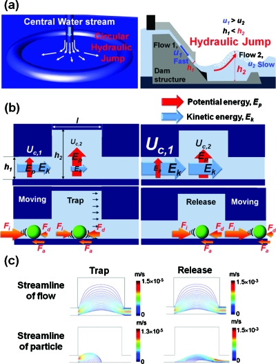
Manipulating microparticles, such as cells, bacteria, and hydrogel particles using microfluidics, is very important for high throughput and fast cell screening, single cell analysis, and biochemical synthesis.1, 2, 3, 4, 5 Manipulation methods usually apply acoustic,6 chemical,7 electrical,8 mechanical,9 magnetic,10 or optical gradients.11 In terms of microfluidic trapping of microparticles, techniques such as patch clamp, adhesion, sedimentation, size filtration, trench separation, and hydrodynamic trapping have been demonstrated.1, 4, 12, 13, 14, 15, 16, 17, 18, 19, 20, 21, 22, 23, 24, 25 However, these methods are limited by the absence of releasing capability. In this regard, a microparticle control method should easily trap-and-release microparticles using a simple design. In nature, there is one good example which meet these requirements as follows: the hydraulic jump phenomenon. This is often observed in open channel flow, such as spillways and dams. The hydraulic jump occurs when a liquid at high velocity discharges into a zone of lower velocity [Fig. 1a]. Due to a sudden decrease in fluid velocity, kinetic energy converts to potential energy, causing the fluid to “jump.” Here, we describe a hydrodynamic trap-and-release method inspired by the hydraulic jump in nature. The microfluidic implementation consists of a channel with a hydraulic jump cavity where there is a sudden expansion in height. Because of the sudden expansion of the microfluidic channel height, kinetic energy of the microparticles is converted to potential energy and eventually due to gravitational forces the microparticles settle down. At the channel floor, the microparticles get trapped when the fluid force on them is balanced by surface interaction forces. The trapped particle can then be easily released by stronger inertial force based on simply increasing of flow velocity. The increase in fluid velocity increases the fluid forces which overcome surface interaction forces, leading to particle release. In this simulation study, the geometrical factors, including height and length of the hydraulic jump cavity (for a specific microparticle diameter), and flow velocity are investigated for optimal hydrodynamic trap-and-release device. In addition, adhesion force between substrate surface and particles is considered for the trapping of 0.5 μm sized particles.
Figure 1.
Hydrodynamic trap-and-release phenomenon from hydraulic jump in nature; (a) circular hydraulic jump and hydraulic jump in nature; (b) hydrodynamic trap-and-release in hydraulic jump cavity; and (c) streamline comparison between flow and particle.
The trap-and-release motion of microparticles in a flow can be estimated by using continuity and Navier–Stokes equations. To solve for velocity, pressure, and volume fraction of the particles, the multiphase flow model is used for the mixture of particles and liquid.
In most of biomedical applications, the sizes of the microparticles, such cells and bacteria, typically range from 1 to 20 μm [Fig. 1b]. In this regard, the channel height, h1 should be in the range of 10–100 μm. For calculation, all geometric factors are normalized by h1. Therefore H (h2∕h1), L (l∕h1), and Dp (da∕h1) are the normalized height, length, and the diameter of a particle, respectively. This simulation of hydrodynamic trap-and-release was performed in a triangular grid using a COMPUTATIONAL FLUID DYNAMICS code.27
Throughout the channel, the flow energy is conserved. The type of energy can be converted based on the following equations: , u1,c×h1=u2,c×h2, where u1,c is the velocity of the liquid before entering hydraulic jump cavity and u2,c is the velocity of the liquid in hydraulic jump cavity. When a microparticle is present in the fluid, the inertial force, Fi∝[(u1,d−u2,d)∕Δt], the drag force, Fd∝(u2,c−u2,d), and the adhesion force, Fa∝(u1,c−u2,c) around the particle must be considered, u1,d is the velocity of the particle before entering hydraulic jump cavity, u2,d is the velocity of the particle in the hydraulic jump cavity, and Δt is the time period. The force balance (BF=Fi−Fd−Fa) around the particle is considered to determine the motion of the particle. Therefore, when a particle enters into the hydraulic jump cavity, the inertial force becomes drastically weak. Under this circumstance, the particle can be trapped. On the other hand, if the flow velocity, u1,c, increases, Fi becomes stronger (BF>0) and the trapped particle in the hydraulic jump cavity can be easily released. This hydrodynamic trap-and-release concept has significant advantages compared to conventional trench methods.27 In a trench structure, particles can be easily trapped by gravity; however, it is impossible to release the trapped particles from the trench. In comparison, the trap-and-release process in our method is truly reversible.
We estimated the streamlines of flow while particles trapped and released [Fig. 1c]. The streamlines of liquid phase smoothly flow from the inlet to the outlet. However, the streamlines of the particles asymmetrically terminate on the bottom of the channel, thereby trapping the particles at a certain distance from the inlet. The trapped particles are released by increasing flow rate. We define the distance from the inlet to the location of the trapped particle as trapping distance, Dt. The Dt was found to increase with increasing the height of the particle in the inlet channel.26
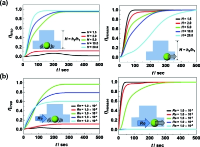
Since geometries of the hydraulic jump cavity are very important to achieve high trapping and releasing efficiency (ηtrap and ηrelease),27 these factors are systematically studied to optimize ηtrap and ηrelease [Fig. 2a]. Regarding the effect of H, ηtrap increases with H. While low H (=∼2.0) showed no trapping, ηtrap almost reaches 100% in 50 s using H=20. On the other hand, ηrelease decreases with increasing H. As time goes on, a profile change in trapping and releasing become saturated at a specific time, and this time is defined as saturation time, ts. In general, the releasing ts is longer than the trapping ts. Although ηtrap increases with H, considering practical fabrication steps (maximum height of photoresist at photolithography based microfabrication is ∼200 μm), maximum H is constrained to 20 for realistic designs. In the case of L, although ηtrap increases with L, the degree of increase is lower than compared with H. The trapping (ηtrap=0.6) occurred from L=6.5 and above, while ts increased from 100 to 200 s with L. Regarding the effects of L on releasing, to achieve ηrelease=1.0, ts becomes longer from 50 to 500 s with L (1.5–25.0).28
Figure 2.
Geometric effects and flow velocity on hydrodynamic trap-and-release; (a) the ηtrap and the ηrelease as a function of H at Dp=0.5 at Re=10−3; (b) the ηtrap and the ηrelease as a function of Re at H=5.0,L=6.5, and Dp=0.5.
For further estimation, we selected H=5.0 and L=6.5 as a representative design, because at this given geometry high ηtrap and ηrelease are reasonably obtained simultaneously. In this geometry, a time resolved ηtrap and ηrelease as a function of Reynolds number, Re, are calculated [Fig. 2b]. As Re increases, ηtrap increases while ηrelease decreases. In trapping, ηtrap is achieved from 0.6 to 0.8 by changing Re from 10−3 to 10−4, while, in the Re range from 10−1 to 10−2, the flow is too fast to trap particles. In releasing, even though ηrelease=∼1.0 is achieved for all Re numbers used here, ts of releasing decreased from 300 to 25 s by changing Re from 10−5 to 10−1.
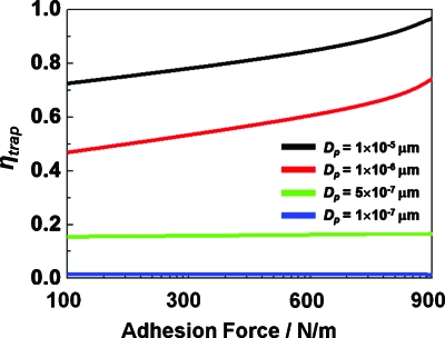
For biomedical applications of our hydraulic jump cavity, it is critical that particles of biologically relevant sizes can be efficiently trapped and released.26 For example, bacteria and mammalian cells range in size from 1 to 20 μm. In addition, the manipulation of biocompatible submicrometer size particles, such as hydrogel particles28 and multifunctional nanoprobes,29 is also necessary. In conventional static particle trapping, minimum controllable size of a particle is approximately 10 μm.5 However, the size for trapping can be further reduced by adding adhesion force. In general, it is reported that chemical surface treatment results in adhesion force between cell and substrate30 from 100 to 900 N∕m2. Therefore, in order to trap and release submicron particles, adhesion force effect is also considered in this study (Fig. 3). Increasing the adhesion force results in trapping of smaller particles and increasing ηtrap. The smallest size of trapped particles is 0.5 μm under adhesion force and under this condition, varying adhesion force has minimal effect on ηtrap. In the case of trapping efficiency, as adhesion force changes from 100 to 900 N∕m2, ηtrap changes from 0.45 to 0.75 for 1 μm particles.
Figure 3.
Particle size for trapping and ηtrap as a function of adhesion force; strong (500–900 N∕m2) and weak adhesion force (100–500 N∕m2).
In conclusion, hydraulic jump in nature phenomenon inspired the invention of our microscale hydrodynamic trap-and-release device. Resulting from a sudden height increase in the device, a significant decrease in flow velocity leads to trapping of microparticles by energy conversion. Reversely, the trapped particles are released by increased inertia force based on faster flow velocity. A systematic, numerical study of microparticle motion in the hydraulic jump cavity is reported here. The ηtrap increases with H and L, while high Re resulted in lower ηtrap. In addition, strong adhesion interaction (900 N∕m2) results in trapping of submicrometer sized particle. Hydraulic jump-based hydrodynamic trap-and-release method can be integrated into a microfluidic array to selectively control microparticles or living cells for quantitative analysis. It will provide a platform to manipulate living cells in physiological microenvironments of cell culture media and reagents.
Acknowledgments
The authors acknowledge the funding from the National Institutes of Health (Grant No. R01 CA120003-01A2) and the Center for Nanostructured Materials Technology (Grant Nos. 2010K000352, 2010K000353, and 2010K000354) under “21st Century Frontier R&D Programs” of the Ministry of Education, Science and Technology, Korea. Three of authors Y.P., Y.C., and D.M. contributed equally to this work.
References
- Winssinger N., Ficarro S., Schultz P. G., and Harris J. L., Proc. Natl. Acad. Sci. U.S.A. 99, 11139 (2002). 10.1073/pnas.172286899 [DOI] [PMC free article] [PubMed] [Google Scholar]
- Lam K. S., Liu R., Miyamoto S., Lehman A. L., and Tuscano J. M., Acc. Chem. Res. 36, 370 (2003). 10.1021/ar0201299 [DOI] [PubMed] [Google Scholar]
- Toner M. and Irimia D., Annu. Rev. Biomed. Eng. 7, 77 (2005). 10.1146/annurev.bioeng.7.011205.135108 [DOI] [PMC free article] [PubMed] [Google Scholar]
- Neher E. and Sakmann B., Nature (London) 260, 799 (1976). 10.1038/260799a0 [DOI] [PubMed] [Google Scholar]
- Nilsson J., Evander M., Hammarstrom B., and Laurell T., Anal. Chim. Acta 649, 141 (2009). 10.1016/j.aca.2009.07.017 [DOI] [PubMed] [Google Scholar]
- Petersson F., Aberg L., Sward-Nilsson A. M., and Laurell T., Anal. Chem. 79, 5117 (2007). 10.1021/ac070444e [DOI] [PubMed] [Google Scholar]
- Abou Neel E. A., Palmer G., Knowles J. C., Salih V., and Young A. M., Acta Biomater. 6, 2695 (2010). 10.1016/j.actbio.2010.01.012 [DOI] [PubMed] [Google Scholar]
- Schnelle T., Hagedorn R., Fuhr G., Fiedler S., and Muller T., Biochim. Biophys. Acta 1157, 127 (1993). [DOI] [PubMed] [Google Scholar]
- Hohne D. N., Younger J. G., and Solomon M. J., Langmuir 25, 7743 (2009). 10.1021/la803413x [DOI] [PMC free article] [PubMed] [Google Scholar]
- Gijs M. A. M., Microfluid. Nanofluid. 1, 22 (2004). [Google Scholar]
- Ashkin A. and Dziedzic J. M., Science 235, 1517 (1987). 10.1126/science.3547653 [DOI] [PubMed] [Google Scholar]
- Di Carlo D. and Lee L. P., Anal. Chem. 78, 7918 (2006). 10.1021/ac069490p [DOI] [PubMed] [Google Scholar]
- Davidsson R., Johansson B., Passoth V., Bengtsson M., Laurell T., and Emneus J., Lab Chip 4, 488 (2004). 10.1039/b400900b [DOI] [PubMed] [Google Scholar]
- Kane R. S., Takayama S., Ostuni E., Ingber D. E., and Whitesides G. M., Biomaterials 20, 2363 (1999). 10.1016/S0142-9612(99)00165-9 [DOI] [PubMed] [Google Scholar]
- Chang W. C., Lee L. P., and Liepmann D., Lab Chip 5, 64 (2005). 10.1039/b400455h [DOI] [PubMed] [Google Scholar]
- Huh D., Bahng J. H., Ling Y. B., Wei H. H., Kripfgans O. D., Fowlkes J. B., Grotberg J. B., and Takayama S., Anal. Chem. 79, 1369 (2007). 10.1021/ac061542n [DOI] [PMC free article] [PubMed] [Google Scholar]
- Huang L. R., Cox E. C., Austin R. H., and Sturm J. C., Science 304, 987 (2004). 10.1126/science.1094567 [DOI] [PubMed] [Google Scholar]
- Manbachi A., Shrivastava S., Cioffi M., Chung B. G., Moretti M., Demirci U., Yliperttula M., and Khademhosseini A., Lab Chip 8, 747 (2008). 10.1039/b718212k [DOI] [PMC free article] [PubMed] [Google Scholar]
- Khabiry M., Chung B., Hancook M. J., Soundararajan H. C., Du Y., Cropek D., Lee W., and Khademhosseini A., Small 5, 1186 (2009). [DOI] [PMC free article] [PubMed] [Google Scholar]
- Wu L. Y., Carlo D. D., and Lee L. P., Biomed. Microdevices 10, 197 (2008). 10.1007/s10544-007-9125-8 [DOI] [PubMed] [Google Scholar]
- Carlo D. D., Wu L. Y., and Lee L. P., Lab Chip 6, 1445 (2006). 10.1039/b605937f [DOI] [PubMed] [Google Scholar]
- Tan W. and Takeuchi S., Proc. Natl. Acad. Sci. U.S.A. 104, 1146 (2007). 10.1073/pnas.0606625104 [DOI] [PMC free article] [PubMed] [Google Scholar]
- Seo J., Ionescu-Zanetti C., Diamond J., Lal R., and Lee L. P., Appl. Phys. Lett. 84, 1973 (2004). 10.1063/1.1650035 [DOI] [Google Scholar]
- Ionescu-Zanetti C., Shaw R. M., Seo J., Jan Y. N., Jan L. Y., and Lee L. P., Proc. Natl. Acad. Sci. U.S.A. 102, 9112 (2005). 10.1073/pnas.0503418102 [DOI] [PMC free article] [PubMed] [Google Scholar]
- Lee P. J., Hung P. J., and Lee L. P., Biotechnol. Bioeng. 97, 1340 (2007). 10.1002/bit.21360 [DOI] [PubMed] [Google Scholar]
- See supplementary material at http://dx.doi.org/10.1063/1.3479052 for numerical analysis and results.
- ηtrap=∫0t(ct,trap)∕(ci)dt and ηrelease=∫0t(ctrapped−ct)∕(ctrapped)dt, where ct,trap is trapped particle concentration at time t, ci is the initial concentration of particle, and ct,trap is trapped particle concentration until specific time.
- Moon S. J., Hasan S. K., Song Y. S., Xu F., Keles H. O., Manzur F., Mikkilineni S., Hong J. W., Nagatomi J., Hæggstrom E., Khademhosseini A., and Demirci U., Tissue Engineering: Part C Methods 16, 157 (2010). 10.1089/ten.tec.2009.0179 [DOI] [PMC free article] [PubMed] [Google Scholar]
- Wu L. Y., Ross B. M., Hong S., and Lee L. P., Small 6, 503 (2010). 10.1002/smll.200901604 [DOI] [PubMed] [Google Scholar]
- Reinhart-King C. A., Dembo M., and Hammer D. A., Biophys. J. 89, 676 (2005). 10.1529/biophysj.104.054320 [DOI] [PMC free article] [PubMed] [Google Scholar]


