Abstract
Clinical image guided radiotherapy (IGRT) systems have kV imagers and respiratory monitors, the combination of which provides an ‘internal–external’ correlation for respiratory-induced tumor motion tracking. We developed a general framework of correlation-based position estimation that is applicable to various imaging configurations, particularly alternate stereoscopic (ExacTrac) or rotational monoscopic (linacs) imaging, where instant 3D target positions cannot be measured. By reformulating the least-squares estimation equation for the correlation model, the necessity to measure 3D target positions from synchronous stereoscopic images can be avoided. The performance of this sequential image-based estimation was evaluated in comparison with a synchronous image-based estimation. Both methods were tested in simulation studies using 160 abdominal/thoracic tumor trajectories and an external respiratory signal dataset. The sequential image-based estimation method (1) had mean 3D errors less than 1 mm at all the imaging intervals studied (0.2, 1, 2, 5 and 10 s), (2) showed minimal dependencies of the accuracy on the geometry and (3) was equal in accuracy to the synchronous image-based estimation method when using the same image input. In conclusion, the sequential image-based estimation method can achieve sub-mm accuracy for commonly used IGRT systems, and is equally accurate and more broadly applicable than the synchronous image-based estimation method.
1. Introduction
Three-dimensional knowledge of a moving target during thoracic and abdominal radiotherapy is a key component to managing respiratory tumor motion, applying either motion inclusive (ICRU 1999), gated (Ohara et al 1989, Kubo and Hill 1996), or tracking treatments (Schweikard et al 2004, Murphy 2004, Keall et al 2001, Sawant et al 2008, 2009, D’Souza and McAvoy 2006).
Several image guided radiotherapy (IGRT) systems were designed for the purpose of real-time 3D tumor position monitoring with synchronous stereoscopic imaging capability, such as four room-mounted kV source/detector pairs of the RTRT system (Shirato et al 2000) and a dual gantry-mounted kV source/detector of the IRIS system (Berbeco et al 2004).
Continuous real-time x-ray imaging is ideal for direct monitoring of the moving target. Significant imaging dose to the patient, however, is problematic. In an effort to reduce imaging dose to the patient during x-ray image-based tumor tracking, the 3D target position estimation employing an ‘internal–external’ correlation model was first introduced in synchrony of the CyberKnife system (Accuray Inc., Sunnyvale, CA). Using a dual kV imager, the 3D target positions are determined occasionally by synchronous kV image pairs. With such measured 3D target positions and external respiratory signals, internal–external correlation is established which associates the external signal R(t) into each direction of internal target motion T(x, y, z; t ), independently in a linear or curvilinear form (Schweikard et al 2004, Ozhasoglu and Murphy 2002). This well-established method is widely used clinically (Seppenwoolde et al 2007, Hoogeman et al 2009).
However, there are other kV imaging systems which do not allow synchronous stereoscopic imaging; the ExacTrac system (BrainLab AG, Germany) has a dual kV imager sharing one generator alternately, and linear accelerators (linacs) for IGRT are equipped with a single kV imager rotating with the gantry (Jin et al 2008). These systems are not currently used for respiratory tumor tracking.
Here we present a general framework of correlation-based 3D target position estimation which is applicable to synchronously acquired stereoscopic images and also sequentially acquired images, either by a dual kV imager alternately or by a single kV imager rotationally. The proposed method was tested through simulation studies in various configurations of geometries and image acquisition methods according to commonly used IGRT systems, and compared with a position estimation method based on synchronous stereoscopic imaging.
2. Methods and materials
The 3D target position estimation methods based on internal–external correlation are explained in section 2.1, while simulations applying the methods to estimate 3D target position of lung/abdominal tumors are described in section 2.2.
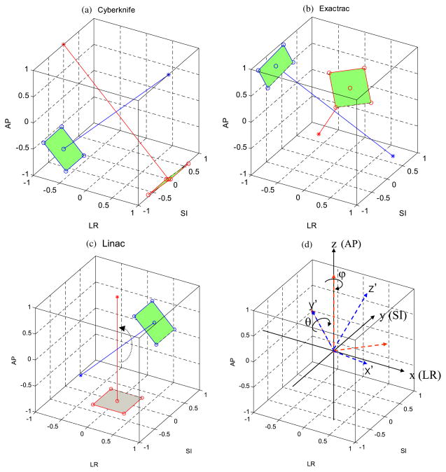
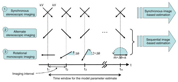
As representatives of the geometries and image acquisition methods among all available IGRT systems we chose three kV imaging systems: CyberKnife, ExacTrac and linac. Their geometries, image acquisition methods and the estimation approaches used in this study are summarized in table 1. Details of the geometries are illustrated in figure 1 and described in section 2.1.1. Details of the image acquisition methods and estimation methods are illustrated in figure 2 and explained in sections 2.1.3 and 2.1.4.
Table 1.
The geometries and image acquisition methods of commonly used IGRT systems studied here. The correlation-based 3D target position estimation methods applicable to each image acquisition method are shown in the last column (details are explained in sections 2.1.3 and 2.1.4).
| Commonly used IGRT systems | Geometry (figure 1) | Image acquisition method (figure 2) | Applicable 3D target position estimation methods |
|---|---|---|---|
| CyberKnife | Coplanar fixed dual kV imager | Synchronous stereoscopic imaging | Synchronous image-based estimation or Sequential image-based estimation |
| BrainLab ExacTrac | Non-coplanar fixed dual kV imager with 60° angular separation | Alternate stereoscopic imaging | Sequential image-based estimation |
| Elekta, Siemens, Varian linacs | Coplanar rotating single kV imager | Rotational monoscopic imaging | Sequential image-based estimation |
Figure 1.
The geometries of three kV imaging systems chosen in this study as representative of those commonly used for IGRT: (a) the CyberKnife system has a dual orthogonal kV imaging system in the coplanar plane, (b) the ExacTrac system has a dual kV imaging system in the non-coplanar plane with the angular separation of 60° and (c) linac for IGRT has a single gantry-mounted kV imaging system in the coplanar plane. (d) The rotation transforms from the patient coordinate system (x, y, z) to the imager coordinate system (x′, y′, z′). Rotation of ϕ around the z-axis and the following rotation of θ around the y-axis transforms the patient coordinates into the imager coordinate frame. Note that the source-to-axis distance and source-to-imager distance are not shown in the actual scale (for simplicity), but are included in the calculations.
Figure 2.
Image acquisition methods of commonly used IGRT systems and their estimation methods used in this study (see sections 2.1.3 and 2.1.4 for details). The directions of kV imaging and the angular range of the kV projection images are illustrated with continuous and black-dotted arrows, respectively. Here m is the number of data samples used to estimate the correlation model parameters which is equal to m images for the sequential (either alternate stereoscopic or rotational monoscopic) imaging, but 2m images for the synchronous stereoscopic imaging. Note that a respiratory signal, R(t), is also used in the sequential and synchronous image-based estimations.
For clarity, we will consistently use the following terms throughout the manuscript: (1) coplanar and non-coplanar describe the geometric arrangement of single or dual kV imagers, (2) the image acquisition methods are classified into three different categories: synchronous stereoscopic and sequential (either alternate stereoscopic or rotational monoscopic), and (3) the correlation-based 3D target position estimation methods are also classified into synchronous image-based estimation and sequential image-based estimation depending on the image acquisition methods. Synchronous image-based estimation is implemented in the Cyberknife Synchrony system and is used only for comparison in this study.
2.1. 3D target position estimation with internal–external correlation
2.1.1. Geometry
As shown in figure 1(d), two coordinate systems are used to describe the geometries of three kV imaging systems commonly used for IGRT. The patient coordinate system is defined such that each coordinate of a target position T(x, y, z) corresponds to the left–right (LR), superior–inferior (SI) and anterior–posterior (AP) direction, respectively. The imager coordinate system is defined such that the kV source and detector are located at z′ = SAD and z′ = SAD – SID, respectively. SAD and SID are the source-to-axis distance and the source-to-imager distance, respectively. The target position T(x, y, z) in the patient coordinates is transformed into a point T′(x′, y′, z′) of the imager coordinate system by sequentially applying a counter-clock wise rotation of ϕ around the z-axis and of θ around the y-axis to the patient coordinate system as follows:
| (1) |
Further applying a projection into the z′ direction of the imager coordinate system, the projected marker position (xp, yp ) on the imager plane is given by
| (2) |
Here, the perspective term is
| (3) |
2.1.2. Internal–external correlation
For an internal–external correlation model we applied the simple linear form, T̂(t) = aR(t) + b,
| (4) |
The simple linear correlation model in this study was chosen to see more clearly any existing effect of the geometries and image acquisition methods on the estimation, instead of making it intricate by adding more parameters with elaborate correlation models. However, the framework introduced here can be equally applied to the other linear correlation models, such as a curvilinear model (Seppenwoolde et al 2007) or a state augmented model (Ruan et al 2008).
Figure 2 illustrates three different image acquisition methods in commonly used IGRT systems and proposed position estimation strategies, which are described in detail in the following two sections.
2.1.3. Synchronous image-based estimation
The synchronous stereoscopic imaging systems provide synchronously measured kV image pairs, p(xp, yp; t) and , which reconstruct an instant 3D position T(x, y, z; t ) of a moving target by triangulation:
Given m measured target positions (x, y, z; {t1: tm}) and external monitor signals (R; {t1: tm}) up to the time point tm, the model parameters of the correlation can be determined in a least-squares sense as follows:
| (5) |
Since the correlation model is linear in the model parameters, the above minimization problem is converted into the following closed-form matrix equation:
| (6) |
With the model parameters given by solving the above equation, the estimated target positions (x̂, ŷ, ẑ; tm ≤ t < tm+1) will be determined from R(tm ≤ t < tm+1) using equation (4) until a next synchronous stereoscopic image-pair is acquired at time tm+1. Once the new target position is determined by triangulation with the image pair, the model parameters are updated by solving equation (6) with the most recently acquired consecutive m target positions and the external monitor signals. In such a way the model can adapt the temporal changes in the correlation. Since equation (6) is expressed in the patient coordinates, the synchronous image-based estimation is irrelevant to the geometry of the two imagers.
2.1.4. The sequential (either alternate stereoscopic or rotational monoscopic) image-based estimation
Unlike the synchronous image-based estimation solving the correlation model in each patient coordinate after triangulation, the sequential image-based estimation is designed to determine the model parameters directly using the projection positions in the imager coordinate because triangulation is not feasible for sequentially acquired kV images.
Given m projection data p(xp (θi, ϕi), yp (θi, ϕi); {t1: tm}) measured sequentially at various projection angles of (θi, ϕi ) at time ti, the least-squares estimation can be performed in the imager coordinates with equations (1) and (4):
| (7) |
Here, P (θi, ϕi ) represents the whole projection operation including the rotation transforms given in equation (1).
Similar to the synchronous image-based estimation expressed in equations (5) and (6), the above minimization problem is converted into the following matrix equation:
| (8) |
Equation (8) is to be solved to determine the model parameters (ax, bx, ay, by, az, bz), but apparently it is not solvable in its current form because the perspective term f (θi, ϕi ) is not determined until the equation has been solved.
However, it can be reasonably approximated in a solvable form as follows.
In general, target positions are not far from the isocenter, i.e. z′ ≪ SAD, and thus . At the first approximation, by ignoring the perspective projection (i.e. assuming parallel projection), equation (8) can be solvable with .
Once the approximate model parameters are determined, the perspective term f (θi, ϕi ) can be refined by solving equation (8) iteratively as follows (cf equation (3)):
| (9) |
where k is an iteration number and , and so on.
We tested the convergence and found the error converged to a minimum, quickly after a few iterations. Therefore, five iterations were used in the simulations being studied.
Until the next sequential image is given at time tm+1, the estimated target positions (x̂, ŷ, ẑ; tm ≤ t < tm+1) will be determined from R(tm ≤ t < tm+1) with the model parameters being computed at time tm. When a new projection position is measured at time tm+1, the model parameters are updated using the most recently acquired consecutive m projection positions and the external monitor signals.
2.2. Simulation
The sequential image-based estimation method was investigated in comparison with the synchronous image-based estimation approach by simulating a variety of scenarios according to the geometries and image acquisition methods of commonly used kV imaging systems. First of all, the synchronous and sequential image-based estimations were compared for the three kV imaging systems summarized in table 1. Next, feasible combinations of the geometries, the image acquisition methods and the estimation methods were further explored for the characterization of the sequential image-based estimation. Each scenario is explained in detail in the following subsections.
The dataset of total 160 abdominal/thoracic tumor trajectories and associated external respiratory monitor signals acquired with the CyberKnife system was used for simulations (Suh et al 2008). The tumor trajectories and external respiratory signals were recorded at 25 Hz. The initial 300 s duration of each trajectory was used for simulations with various imaging intervals of 0.2, 1, 2, 5 and 10 s.
Each time a new imaging data was supposed to be acquired the tumor position was projected into the imager planes for the sequential image-based estimation. On the other hand, the tumor position at the moment represented in the patient coordinates was directly used for the synchronous image-based estimation, instead of projection into the imager planes, triangulation and back-transformation into the patient coordinates. That is to say, perfect projection, triangulation and back transformation were assumed in the simulations ignoring any errors.
The most recent 20 consecutive imaging data (which were 3D target positions in the patient coordinates for the synchronous image-based estimation and 2D projected positions in the imager plane for the sequential image-based estimation) were used to determine the correlation model parameters with a moving window. Thus the time windows for the model parameter estimation were 4, 20, 40, 100 and 200 s for the imaging intervals of 0.2, 1, 2, 5 and 10 s, respectively. Note that the 20 3D target positions mean 40 images for the synchronous image-based estimation. Therefore, within the same time window the synchronous image-based estimation required twice as many images as the sequential image-based estimation.
The target position estimation started when the first 20 imaging data were acquired. In the sequential image-based estimation, with the first 20 images, the correlation model parameters were calculated iteratively, by applying equations (8) and (9) starting with the initial value of . After five iterations the computed model parameters were used for retrospective estimation of the target positions from the beginning up to the time point of the 20th image data acquisition. In the synchronous image-based estimation, they were done in the same way except that the model parameters were determined from equation (5) rather than equations (8) and (9).
Later on, whenever a new image was acquired at time tm, the model parameters were updated with the f (θi, ϕi ) value estimated using the previous correlation model parameters. These updated model parameters were used to estimate the target positions prospectively with R(tm ≤ t < tm+1), from the current imaging time tm to the next imaging time tm+1.
For simplicity, experimental errors associated with the finite pixel size of the imagers and other intrinsic factors (e.g. geometric calibration of the imagers) were not considered in the simulations. The number of samples for the model parameter estimation was fixed to m = 20, which may not be optimal, but is expected to be enough to determine the six model parameters and have little impact on the estimation accuracy. A more relevant factor is the time window because it will determine the response time of the model to the temporal change in the internal–external correlation.
The accuracy of the position estimation was quantified by the root-mean-square error (RMSE) for each trajectory as follows:
and similarly for the y and z components. Here, N is the total number of the estimated data points based on the external signals at 25 Hz for the 300 s duration including the initial 4–200 s with model building. The RMSE was calculated for each of the motion components (LR, SI and AP) and for the 3D vector.
2.2.1. Comparisons of estimation accuracy for three different imaging systems
Simulations of 3D target position estimation were performed with the 160 trajectories for the three representative kV imaging systems based on their geometries and image acquisition methods.
-
CyberKnife system: synchronous stereoscopic imaging with two orthogonal imagers in the coplanar geometry.
The CyberKnife imaging system consists of two kV sources at the ceiling and two corresponding flat panel detectors at the floor. The detectors are situated at approximately 140 cm from the isocenter and at a 45° angle to the kV beam central axes. The kV sources are located at 220 cm from the isocenter. Thus SAD and SID were set at 220 and 360 cm, respectively. The geometric configuration of each kV source corresponds to (θ1 = 45°, ϕ1 = 0°) and (θ2 = −45°, ϕ2 = 0°) in equation (1), respectively. Their orthogonal beam axes form a coplanar plane. However, since the experimental uncertainties were not taken into account for the simulations, each time a new synchronous kV image pair was supposed to be acquired, the true target position in the patient coordinates was directly used instead of projection and triangulation. The synchronous image-based estimation was applied to compute the model parameters with the most recent 20 target positions. Note that in the study, the CyberKnife geometry was used to model both synchronous stereoscopic and alternate stereoscopic image-based estimation.
-
ExacTrac system: alternate stereoscopic imaging between two imagers with 60° separation in the non-coplanar geometry.
The ExacTrac system consists of two kV sources at the floor and two corresponding flat panel detectors at the ceiling. Their beam axes form a non-coplanar plane with 60° angular separation. A projected marker position p was acquired alternately between the two kV imagers configured at (θ1 = 135°, ϕ1 = 45°) and (θ2 = 135°, ϕ2 = 135°) in equation (1), with SAD = 230 cm and SID = 360 cm. The sequential image-based estimation was applied to determine and update the correlation parameters with the most recent 20 projection positions.
-
Linacs: rotational monoscopic imaging with a single imager rotating with the gantry in the coplanar geometry.
Linacs for IGRT are equipped with a single kV imaging system rotating with the gantry. Its rotating beam axes form a coplanar plane. Unlike the real systems, the imager was kept rotating over the 300 s tracking interval with unlimited speed. The 20 consecutive projected positions p were acquired at ϕ = 0° and θi = (π · i)/m, i = 1, …, m, so that the 20 projections covered 180° angular range evenly, to make the mean angular separation 90°. In reality linacs have the upper rotating speed limit of 6° s−1. When this limitation is applied, the 20 projections will cover 24, 120, 240, 600 and 1200° for imaging intervals of 0.2, 1, 2, 5 and 10 s, respectively. However, since this inter-relationship between the imaging interval and the angular range is specific only to the linacs’ imaging configuration, the angular range was fixed to cover 180° in order to closely investigate the influence of the estimation method itself (sequential versus synchronous) without any influence from the variation of the angular range. The influence from the angular range was separately investigated in section 3.4. SAD and SID were set at 100 and 150 cm, respectively. The sequential image-based estimation was also applied to this case.
2.2.2. Impact of the estimation method: synchronous versus sequential image-based estimation for the synchronous stereoscopic imaging
Note that the sequential image-based estimation can also be applicable to the synchronous stereoscopic imaging by bypassing the triangulation procedure. Therefore applying both estimation methods to the same synchronous stereoscopic imaging data is an interesting comparison. To test any loss of estimation accuracy of the sequential image-based estimation due to abandoning the privileged synchrony information between images, the approach was applied to the synchronous stereoscopic imaging in the CyberKnife’s coplanar and the ExacTrac’s non-coplanar geometry, and its estimation errors were compared with the estimation errors of the synchronous image-based estimation.
2.2.3. Impact of the geometry
alternate stereoscopic imaging in coplanar versus non-coplanar geometry. The synchronous stereoscopic imaging is irrelevant to the geometries, either coplanar or non-coplanar. In contrast, since the sequential image-based estimation may be affected by the geometries, it was tested with the alternate stereoscopic imaging in the CyberKnife’s coplanar and ExacTrac’s non-coplanar geometries at various imaging intervals.
Another simple question was the dependence of the sequential image-based estimation on SAD. For this purpose, the sequential image-based estimation for the rotational monoscopic imaging at the 1 s interval was simulated with SAD = 100, 150, 200 and 250 cm.
2.2.4. Impact of the angular range of the rotational monoscopic imaging on the sequential image-based estimation
For the rotational monoscopic imaging in the overall comparison in section 2.2.1, the angular range to estimate the model parameters was set at 180° such that the images had a 90° angular separation on average, which would be comparable to the other imaging geometries: 90° separation for the CyberKnife system and 60° separation for the ExacTrac system. One interesting question was how the angular range for the parameter estimation impacted the accuracy of the sequential image-based estimation. Thus simulations were performed with the sequential image-based estimation for the rotational monoscopic imaging in the linacs’ coplanar geometry as a function of the angular span.
3. Results and discussion
3.1. Comparisons of estimation accuracy for the three different imaging systems
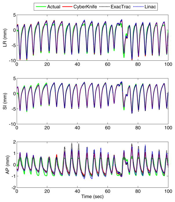
Typical tumor motion and the corresponding motion estimation traces for the Cyberknife, ExacTrac and linac geometries are shown in figure 3. The estimated traces are all very similar, even in places where they differ from the tumor motion trace. This similarity means that the limiting factor in this case is not the IGRT system geometry but limitations in the model itself, or the underlying unaccounted-for variations in the intrinsic internal–external correlation.
Figure 3.
Typical tumor motion estimation results for the CyberKnife geometry (synchronous image-based method), ExacTrac and linac geometries (sequential image-based method). Top: left–right; middle: superior–inferior; bottom: anterior–posterior. The estimation results are similar for all methods. The kV imaging frequency was one image per second.
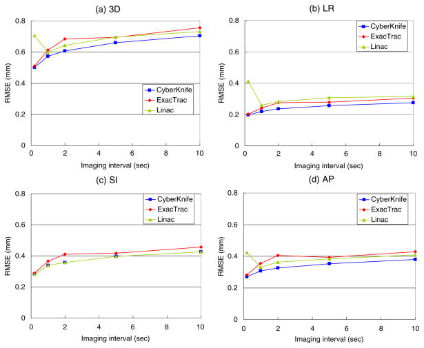
As shown in figure 4(a), both sequential and synchronous estimation methods can achieve mean 3D errors less than 1 mm for all three imaging systems at all imaging intervals. When the imaging interval approaches zero the estimation error approaches the minimum of ~0.5 mm, which is attributed to the nature of the internal–external correlation that cannot be fully explained by a simple linear function. A longer imaging interval increases the estimation error gradually because the wider time window for the model parameters estimation slows down the model adaptation to the temporal change in the correlation. This response delay of the model adaptation adds ~0.2 mm on the 3D estimation error up to the 10 s imaging interval with the 200 s time window. It suggests that the internal–external correlation does not change rapidly for most cases. In fact, a recent clinical study based on the Synchrony system showed that accurate tracking was achievable even though the imaging intervals were larger than 1 min (Hoogeman et al 2009). However, for more definitive conclusion on this fact, further comprehensive study is necessary.
Figure 4.
Mean estimation RMSE of the estimation method applied to the 160 traces for the three IGRT geometries. The synchronous image-based estimation was applied to the synchronous stereoscopic imaging in the coplanar geometry (CyberKnife), while the sequential image-based estimation was applied to the alternate stereoscopic imaging in the non-coplanar geometry (ExacTrac) and the rotational monoscopic imaging in the coplanar geometry (linac). Note that these results are not necessarily representative of clinically available system performance, but they represent the potential capability of the systems using the models described.
The CyberKnife system shows the best accuracy over all the imaging intervals. Note that the CyberKnife system has double the amount of kV images compared to the others, because the synchronous image-pair is acquired at each imaging interval. Better accuracies of the CyberKnife system in the LR and AP directions, shown in figures 4(b) and (d), are attributed to this fact because it has double the amount of spatial information in both directions. In contrast, there is no accuracy improvement of the CyberKnife system in the SI direction compared to the linacs’ imaging system, which has the same coplanar geometry, as two images acquired at the same time give the identical SI position. In figure 4(c), the non-coplanar alternate stereoscopic imaging of the ExacTrac system shows lower accuracy in the SI direction compared to the coplanar rotational monoscopic imaging of Linacs, because its non-coplanar geometry projects the SI and LR components onto yp, as shown in the equation (1), while the coplanar geometry of the Linacs estimates the SI component from yp separately.
One interesting feature of the rotational monoscopic imaging is that the estimation error rebounds at the 0.2 s imaging interval. While the alternate stereoscopic imaging has a 60° angular separation between subsequent images, the rotational monoscopic imaging only has 9° angular separation between subsequent images (180°/20 images). This may not be enough to discriminate small displacement of the target during the short interval of 0.2 s. This fact was confirmed with another simulation in which the angular separation between rotational monoscopic images was 60°. The results (not shown here) did not show an accuracy reduction for 0.2 s imaging intervals. It was also confirmed that the accuracy could be improved by increasing the modeling time window, yet not significantly because the wider window reduced the prompt model adaptation to the temporal change in the correlation. Anyhow, the angular range of 180° during 20 s is impossible considering the speed limit of linacs and such a fast imaging like 0.2 s is unnecessary for the application of the ‘internal–external’ correlation-based target position estimation. However, as it revealed in section 3.4, the angular range larger than 120° did not affect the estimation accuracy and thus the result of the simulation ignoring the rotating speed limit of linacs might remain valid except the imaging interval of 0.2 s.
3.2. Impact of the estimation method: synchronous versus sequential image-based estimation when acquiring synchronous images
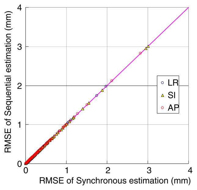
The sequential image-based estimation (equation (7)) applied to the synchronous stereoscopic acquisition method reveals the same accuracy as the synchronous image-based estimation (equation (5)) over all the image intervals. As an example, the estimation results of the 1 s imaging interval in the non-coplanar geometry are shown in figure 5.
Figure 5.
Performance comparison of synchronous versus sequential image-based estimation applied to the same synchronous stereoscopic imaging data (1 s interval) in the non-coplanar geometry. Each point represents pair-wise estimation errors of synchronous versus sequential image-based estimation for the 160 trajectories.
The estimation results in the coplanar geometry are also the same, demonstrating no loss of estimation accuracy due to bypassing the triangulation procedure. It means that, at least for the purpose of estimating the internal–external correlation model parameters, the synchronous information on images does not play any role. The practical significances of this fact are: (1) the current sequential form of the ExacTrac system is sufficient for the correlation-based target tracking and thus updating the synchronous stereoscopic imaging system is not necessary, and (2) the CyberKnife system can use the sequential image-based estimation with alternate stereoscopic imaging, if necessary, without loss of accuracy. This result implies that the sequential method is equally accurate to the synchronous method and applicable to other IGRT systems, whereas the synchronous method is not.
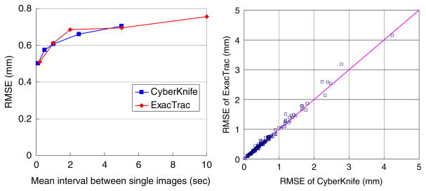
Indeed, the synchronous stereoscopic imaging may not be optimal compared with the alternate stereoscopic imaging if imaging dose to the patient is considered. Acquiring each image alternately at a certain imaging interval may be more accurate than acquiring each synchronous image-pair at a twice longer interval because the former would collect more information on the temporal variation in the internal–external correlation. Figure 6 is a re-plot of the same data shown in figure 4(a) by rescaling the imaging interval of the synchronous stereoscopic imaging (CyberKnife) such that the number of images are the same as that of the alternate stereoscopic imaging (ExacTrac). However, there is no noticeable accuracy difference between the two approaches. As mentioned earlier, the accuracy of the 3D position estimation was deteriorated less than 0.2 mm by increasing the imaging interval from 0.2 to 10 s probably due to the slow change of the internal–external correlation over time. In other words, the 0.2 mm gain of the tracking accuracy cannot be justified at the cost of 20 times more imaging dose to the patient within the imaging interval studied. In addition, all the three image acquisition methods provide already sub-mm accuracy with only subtle difference, thus there is no method superior to another.
Figure 6.
(a) Re-plot of the 3D mean RMSE from figure 4(a) by rescaling the imaging interval of the synchronous stereoscopic imaging (CyberKnife) such that the number of images are the same as that of the alternate stereoscopic imaging (ExacTrac). (b) Pair-wise accuracy comparison of CyberKnife versus ExacTrac for the 1 s mean imaging interval in (a), for the 160 dataset.
3.3. Impact of the geometry: alternate stereoscopic imaging in the coplanar versus non-coplanar geometry
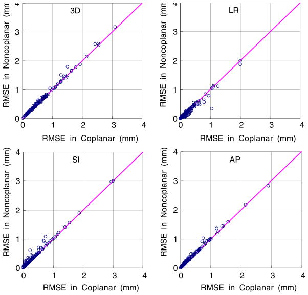
The sequential image-based estimation for the alternate stereoscopic imaging in the coplanar and non-coplanar geometries was simulated at various imaging intervals. Figure 7 shows the coplanar versus non-coplanar pair-wise comparisons of the estimation errors over the 160 dataset for the 1 s imaging interval. The SI component was always resolved in the coplanar geometry, but not in the non-coplanar geometry. Thus the estimation of the SI component is more accurate in the coplanar geometry than in the non-coplanar geometry. On the other hand, the estimation of the LR(x) component would be more accurate in the non-coplanar geometry since yp also shares the LR information. Likewise, the AP(z) component is more accurate in the coplanar geometry because it is estimated from xp = cosθ · Tx + sinθ · Tz compared to the non-coplanar geometry, where xp is the combination of all three patient coordinates. Overall the coplanar geometry is more favorable to the sequential image-based estimation because the AP and SI, which are known as relatively large components of respiratory motion, can be estimated more accurately, resulting in better accuracy. However the accuracy improvement is less than 0.01 mm in the overall 3D RMSE.
Figure 7.
The sequential image-based estimation for the alternate stereoscopic imaging in the coplanar versus non-coplanar geometry at the 1 s interval.
As for the SAD dependence of the estimation accuracy in the sequential image-based estimation, larger SAD is expected to be more favorable to the sequential image-based estimation because in the perspective term it becomes closer to parallel projection and results in smaller error in equation (8). As SAD was increased from 100 to 250 cm, the average RMSE over the 160 trajectories was improved by only 0.02% for the rotational monoscopic imaging at the 1 s interval.
3.4. Impact of the angular range of the rotational monoscopic imaging on the sequential image-based estimation
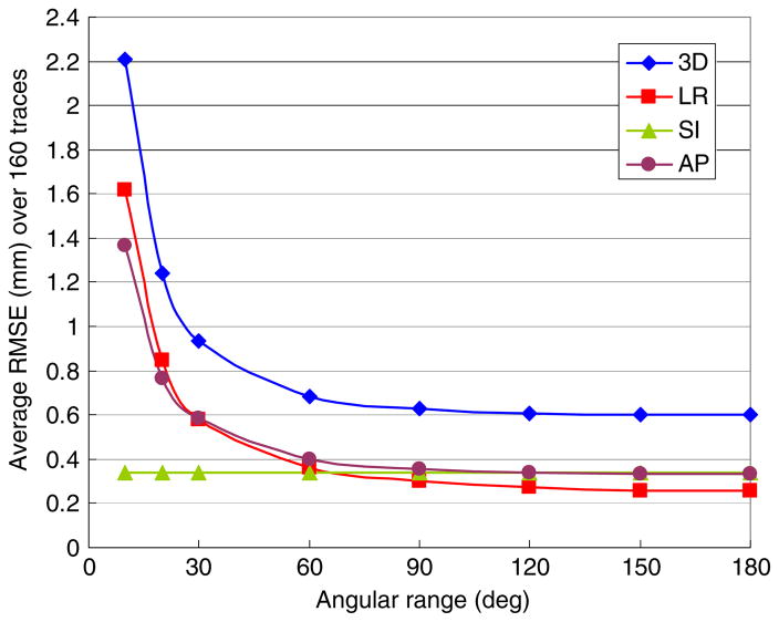
The effect of the angular span on the estimation accuracy was investigated by simulating the sequential image-based estimation for the rotational monoscopic imaging in the coplanar geometry as a function of the angular span. The results are shown in figure 8. As the angular span narrowed from 180° to 120°, there was little loss of estimation accuracy. Note that an angular span of 120° corresponds to a 6° angular separation between consecutive images and an average angular separation of images of 60°. The mean 3D estimation error increased around 5% and 14% at 90° and 60° angular span, respectively. After that, it increased rapidly with further narrowing of the angular span. As expected, the estimation error in the resolved SI direction was irrelevant to the angular span. The errors in both the LR and AP directions increased together because of rotational imaging.
Figure 8.
Average RMSE of the 160 trajectories with the rotational monoscopic imaging at 1 s interval as a function of the angular range to estimate the model parameters of the sequential image-based estimation.
In the limit when the angular span narrowed down to zero, the sequential image-based estimation became singular. To make it solvable further constraint on the correlation model should be imposed. Aiming at such a truly monoscopic imaging configuration that happens with static beam delivery, we presented a similar estimation method in our previous work (Cho et al 2008). In the study, the correlation was modeled in the imager plane as , and the further constraint in the unresolved motion was imposed as ẑ′ = azxp + bzyp + cz with a priori 3D target motion information. Since the correlation model itself is affixed to the imager coordinates, it should be reset and re-built whenever the beam direction is changed. If reformulated in the patient coordinates with an inter-dimensional relationship, x̂ = ay + bz + c, this problem can be merged into the current framework of the sequential image-based estimation. Moreover, the parameters of the inter-dimensional relationship, i.e. a priori 3D target motion information, can be obtained naturally with the rotational monoscopic imaging.
A similar approach employing an inter-dimensional correlation model in the imager coordinates was also introduced for kV/MV image-based tracking without an external respiratory monitor (Wiersma et al 2009). The same framework can also be applied to this approach, with the inter-dimensional correlation expressed in the patient coordinates such as x = ay + bz + c. It would eliminate the need for rebuilding the model parameters with changes in the beam direction and provide a natural way to build the correlation for rotational imaging. Such inter-dimensional correlation was also explored with a statistical model for respiratory motion estimation (Poulsen et al 2010) and prostate motion estimation (Poulsen et al 2008, 2009).
The internal–external correlation model is aimed at estimating respiratory tumor motion using external breathing monitors, and thus is not feasible for tumor motion irrelevant to breathing (such as prostate). On the other hand, position estimation methods using x-ray imaging alone require a fairly fast imaging frequency to obtain real-time estimation of a moving tumor. Thus both methods can be used complementarily depending on the purpose of the applications, treatment sites and clinical needs.
Finally, though the study here focuses on kV imaging due to improved contrast and noninterference of MLC leaves, without loss of generality the method could be applied to MV imaging systems alone or in combination with kV imaging.
4. Conclusions
A generalized 3D target position estimation method based on internal–external correlation has been developed and investigated. The key idea of the sequential image-based estimation is (1) recasting the least-squares formula for estimating the correlation model parameters from expressions in the patient coordinates to expressions in the projection coordinates, and (2) further reformulation of the model in a quickly-converging iterative form supported by the fact that the perspective projection in the range of tumor motion is nearly a parallel projection. The method was tested in a large dataset through simulations for a variety of common clinical IGRT configurations: synchronous stereoscopic imaging, alternate stereoscopic imaging, and rotational monoscopic imaging. The accuracy of the method was similar for all of the clinical configurations. The estimation accuracy showed mean 3D RMSE less than 1 mm and had a weak dependence on imaging frequency. Most importantly, the estimation accuracy of the sequential image-based estimation was the same as the synchronous stereoscopic image-based estimation for the same synchronously acquired stereoscopic images. The practical significance of this fact is that with the sequential image-based estimation the alternate stereoscopic and rotational monoscopic imaging systems can achieve the same accuracy for the correlation-based 3D target position estimation as the synchronous stereoscopic imaging systems for the same imaging dose to the patient. The sequential image-based estimation method is applicable to all common IGRT systems and could overcome some limitations of synchronous stereoscopic imaging systems, such as when the linac obscures one of the x-ray systems.
Acknowledgments
This work was partially supported by NIH/NCI grant R01CA93626. The authors wish to thank James Parris for useful insights and clarification of this method, and Libby Roberts for carefully editing the text.
References
- Berbeco RI, Jiang SB, Sharp GC, Chen GTY, Mostafavi H, Shirato H. Integrated radiotherapy imaging system (IRIS): design considerations of tumour tracking with linac gantry-mounted diagnostic x-ray systems with flat-panel detectors. Phys Med Biol. 2004;49:243–55. doi: 10.1088/0031-9155/49/2/005. [DOI] [PubMed] [Google Scholar]
- Cho BC, Suh YL, Dieterich S, Keall PJ. A monoscopic method for real-time tumour tracking using combined occasional x-ray imaging and continuous respiratory monitoring. Phys Med Biol. 2008;53:2837–55. doi: 10.1088/0031-9155/53/11/006. [DOI] [PubMed] [Google Scholar]
- D’Souza WD, McAvoy TJ. An analysis of the treatment couch and control system dynamics for respiration-induced motion compensation. Med Phys. 2006;33:4701–9. doi: 10.1118/1.2372218. [DOI] [PubMed] [Google Scholar]
- Hoogeman M, Prevost JB, Nuyttens J, Poll J, Levendag P, Heijmen B. Clinical accuracy of the respiratory tumor tracking system of the Cyberknife: assessment by analysis of log files. Int J Radiat Oncol Biol Phys. 2009;74:297–303. doi: 10.1016/j.ijrobp.2008.12.041. [DOI] [PubMed] [Google Scholar]
- ICRU. ICRU Report. Vol. 62. Bethesda, MD: ICRU; 1999. Prescribing, recording, and reporting photon beam therapy (supplement to ICRU Report 50) [Google Scholar]
- Jin JY, Yin FF, Tenn SE, Medin PM, Solberg TD. Use of the BrainLAB ExacTrac X-ray 6D system in image-guided radiotherapy. Med Dosim. 2008;33:124–34. doi: 10.1016/j.meddos.2008.02.005. [DOI] [PubMed] [Google Scholar]
- Keall PJ, Kini VR, Vedam SS, Mohan R. Motion adaptive x-ray therapy: a feasibility study. Phys Med Biol. 2001;46:1–10. doi: 10.1088/0031-9155/46/1/301. [DOI] [PubMed] [Google Scholar]
- Kubo HD, Hill BC. Respiration gated radiotherapy treatment: a technical study. Phys Med Biol. 1996;41:83–91. doi: 10.1088/0031-9155/41/1/007. [DOI] [PubMed] [Google Scholar]
- Murphy MJ. Tracking moving organs in real time. Semin Radiat Oncol. 2004;14:91–100. doi: 10.1053/j.semradonc.2003.10.005. [DOI] [PubMed] [Google Scholar]
- Ohara K, Okumura T, Akisada M, Inada T, Mori T, Yokota H, Calaguas MJB. Irradiation synchronized with respiration gate. Int J Radiat Oncol Biol Phys. 1989;17:853–7. doi: 10.1016/0360-3016(89)90078-3. [DOI] [PubMed] [Google Scholar]
- Ozhasoglu C, Murphy MJ. Issues in respiratory motion compensation during external-beam radiotherapy. Int J Radiat Oncol Biol Phys. 2002;52:1389–99. doi: 10.1016/s0360-3016(01)02789-4. [DOI] [PubMed] [Google Scholar]
- Poulsen PR, Cho B, Keall PJ. Real-time prostate trajectory estimation with a single imager in arc radiotherapy: a simulation study. Phys Med Biol. 2009;54:4019–35. doi: 10.1088/0031-9155/54/13/005. [DOI] [PubMed] [Google Scholar]
- Poulsen PR, Cho B, Langen K, Kupelian P, Keall PJ. Three-dimensional prostate position estimation with a single x-ray imager utilizing the spatial probability density. Phys Med Biol. 2008;53:4331–53. doi: 10.1088/0031-9155/53/16/008. [DOI] [PubMed] [Google Scholar]
- Poulsen PR, Cho B, Ruan D, Sawant A, Keall PJ. Dynamic MLC tracking of respiratory target motion based on a single kilovoltage imager during arc radiotherapy. Int J Radiat Oncol Biol Phys. 2010;77:600–7. doi: 10.1016/j.ijrobp.2009.08.030. [DOI] [PubMed] [Google Scholar]
- Ruan D, Fessler JA, Balter JM, Berbeco RI, Nishioka S, Shirato H. Inference of hysteretic respiratory tumor motion from external surrogates: a state augmentation approach. Phys Med Biol. 2008;53:2923–36. doi: 10.1088/0031-9155/53/11/011. [DOI] [PubMed] [Google Scholar]
- Sawant A, Smith RL, Venkat RB, Santanam L, Cho BC, Poulsen P, Cattell H, Newell LJ, Parikh P, Keall PJ. Toward submillimeter accuracy in the management of intrafraction motion: the integration of real-time internal position monitoring and multileaf collimator target tracking. Int J Radiat Oncol Biol Phys. 2009;74:575–82. doi: 10.1016/j.ijrobp.2008.12.057. [DOI] [PubMed] [Google Scholar]
- Sawant A, Venkat R, Srivastava V, Carlson D, Povzner S, Cattell H, Keall P. Management of three-dimensional intrafraction motion through real-time DMLC tracking. Med Phys. 2008;35:2050–61. doi: 10.1118/1.2905355. [DOI] [PMC free article] [PubMed] [Google Scholar]
- Schweikard A, Shiomi H, Adler J. Respiration tracking in radiosurgery. Med Phys. 2004;31:2738–41. doi: 10.1118/1.1774132. [DOI] [PubMed] [Google Scholar]
- Seppenwoolde Y, Berbeco RI, Nishioka S, Shirato H, Heijmen B. Accuracy of tumor motion compensation algorithm from a robotic respiratory tracking system: a simulation study. Med Phys. 2007;34:2774–84. doi: 10.1118/1.2739811. [DOI] [PubMed] [Google Scholar]
- Shirato H, et al. Four-dimensional treatment planning and fluoroscopic real-time tumor tracking radiotherapy for moving tumor. Int J Radiat Oncol Biol Phys. 2000;48:435–42. doi: 10.1016/s0360-3016(00)00625-8. [DOI] [PubMed] [Google Scholar]
- Suh Y, Dieterich S, Cho B, Keall PJ. An analysis of thoracic and abdominal tumour motion for stereotactic body radiotherapy patients. Phys Med Biol. 2008;53:3623–40. doi: 10.1088/0031-9155/53/13/016. [DOI] [PubMed] [Google Scholar]
- Wiersma RD, Riaz N, Dieterich S, Suh YL, Xing L. Use of MV and kV imager correlation for maintaining continuous real-time 3D internal marker tracking during beam interruptions. Phys Med Biol. 2009;54:89–103. doi: 10.1088/0031-9155/54/1/006. [DOI] [PubMed] [Google Scholar]


