

Abstract
We describe the self-assembly of a DNA crystal that contains two tensegrity triangle molecules per asymmetric unit. We have used X-ray crystallography to determine its crystal structure. In addition, we have demonstrated control over the colors of the crystals by attaching either Cy3 dye (pink) or Cy5 dye (blue-green) to the components of the crystal, yielding crystals of corresponding colors. Attaching the pair of dyes to the pair of molecules yields a purple crystal.
DNA is well-known as the genetic material of all living organisms.1 However, it has been proposed and shown that synthetic branched DNA molecules can be used to control the structure of matter on the nanometer scale.2 Recently, we have reported the X-ray crystal structure of a designed macroscopic self-assembled 3D crystal based on a robust motif.3 That crystal contained a single molecular species, a tensegrity triangle,4 per unit cell; the molecule’s self-assembly into a crystal was programmed through the sticky-ends at the end of each DNA double helix. One of the strengths of using the chemical information contained in sticky ends to program self-assembly is that one ought to be able to control the number of species contained within the unit cell. This capability has been demonstrated in very small (~1–10 microns) two dimensional crystals, but macroscopic 3D crystals provide the most interesting case. Here, we report the X-ray crystal structure of a DNA crystal containing two different molecules that have been programmed to crystallize in an alternating pattern, according to the design. In addition, we demonstrate that we can control the colors of the crystals by covalent attachment of dyes to the two different molecules.
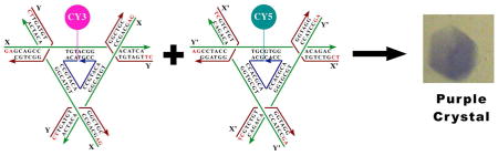
The sequences of the molecules used are shown in Figure 1. The strands in the A molecule are not the same as those in the B molecule. As done previously,3 we have symmetrized each molecule 3-fold by using the same sticky ends on each domain. In addition, the red strands are the same within a given molecule, as are the green strands; the central blue strand is also a three-fold repeating sequence. The sticky ends on the A molecule are GA and CT, which are not complementary. Likewise, the sticky ends on the B molecule are AG and TC, also not complementary. However, the sticky ends on the B-molecules are complementary to the A-molecules, so the two molecules will alternate throughout the crystal lattice.
Figure 1.

The sequences of the two different tensegrity triangles that have been combined into a single crystal. There are three unique strands in each triangle, the red, the green and the blue. The sticky ends are drawn with red letters, and they are designated as X, Y, X′ and Y′. Arrowheads indicate 3′ ends of strands.
The unit cell volume of this crystal is within 4.5% of exactly twice the volume of the crystal3 containing only a single molecule per unit cell (Table 1). Figure 2a shows the nearest and second-nearest neighbors of a single tensegrity triangle, drawn in green. This stereoscopic representation illustrates the molecular structures of the tensegrity triangles. Note that all six nearest neighbors shown are of the other species, drawn in red, and the second-nearest are again green. Thus, there is an alternating arrangement within the crystal. This alternation is shown dramatically in Figure 2b, which is another stereoscopic image illustrating eight of the molecules in a space-filling representation. Overall, the eight triangles form a rhombohedral arrangement. Whereas previously3 the molecules flanking each corner of the rhombohedron were equivalent, now they form two intersecting tetrahedra of different species, as seen from the red and green color coding. The two different tetrahedra are seen to form an alternating arrangement, occupying the opposite ends of each edge and body diagonal of the rhombohedron.
Table 1.
Data collection and processing:
| Crystal design | Single triangle (Nature 2009 461, 74–77.) | Two triangles (A+B)1 (RCSB code 3NAO) |
| Unit cell (R3) | a = 69.22 Å, α = 101.44° (a = 87.65 Å, α = 75.37°)2 | a = 86.36 Å, α = 75.16° (a = 68.31 Å, α = 101.59°)3 |
| Volume (Å3) of unit cell/ASU4 | 308708/102903 | 589184/196395 |
| Content of unit cell/ASU | One triangle/1/3 triangle | Two triangles (A+B)/1/3 each of triangles A and B |
| Resolution (Å) | 17.3-4.01 | 35.0-5.0 |
| Wavelength (Å) | 1.0 | 0.984 |
| Redundancy5 | 7.3(6.0) | 9.0(4.5) |
| Completeness (%)5 | 96.1(100.0) | 97.2(87.1) |
| Rmerge5 | 0.067(0.594) | 0.056(0.461) |
| I/σ | 10.9 | 15.2 |
| Refinement statistics: | ||
| Resolution (Å) | 35.0-5.0 | |
| Rwork/Rfree | 0.1821/0.2393 | |
| Number of nucleic acid atoms | 1710 | |
| Number of non-nucleic acid atoms | 0 | |
| R.m.s.d. of angle and bond | 1.221°/0.0052Å | |
Data collected at beamline X6A at NSLS;
This unit cell of double triangles design is derived from the unit cell of single triangle design;
This unit cell of single triangle design is derived from the unit cell of double triangles design;
ASU = asymmetric unit;
Numbers in parenthesis represent values for the highest resolution bin
Figure 2.

Stereoscopic representations of the arrangement of the two different tensegrity triangles in the crystal. (a) The two nearest neighbors of a molecule. The molecules are shown in a conventional line drawing. The central molecule in green is surrounded by six different red molecules, two in each direction of lattice propagation, one in front and one behind. These are in turn flanked by their green neighbors in the same directions. (b) A space-filling representation of the rhombohedron formed by eight of the molecules within the lattice. Intersecting red and green tetrahedra are seen to form the rhombohedron. There is a cavity at the center of the rhombohedron.
The mixed arrangement can also affect the properties of the crystal. In Figure 3, we show nine different images of the crystals to illustrate how a designed self-assembled crystal enables us to control its color by adding Cy3 and Cy5 dyes during synthesis as phosphoramidites (Glen Research). The central panel shows a crystal to which no dyes have been attached. In all the other cases, one or more molecules of dye have been attached to the 5′ end of one or both of the central strands (blue in Figure 1) of the triangles. The unit cell dimensions of the three crystal types are within one Å of each other.
Figure 3.

Covalent attachment of dyes to the independent molecules in the crystal. The way in which the components of each crystal drop were prepared is indicated above each image of crystals. In the top row, from left to right, Cy3 has been attached to the A molecule, to both molecules, and to the B molecule. Crystals in all three drops are pink. The bottom row has a similar arrangement of molecules to which Cy5 has been attached, left, A, center, both, and right, B. Crystals in all three drops are blue-green. The center row contains drops with both arrangements of molecules containing both dyes, Cy3 on molecule A and Cy5 on molecule B in the drop on the left, and the opposite arrangement on the right. Both drops are purple in color. The center drop contains a control whose molecules have neither dye attached to them.
Figure 3 illustrates the level of control that we have achieved over the coloration properties of the crystal. The top row crystals show the characteristic pink color of Cy3 when it is attached to either molecule A, molecule B or both. Similarly, the bottom row crystals show the characteristic blue-green color of Cy5 when it is attached to molecule A, molecule B or both. The crystal on the ends of the middle row show the purple color that arises when the two dyes are mixed stoichiometrically, in either order, Cy3 on molecule A and Cy5 on molecule B or Cy5 on molecule A an Cy5 on molecule B. No pink or blue crystals appear when both dyes are present, and all crystals in every setup are identical, demonstrating that the sticky ends of both independent molecules must be present to obtain crystals, and that they do not self-pair.
The dyes have been attached to a unique position within the structure, a position that winds up being 3-fold averaged within the crystal lattice. Consequently, the electron density corresponding to the dyes is 3-fold averaged with solvent areas so only 33% of electron density due to the dye would appear. The 3-fold averaging, the tethering of the dyes on a 6-bond linker, and the resolution of the crystals (5 Å) all combine to make the electron density corresponding to the dyes undetectable in the crystallographic analysis reported here. Of 855 atoms in each molecule, 802 are identical and pseudo-centering is evident in the diffraction pattern. Nevertheless, even at this resolution, reversing the two molecules leads to significantly worse agreement (see supplementary information).
We have demonstrated that it is possible use sticky-end directed self-assembly to control the contents of a macromolecular 3D crystal. The only intermolecular interactions between triangle molecules within the crystal are those we have programmed with sticky ends. We have deliberately designed the intermolecular crystalline contacts so that there are two different molecules in the asymmetric unit of the crystal, and they alternate through the lattice. We have used X-ray crystallography molecular replacement techniques to determine the crystal structure of the pair of molecules. In addition, we have shown that the covalent attachment of dye molecules to the DNA units results in different colors for the crystals. This work establishes the feasibility of using specific designs to construct specific arrangements of macromolecular crystalline species in three dimensions.
No pink or blue crystals appear when both dyes are present, demonstrating that the sticky ends of both independent molecules must be present to obtain crystals, and that they cannot self-pair.
Supplementary Material
Acknowledgments
This research was carried out in part at X6A beam line, funded by the NIGMS, National Institute of Health under agreement Y1 GM-0080.-03. The National Synchrotron Light Source, Brookhaven National Laboratory is supported by the U.S. Department of Energy under contract No. DE-AC02-98CH10886. We appreciate support provided by Drs. M. Allaire, V. Stojanoff & J. Jakoncic. We acknowledge support by grant GM-29554 from NIGMS, grants CTS-0608889 and CCF-0726378 from the NSF, grant W911FF-08-C-0057 from ARO, via Pegasus Corporation, MURI W911NF-07-1-0439 from ARO, grants N000140910181 and N000140911118 from ONR and a grant from the W.M. Keck Foundation to N.C.S.
Footnotes
Supporting Information. Full experimental details including: Crystallization protocols, crystallographic processing and the syntheses of dye-labeled oligonucleotides and dye structures.
References
- 1.Watson JD, Crick FHC. Nature. 1953;171:737–738. doi: 10.1038/171737a0. [DOI] [PubMed] [Google Scholar]
- 2.Seeman NC. J Theor Biol. 1982;99:237–247. doi: 10.1016/0022-5193(82)90002-9. [DOI] [PubMed] [Google Scholar]; Seeman NC. Ann Rev Biochem. 2010;79:65–87. doi: 10.1146/annurev-biochem-060308-102244. [DOI] [PMC free article] [PubMed] [Google Scholar]
- 3.Zheng J, Birktoft JJ, Chen Y, Wang T, Sha R, Constantinou PE, Ginell SL, Mao C, Seeman NC. Nature. 2009;461:74–77. doi: 10.1038/nature08274. [DOI] [PMC free article] [PubMed] [Google Scholar]
- 4.Liu D, Wang W, Deng Z, Walulu R, Mao C. J Am Chem Soc. 2004;126:2324–2325. doi: 10.1021/ja031754r. [DOI] [PubMed] [Google Scholar]
Associated Data
This section collects any data citations, data availability statements, or supplementary materials included in this article.