

Abstract
A magnetic resonance (MR) compatible positron emission tomography (PET) insert has been developed in our laboratory for simultaneous small animal PET/MR imaging. This system is based on lutetium oxyorthosilicate (LSO) scintillator arrays with position-sensitive avalanche photodiode (PSAPD) photodetectors. The PET performance of this insert has been measured. The average reconstructed image spatial resolution was 1.51 mm. The sensitivity at the center of the field of view (CFOV) was 0.35%, which is comparable to the simulation predictions of 0.40%. The average photopeak energy resolution was 25%. The scatter fraction inside the MRI scanner with a line source was 12% (with a mouse-sized phantom and standard 35 mm Bruker 1H RF coil), 7% (with RF coil only) and 5% (without phantom or RF coil) for an energy window of 350–650 keV. The front-end electronics had a dead time of 390 ns, and a trigger extension dead time of 7.32 μs that degraded counting rate performance for injected doses above ~0.75 mCi (28 MBq). The peak noise-equivalent count rate (NECR) of 1.27 kcps was achieved at 290 μCi (10.7 MBq). The system showed good imaging performance inside a 7-T animal MRI system; however improvements in data acquisition electronics and reduction of the coincidence timing window are needed to realize improved NECR performance.
Index Terms: Avalanche photodiodes, positron emission tomography (PET), magnetic resonance imaging (MRI)
I. Introduction
Positron emission tomography (PET) and magnetic resonance imaging (MRI) are two complementary imaging modalities. PET provides high sensitivity in vivo functional imaging, while MRI provides high resolution anatomical information and also functional and biochemical information with functional MRI (fMRI) and MR spectroscopy, respectively. Simultaneous PET/MR is a promising dual-modality imaging approach for biomedical studies, both for clinical research and small animal studies.
Several laboratories have investigated the development of combined PET/MRI scanners. Different approaches that have been proposed include using light guides [1, 2] or long optical fibers [3, 4] to transmit scintillation light to photomultiplier tubes (PMTs) outside the magnet, split magnet designs [5], and field-cycled MRI systems [6].
Avalanche photodiodes (APD) are photodetectors that are intrinsically insensitive to magnetic fields [7], so they can be used inside an MRI scanner. MR-compatible PET scanners based on APDs or position-sensitive APDs (PSAPD) have been built for animal studies [8–10].
An MR compatible PET insert (Fig. 1) has been developed in our laboratory for simultaneous small animal PET/MR imaging [11]. This earlier paper examined the interference between the PET and MR systems and demonstrated first in vivo studies. The purpose of this current work was to study the detailed performance of the PET system in the MRI scanner, with the goal of identifying limitations and challenges for a second generation system that is currently being designed.
Fig. 1.

Photograph of MR-compatible PET insert sitting in the MRI scanner.
Some characteristics of this PET system are listed in Table I. The system used lutetium oxyorthosilicate (LSO) as the scintillator and position-sensitive avalanche photodiodes (PSAPD) [12] as the photodetectors. Short-length optical fiber bundles with radii of curvature from 6 to 16 mm and length of 100 mm were used to place the PET front-end electronics outside the MR field of view (FOV), as shown in Fig. 2. The benefits and effects of this optical fiber coupling were discussed in [8]. The 16 detector modules making up the system were interleaved such that 8 modules are read out at each end. Two layers of 17.5-μm thick copper shielding were placed around the PSAPDs and preamplifier electronics (AMP in Fig. 2.) to reduce the radiofrequency (RF) interference between PET and MR. The PET system used off-the-shelf Nuclear Instrumentation Module (NIM)-based electronics and a dedicated multiplexer [13] to reduce the number of data acquisition (DAQ) channels. The signals were sampled and digitalized by two multi-channel DAQ boards [14]. The data were processed with Matlab and reconstructed with filtered backprojection (FBP) or a maximum a posteriori (MAP) algorithm [15].
TABLE I.
Characteristics of PET System
| Characteristic | Value |
|---|---|
| Number of modules | 16 |
| Ring diameter | 60 mm |
| Axial field of view | 12 mm |
| Transaxial field of view | 35 mm |
| Number of crystals | 1024 |
| Crystal size | 1.43×1.43×6 mm3 |
| Insert length | 550 mm |
| Insert outer diameter | 118 mm |
Fig. 2.

Schematic cross-sectional view of the PET insert in the MRI scanner.
For combined PET/MRI studies, the insert was placed inside a 7-T Bruker Biospec small animal scanner equipped with a 120 mm inner diameter gradient set. Although the electronic transaxial FOV of the PET insert is 60 mm, it is physically limited by the diameter of the standard Bruker 1H birdcage RF coil to 35 mm.
II. Methods
PSAPD (14 × 14 mm2 active area) and crystal array (8 × 8 LSO elements) were used in each detector in the system. To process the data, all events must be assigned to crystal pairs. The raw data was acquired with DAQ boards and the flood histograms (2D map of interaction position) were generated with the energy signals from the PSAPD. The peak positions (representing individual crystals) were identified in the flood histograms and crystal lookup tables (LUTs) were created using a watershed method. The events were assigned to crystal pairs based on the detector module number and the LUTs.
The energy windows were applied in two steps. One step was the hardware trigger set in the constant fraction discriminator (CFD) and the other one was applied in data processing which was done in Matlab. To obtain the energy window settings, the raw data was acquired with the CFD threshold set just above the noise, then the energy spectra were generated and the window corresponding to 350–650 keV determined for each crystal. In each detector module, the lowest amplitude corresponding to an energy of 350 keV was selected and the CFD threshold was set just below that value to minimize dead time and random events. Data was then processed in software setting energy windows of 350–650 keV for each individual crystal.
A. Energy resolution
A cylindrical phantom with inner diameter of 50 mm and length of 25 mm, filled with 100 μCi (3.7 MBq) 18F-fluorodeoxyglucose (FDG) was placed in the FOV. Data were acquired for 5 minutes under four different conditions: 1) without any MR sequence, 2) with rapid acquisition with relaxation enhancement (RARE) sequence (echo time TE=15 ms, repetition time TR=1000 ms), 3) with spin echo (SE) sequence (TE=45 ms, TR=1400 ms) and 4) with fast low-angle shot (FLASH) sequence (TE=4 ms, TR=155 ms). List mode events were assigned to each crystal, the energy spectra were generated and the full width half maximum (FWHM) energy resolutions were calculated. For the energy resolution measurement, the hardware thresholds were set just below the lowest amplitudes corresponding to energy of 350 keV in each module, but no software energy windows were applied, while for all other measurements, the software energy windows were set at 350–650 keV.
B. Sensitivity
The PET insert was placed inside the MRI scanner but no MR sequence was running. A 22Na point source (diameter of 0.5 mm), embedded in plastic and with an activity of 0.64 μCi (23.7 kBq) was placed at the center of the FOV (CFOV) and data acquired for 15 minutes with an energy window of 350–650 keV. A LSO background scan was also acquired for 15 minutes and subtracted from the point source count rate. The branching ratio of 0.90 was accounted for in the sensitivity calculation.
C. Scatter fraction
A line source with inner diameter of 1.0 mm, outer diameter of 1.5 mm and length of 70 mm, was filled with 35 μCi (1.295 MBq) of 18F-FDG. The line source was placed in a small plastic cylinder, representative of a mouse. This cylinder was made of plexiglass (density of 1.19 g/cm3), had an outer diameter of 25.4 mm, length of 70 mm and a hole along the axial direction at 10 mm off center, holding the line source. The PET insert was placed inside the MRI scanner and data were taken under three conditions: 1) the line source was placed in the phantom, the phantom was placed in a RF coil and the coil was placed in the PET insert, 2) the line source was placed in the RF coil and the coil was placed in the PET insert, 3) only the line source was placed in the PET insert. In all three conditions, the line source was aligned along the axial direction and kept at the same position. List mode data were binned into sinograms and summed along the axial direction, then sinograms were aligned and summed for all angles, and the scatter fractions were computed. Events which are more than 17.5 mm away from the center were set to zero. Region within ±5 mm of the center (after aligning all projections) were chosen to cover the line peak and the average value of left and right margin bins was assumed to be average scatter portion inside the region [16].
D. Count rate performance
There are two basic dead time models [17], non-paralyzable and paralyzable which are described by Eqs. (1) and (2) respectively, where m is the observed count rate, n is the true count rate and τ is the dead time.
| (1) |
| (2) |
To measure the dead time and the count rate performance, decay experiments are commonly used [17]. In the decay experiment, the true count rate n decays exponentially as described by Eq. (3) where t is the time, n0 is the initial count rate at time 0, and λ is the decay constant.
| (3) |
The initial count rate is usually unknown, while t and m can be measured. Substituting Eq. (3) into Eqs. (1) and (2) results in Eqs. (4) and (5) respectively. For non-paralyzable dead time, a plot of meλt versus m can be fitted to a straight line with an intercept of n0 and a slope of −n0τ. For paralyzable dead time, plotting λt + lnm versus e−λt and fitting to a line, gives an intercept of lnn0 and a slope of −n0τ. Therefore, τ can be calculated [17].
| (4) |
| (5) |
The trigger processing diagram for the current PET insert is shown in Fig. 3. The 16 modules were divided into four groups, for each group all signals were ORed together, and coincidences were generated from these 4 groups. A trigger extension module (Ext in Fig. 3) was needed prior to the DAQ to ensure proper synchronization of the two DAQ boards in the system. Triggers were extended to give a total duration of 8.09 μs.
Fig. 3.

Trigger processing diagram.
To measure the count rate performance, a cylindrical mouse-sized phantom with inner diameter of 25.4 mm and length of 70 mm was filled with water containing 1.21 mCi (44.77 MBq) 18F-FDG. The phantom was placed in the RF coil and the coil was placed at the center of the FOV. The PET insert was placed inside the MRI scanner with no MR sequence running (The effect of MR sequences are discussed in the discussion section). The single event count rates of the 4 detector groups, coincidence count rates, and the count rates before and after the trigger extension modules were recorded every 15 minutes. Data were taken over 5 half-lives. The single event count rates were fit to a paralyzable model and front-end dead time was calculated. The count rates before versus after the trigger extension module were fit to a paralyzable model and the dead time of the trigger extension module was calculated.
To calculate the noise equivalent count rate (NECR), the random rates should be measured. There are two methods to measure the random rates. One is the delayed method and the other is based on measuring the single rates [18]. The present system used a wide coincidence window (80 ns) because of the position-dependent timing delays caused by the resistive readout of the PSAPDs [8]. This makes it difficult to apply the delayed window method with a coincidence logic unit. Therefore, the single event count rates of the four detector groups were recorded and the random rates were calculated from the single rates.
The NECR was calculated using Eq. (6), where R was the random rates which were calculated from single rates, k was the fraction of transaxial FOV occupied by the phantom (0.423 in this measurement), and true (T) and scatter (S) rates are defined in Eqs. (7) and (8) respectively. In Eqs. (7) and (8), the prompt (P) rate was the directly measured and scatter fraction (SF) was taken from the scatter fraction measurement for the line source inside the phantom, with the phantom inside the RF coil.
| (6) |
| (7) |
| (8) |
E. Reconstructed image spatial resolution
A plastic holder with three line sources (inner diameter of 0.68 mm, outer diameter of 1.2 mm and length of 80 mm) was filled with a total of 40 μCi (1.48 MBq) 18F-FDG. The three line sources were located at the center and at radial positions of 5 mm and 10 mm. Data were acquired for 5 to 10 minutes (depending on activity concentration) under different conditions: without any MR sequence, and with RARE, SE and FLASH sequences. Six data sets were taken for each condition.
The normalization scan was acquired with a cylindrical phantom with inner diameter of 50 mm and length of 25 mm, filled with 18F-FDG covering the whole useful FOV. The sinogram was generated and the efficiency of each detector element was calculated by summing all lines-of-response (LOR) containing that detector element. The normalization factor of each LOR was computed using the product of the detection efficiencies of the two detector elements forming the LOR. For FBP reconstruction, the normalization was directly applied to the emission sinograms.
Sinograms were generated, then normalized and rebinned with single-slice rebinning (SSRB). The slice thickness was 0.75 mm. Images were reconstructed with 2-D FBP using a Shepp-Logan filter with a cut-off frequency of 1.0. Profiles of central slices of images along the radial and tangential direction were plotted and fit with a Gaussian. The FWHM was calculated.
F. Phantom study
An ultra-micro hot spot phantom (Data Spectrum Corporation, Hillsborough, NC, USA) was filled with 60 μCi (2.22 MBq) 18F-FDG and scanned for 2 hours. Data were acquired and processed. Sinograms were generated, then normalized and rebinned with SSRB. The thickness of slice was 0.75 mm. Images were reconstructed with FBP using a Shepp-Logan filter with a cut-off frequency at the Nyquist frequency.
The same data set also was reconstructed with 3-D MAP. Normalization was incorporated into the forward model in MAP reconstruction and no attenuation correction was applied. The number of iterations of MAP reconstruction was 30 and the regularization parameter β was 10−6. The image size was 101×101×17 and the voxel size was 0.35×0.35×0.75 mm3. The central slice of image was chosen and compared with the same slice from FBP.
III. Results
A. Energy resolution
The flood histogram from one detector module inside the MRI scanner (no MR sequence running) is shown in Fig. 4 (left). All crystals were resolved. The observed pincushion distortion was due to the resistive readout of PSAPD and the rotation was due to the static magnetic field altering the charge collection in the PSAPD. These were not issues as long as all crystals could be identified, but the compensation, either optimized resistive layer [19] or post processing [20, 21], would help to ease the flood histogram segmentation. The energy spectra from four representative crystals are shown. No obvious difference in flood histograms or energy spectra was observed with and without MR sequences. The energy resolutions were 22%, 24%, 26% and 25% respectively for the four crystals. The energy resolution histogram is plotted in Fig. 5. The average energy resolution of the overall system was 25% with a minimum of 17% and maximum of 43%. The standard deviation was 5.5%.
Fig. 4.
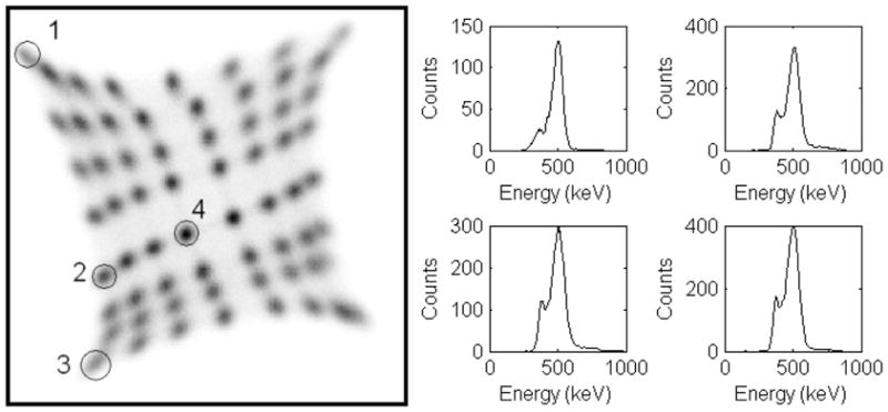
Flood histogram (left) and representative energy spectra (right).
Fig. 5.

Distribution of energy resolution values for each detector element in the system.
B. Sensitivity
With the energy window of 350–650 keV, the sensitivity measured with 22Na at the center of the FOV inside the MRI scanner, but without any MR sequence running, was 0.35%, which is comparable to the GATE [22] simulation result of 0.40%.
C. Scatter fraction
Sinograms were generated from the line source data, aligned and all projection angles were summed. The profiles are shown in Fig. 6. The scatter fractions calculated were 12%, 7% and 5% for the phantom and RF coil, RF coil only and with neither phantom nor RF coil, respectively.
Fig. 6.

Scatter profiles: with phantom and RF coil (solid line), with RF coil only (dashed line) and with neither phantom nor RF coil (dotted line).
The results show that the contribution of the PET insert supporting materials and the MRI scanner to scatter is similar to that of the mouse-sized phantom (~5%). The RF coil contributes less (~2%).
D. Count rate performance
The single event count rates of one detector group are plotted against the activity, and fit to a paralyzable dead time model (Figs. 7a and 7b). The points are the measured data points and the solid line is the fit. The dead time calculated was 390 ns. Only small dead time effects (less than 7% single event loss or less than 14% coincidence event loss) were observed for an activity of 1 mCi (37 MBq) (approximately five times the standard injected dose for a mouse). However, the shaped energy signals are much slower (~1 μs) than the timing signal, so the actual count rate is limited more by pile-up, which causes mispositioning and an energy offset.
Fig. 7.

Count rates and fitting. See text for details.
The count rates before versus after the trigger extension module are plotted in Fig. 7c and fit to a paralyzable dead time model (Fig. 7d). The points are the measured data and the line is the fit. The calculated dead time of the trigger extension module is 7.32 μs.
The prompt rates (solid line with plus sign), random rates (solid line with circle) and true rates (dashed line) for a cylindrical phantom were measured as a function of activity and are plotted in Fig. 8. The random rates were calculated with timing window of 80 ns. These random events include all possible LORs. The NECR (solid line) is also plotted in Fig. 8 (scale on the right). The scatter fractionwas 12% with the phantom and RF coil, k was 0.423, calculated using the phantom diameter of 25.4 mm and the electronic transaxial FOV of 60 mm. The peak NECR of 1.27 kcps was achieved at 290 μCi (10.7 MBq).
Fig. 8.

Count rates: prompt, random, true rates and NECR vs. activity.
E. Reconstructed image spatial resolution
The reconstructed radial and tangential image spatial resolution without any MR sequence running, and with RARE, SE and FLASH sequences, are shown in Table II. The standard deviations were calculated from the 6 repeated experiments. This data demonstrates that the MR sequences had almost no effect on spatial resolution. The average of these three locations’ reconstructed spatial resolution was 1.51 mm.
TABLE II.
Reconstructed Spatial Resolution (mm)
| No Seq. | RARE | SE | FLASH | ||
|---|---|---|---|---|---|
| Center | Radial | 1.34±0.05 | 1.30±0.04 | 1.30±0.07 | 1.31±0.02 |
| Tang. | 1.13±0.06 | 1.13±0.06 | 1.12±0.03 | 1.11±0.05 | |
| 5 mm | Radial | 1.74±0.03 | 1.73±0.02 | 1.72±0.03 | 1.70±0.04 |
| Tang. | 1.58±0.02 | 1.62±0.04 | 1.61±0.04 | 1.60±0.04 | |
| 10 mm | Radial | 1.60±0.03 | 1.57±0.05 | 1.57±0.04 | 1.56±0.03 |
| Tang. | 1.72±0.06 | 1.72±0.06 | 1.74±0.08 | 1.69±0.05 |
F. Phantom study
The ultra-micro hot spot phantom image was reconstructed with FBP and MAP algorithms. The central slices of images are shown in Fig. 9. With FBP reconstruction, the 1.7-mm rods can be clearly resolved and the 1.35-mm rods can be resolved with careful inspection. This data further supports the resolution data in Table II. With MAP reconstruction, the 1.35-mm rods can be clearly resolved and the image has fewer artifacts as anticipated.
Fig. 9.

Ultra-micro hot spot phantom image reconstructed with FBP (left) and MAP (right).
IV. Discussion
The variations in energy resolution are primarily due to the optical fiber bundle [8] and the non-uniformity of gain of the PSAPD. The PSAPDs were divided into two groups, and the same high voltage was applied to each group. Each PSAPD has its own unique gain-voltage characteristics, and thus has a different gain at the same high voltage.
To compare our MR-compatible PET insert with other small animal PET systems, the sensitivity, spatial resolution and NECR are listed in Table III for several microPET scanners [23–26]. The spatial resolution is the average value in the radial and tangential directions. The spatial resolution of this insert is competitive with the first generation microPET prototype [18] and is not affected by the MR system.
TABLE III.
Sensitivity, Spatial Resolution and NECR of Several PET Systems
| Energy Window | Timing Window | Sensitivity at CFOV | Spat. Res. at CFOV | Phantom Size (Diameter, Length) | Peak NECR@ activity | |
|---|---|---|---|---|---|---|
| microPET [23] | 250–650 keV | 12 ns | 0.56% | 1.7 mm | 50.8 mm, 108.5 mm | 4.1 kcps @ 1.76 mCi (65.1 MBq) |
| 350–650 keV | 12 ns | 0.4% | ||||
| microPET R4 [24] | 250–750 keV | 6 ns | 4.37% | 43 mm, 76 mm | 174 kcps @ 2.08 mCi (77 MBq) | |
| 350–750 keV | 6 ns | 1.65 mm | 43 mm, 76 mm | 168 kcps @ 2.46 mCi (91 MBq) | ||
| 350–650 keV | 6 ns | 2.45% | ||||
| microPET Focus 120 [25] | 250–750 keV | 6 ns | 6.7% | 1.34 mm | 25 mm, 70 mm | 809 kcps @ 2.4 mCi (88 MBq) |
| 350–650 keV | 6 ns | 4.4% | 25 mm, 70 mm | ~760 kcps @ ~2.7 mCi (~100 MBq) | ||
| microPET Focus 120 [26] | 250–750 keV | 6 ns | 6.7% | 1.15 mm | 30 mm, 70 mm | 869 kcps @ 4.34 mCi (160.58 MBq) |
| 350–650 keV | 6 ns | 3.8% | 30 mm, 70 mm | 741 kcps @ 4.00 mCi (147.90 MBq) | ||
| this PET insert | 350–650 keV | 80 ns | 0.31% | 1.21 mm | 25.4mm, 70 mm | 1.27 kcps @ 290 μCi (10.7 MBq) |
The sensitivity is however significantly lower than microPET R4 [24] and microPET Focus-F120 [26]. Improved sensitivity can be realized by adding more detector rings axially and/or increasing scintillator length. It should be noted that increasing length may require design to deal with depth-of-interaction (DOI) effect [27]. GATE Monte Carlo simulations suggest that the sensitivity increases to ~1.6% at the CFOV with 4 rings of the same detectors, and to ~6.8% with 4 rings of longer (18 mm long) detectors with the same ring diameter.
The sensitivity measurement and the count rate performance were taken inside the MRI scanner without running any MR sequence. The MR sequences have very small (and not statistically significant) effects on the count rate or sensitivity of the PET system [11]. These effects may be attributed to interference from RF pulses and rapid gradient switching. The ratio of count increase/loss is related to RF power or the gradient strength/switching time and duty cycle of the sequence and therefore depends on the exact sequence. The detailed reasons and solution are still under investigation; however for pulse sequences studied to date, the counting rate and sensitivity are changed by less than 2%, even when running RF or applying gradients at maximum power.
Dead time components of the current DAQ system have been measured, and the NECR was measured with a mouse-sized phantom. Compared with microPET systems, the NECR peaks at lower activity and the peak value is lower. It peaks at 290 μCi (10.7 MBq), which is close to the optimal injected dose for a mouse (typically 100–200 μCi or 3.7–7.4 MBq). For the original microPET scanner, the NECR was around 2 kcps for the same activity of 290 μCi (10.7 MBq) at a concentration of 0.049 MBq/cc in a phantom volume of 220 mL or around 4.5 kcps at a concentration of 0.093 MBq/cc in a phantom volume of 115 mL [23].
The NECR is fairly low because of the wide coincidence window on the current system. It will be dramatically improved in the next generation when upgraded coincidence trigger electronics including crystal-dependent timing shifts will be implemented to account for position-dependent time delays due to the resistive readout of the PSAPDs. This will allow a much narrower coincidence window (~ 12 ns) to be used. The NECR is also expected to vary very slightly with MR pulse sequence, due to the small effects on the counting rate described above. As the effects are smaller than a 2% change in the prompt counting rate, no significant change in the NECR is expected.
One point to note is that on this system, the rates of random coincidence events are estimated from the measured single event rates. However, this slightly overestimates the random rates, as the single event rates also includes single events that result in true coincidence events [28]. Furthermore, the true rates are computed by subtracting the estimated random rates from the measured prompt rates, and therefore an overestimation of the random rates leads to an underestimation of the true rates. The effect of these errors can be estimated by a two-step process in which the random rates are recalculated by using the single rates with the estimated true rates subtracted. At an activity of 290 μCi (10.7 MBq), the overestimation of the random rate was ~5%, the underestimation of true rate was ~9% leading to an estimated underestimation of NECR of ~16%. However, this correction was not applied to the data presented in Fig. 8 as the methodology is yet to be widely accepted, and we therefore prefer to report the more conservative results obtained using conventional NECR calculation.
V. Conclusions and Future Work
These measurements show that the MR-compatible PET insert has good performance inside the MR system when running typical pulse sequences. Overall, the performance of this PET insert is comparable to that of first generation small animal PET systems and therefore is sufficiently good for a wide range of biologically relevant studies, with the advantage of being able to acquire MR data simultaneously. The insert is now being used for a range of mouse studies, while a second generation prototype that significantly improves sensitivity, NECR and axial field of view is under development.
Acknowledgments
This work was supported by the National Institutes of Health under grants R01 EB000993 and R44 NS055377.
The authors thank Russell E. Jacobs and Daniel Procissi from California Institute of Technology for providing help on the MR scanner and for useful discussions and suggestions.
Contributor Information
Yibao Wu, Email: ybwu@ucdavis.edu, Department of Biomedical Engineering, UC Davis, Davis, CA 95616 USA (telephone: 530-752-2809).
Ciprian Catana, Athinoula A. Martinos Center for Biomedical Imaging, Department of Radiology, Massachusetts General Hospital, Charlestown, MA 02129 USA.
Richard Farrell, Radiation Monitoring Devices Inc., Watertown, MA 02472 USA.
Purushottam A. Dokhale, Radiation Monitoring Devices Inc., Watertown, MA 02472 USA
Kanai S. Shah, Radiation Monitoring Devices Inc., Watertown, MA 02472 USA
Jinyi Qi, Department of Biomedical Engineering, UC Davis, Davis, CA 95616 USA.
Simon R. Cherry, Department of Biomedical Engineering, UC Davis, Davis, CA 95616 USA.
References
- 1.Christensen NL, Hammer BE, Heil BG, Fetterly K. Positron Emission Tomography within a Magnetic-Field Using Photomultiplier Tubes and Lightguides. Physics in Medicine and Biology. 1995 Apr;40:691–697. doi: 10.1088/0031-9155/40/4/014. [DOI] [PubMed] [Google Scholar]
- 2.Raylman RR, Majewski S, Lemieux SK, Velan SS, Kross B, Popov V, Smith MF, Weisenberger AG, Zorn C, Marano GD. Simultaneous MRI and PET imaging of a rat brain. Physics in Medicine and Biology. 2006 Dec;51:6371–6379. doi: 10.1088/0031-9155/51/24/006. [DOI] [PubMed] [Google Scholar]
- 3.Shao Y, Cherry SR, Farahani K, Slates R, Silverman RW, Meadors K, Bowery A, Siegel S, Marsden PK, Garlick PB. Development of a PET detector system compatible with MRI/NMR systems. IEEE Transactions on Nuclear Science. 1997 Jun;44:1167–1171. [Google Scholar]
- 4.Mackewn JE, Strul D, Hallett WA, Halsted P, Page RA, Keevil SF, Williams SCR, Cherry SR, Marsden PK. Design and development of an MR-compatible PET scanner for imaging small animals. IEEE Transactions on Nuclear Science. 2005 Oct;52:1376–1380. [Google Scholar]
- 5.Lucas AJ, Hawkes RC, Ansorge RE, Williams GB, Nutt RE, Clark JC, Fryer TA, Carpenter TA. Development of a combined microPET((R))-MR system. Technology in Cancer Research & Treatment. 2006 Aug;5:337–341. doi: 10.1177/153303460600500405. [DOI] [PubMed] [Google Scholar]
- 6.Gilbert KM, Handler WB, Scholl TJ, Odegaard JW, Chronik BA. Design of field-cycled magnetic resonance systems for small animal imaging. Physics in Medicine and Biology. 2006 Jun;51:2825–2841. doi: 10.1088/0031-9155/51/11/010. [DOI] [PubMed] [Google Scholar]
- 7.Pichler BJ, Judenhofer MS, Catana C, Walton JH, Kneilling M, Nutt RE, Siegel SB, Claussen CD, Cherry SR. Performance test of an LSO-APD detector in a 7-T MRI scanner for simultaneous PET/MRI. Journal of Nuclear Medicine. 2006 Apr;47:639–647. [PubMed] [Google Scholar]
- 8.Catana C, Wu YB, Judenhofer MS, Qi JY, Pichler BJ, Cherry SR. Simultaneous acquisition of multislice PET and MR images: Initial results with a MR-compatible PET scanner. Journal of Nuclear Medicine. 2006 Dec;47:1968–1976. [PubMed] [Google Scholar]
- 9.Judenhofer MS, Wehrl HF, Newport DF, Catana C, Siegel SB, Becker M, Thielscher A, Kneilling M, Lichy MP, Eichner M, Klingel K, Reischl G, Widmaier S, Rocken M, Nutt RE, Machulla HJ, Uludag K, Cherry SR, Claussen CD, Pichler BJ. Simultaneous PET-MRI: a new approach for functional and morphological imaging. Nature Medicine. 2008 Apr;14:459–465. doi: 10.1038/nm1700. [DOI] [PubMed] [Google Scholar]
- 10.Woody C, Schlyer D, Vaska P, Tomasi D, Solis-Najera S, Rooney W, Pratte JF, Junnarkar S, Stoll S, Master Z, Purschke M, Park SJ, Southekal S, Kriplani A, Krishnamoorthy S, Maramraju S, O’Connor P, Radeka V. Preliminary studies of a simultaneous PET/MRI scanner based on the RatCAP small animal tomograph. Nuclear Instruments & Methods in Physics Research Section a-Accelerators Spectrometers Detectors and Associated Equipment. 2007;571:102–105. [Google Scholar]
- 11.Catana C, Procissi D, Wu Y, Judenhofer MS, Qi JY, Pichler BJ, Jacobs RE, Cherry SR. Simultaneous in vivo positron emission tomography and magnetic resonance imaging. Proceedings of the National Academy of Sciences of the United States of America. 2008 Mar;105:3705–3710. doi: 10.1073/pnas.0711622105. [DOI] [PMC free article] [PubMed] [Google Scholar]
- 12.Shah KS, Grazioso R, Farrell R, Glodo J, McClish M, Entine G, Dokhale P, Cherry SR. Position sensitive APDs for small animal PET imaging. IEEE Transactions on Nuclear Science. 2004 Feb;51:91–95. [Google Scholar]
- 13.Wu Y, Catana C, Cherry SR. A multiplexer design for position-sensitive avalanche photodiode detectors in a PET scanner. IEEE Transactions on Nuclear Science. 2008 Feb;55:463–468. [Google Scholar]
- 14.Judenhofer MS, Pichler BJ, Cherry SR. Evaluation of high performance data acquisition boards for simultaneous sampling of fast signals from PET detectors. Physics in Medicine and Biology. 2005 Jan 7;50:29–44. doi: 10.1088/0031-9155/50/1/003. [DOI] [PubMed] [Google Scholar]
- 15.Qi JY, Leahy RM. Resolution and noise properties of MAP reconstruction for fully 3-D PET. IEEE Transactions on Medical Imaging. 2000 May;19:493–506. doi: 10.1109/42.870259. [DOI] [PubMed] [Google Scholar]
- 16.Yang YF, Cherry SR. Observations regarding scatter fraction and NEC measurements for small animal PET. IEEE Transactions on Nuclear Science. 2006 Feb;53:127–132. [Google Scholar]
- 17.Knoll GF. Radiation Detection and Measurement. 3. John Wiley & Sons Inc; 2000. [Google Scholar]
- 18.Strother SC, Casey ME, Hoffman EJ. Measuring PET scanner sensitivity - relating countrates to image signal-to-noise ratios using noise equivalent counts. IEEE Transactions on Nuclear Science. 1990 Apr;37:783–788. [Google Scholar]
- 19.Shah KS, Farrell R, Grazioso R, Harmon ES, Karplus E. Position-sensitive avalanche photodiodes for gamma-ray imaging. Nuclear Science, IEEE Transactions on. 2002;49:1687–1692. [Google Scholar]
- 20.Zhang J, Olcott PD, Levin CS. A new positioning algorithm for position-sensitive avalanche photodiodes. IEEE Transactions on Nuclear Science. 2007 Jun;54:433–437. doi: 10.1109/TNS.2007.894129. [DOI] [PMC free article] [PubMed] [Google Scholar]
- 21.Chaudhari AJ, Joshi AA, Bowen SL, Leahy RM, Cherry SR, Badawi RD. Crystal identification in positron emission tomography using nonrigid registration to a Fourier-based template. Physics in Medicine and Biology. 2008 Sep;53:5011–5027. doi: 10.1088/0031-9155/53/18/011. [DOI] [PMC free article] [PubMed] [Google Scholar]
- 22.Jan S, Santin G, Strul D, Staelens S, Assie K, Autret D, Avner S, Barbier R, Bardies M, Bloomfield PM, Brasse D, Breton V, Bruyndonckx P, Buvat I, Chatziioannou AF, Choi Y, Chung YH, Comtat C, Donnarieix D, Ferrer L, Glick SJ, Groiselle CJ, Guez D, Honore PF, Kerhoas-Cavata S, Kirov AS, Kohli V, Koole M, Krieguer M, van der Laan DJ, Lamare F, Largeron G, Lartizien C, Lazaro D, Maas MC, Maigne L, Mayet F, Melot F, Merheb C, Pennacchio E, Perez J, Pietrzyk U, Rannou FR, Rey M, Schaart DR, Schmidtlein CR, Simon L, Song TY, Vieira JM, Visvikis D, de Walle RV, Wieers E, Morel C. GATE: a simulation toolkit for PET and SPECT. Physics in Medicine and Biology. 2004 Oct;49:4543–4561. doi: 10.1088/0031-9155/49/19/007. [DOI] [PMC free article] [PubMed] [Google Scholar]
- 23.Chatziioannou AF, Cherry SR, Shao YP, Silverman RW, Meadors K, Farquhar TH, Pedarsani M, Phelps ME. Performance evaluation of microPET: A high-resolution lutetium oxyorthosilicate PET scanner for animal imaging. Journal of Nuclear Medicine. 1999 Jul;40:1164–1175. [PMC free article] [PubMed] [Google Scholar]
- 24.Knoess C, Siegel S, Smith A, Newport D, Richerzhagen R, Winkeler A, Jacobs A, Goble RN, Graf R, Wienhard K, Heiss WD. Performance evaluation of the microPET R4 PET scanner for rodents. European Journal of Nuclear Medicine and Molecular Imaging. 2003 May;30:737–747. doi: 10.1007/s00259-002-1052-6. [DOI] [PubMed] [Google Scholar]
- 25.Laforest R, Longford D, Siegel S, Newport DF, Yap J. Performance evaluation of the microPET (R) - FOCUS-F120. IEEE Transactions on Nuclear Science. 2007 Feb;54:42–49. [Google Scholar]
- 26.Kim JS, Lee JS, Im KC, Kim SJ, Kim SY, Lee DS, Moon DH. Performance measurement of the microPET focus 120 scanner. Journal of Nuclear Medicine. 2007 Sep;48:1527–1535. doi: 10.2967/jnumed.107.040550. [DOI] [PubMed] [Google Scholar]
- 27.Moses WW, Derenzo SE, Melcher CL, Manente RA. Room-Temperature Lso Pin Photodiode Pet Detector Module That Measures Depth of Interaction. IEEE Transactions on Nuclear Science. 1995 Aug;42:1085–1089. [Google Scholar]
- 28.Oliver J, Rafecas M. Estimation of random coincidences: Revisiting the singles rate method for high resolution PET. Journal of Nuclear Medicine Meeting Abstracts. 2008 May 1;49:391P. [Google Scholar]