Abstract
Introduction
When navigating a needle from skin to epidural space, a skilled clinician maintains a mental model of the anatomy and uses the various forms of haptic and visual feedback to track the location of the needle tip. Simulating the procedure requires an actuator that can produce the feel of tissue layers even as the needle direction changes from the ideal path.
Methods
A new actuator and algorithm architecture simulate forces associated with passing a needle through varying tissue layers. The actuator uses a set of cables to suspend a needle holder. The cables are wound onto spools controlled by brushless motors. An electromagnetic tracker is used to monitor the position of the needle tip.
Results
Novice and expert clinicians simulated epidural insertion with the simulator. Preliminary depth-time curves show that the user responds to changes in tissue properties as the needle is advanced. Some discrepancy in clinician response indicates that the feel of the simulator is sensitive to technique, thus perfect tissue property simulation has not been achieved.
Conclusions
The new simulator is able to approximately reproduce properties of complex multilayer tissue structures, including fine-scale texture. Methods for improving fidelity of the simulation are identified.
INTRODUCTION
This simulator was developed for training clinicians to insert an epidural anesthesia needle. Many aspects of epidural simulation are also essential features for other procedures that require haptic feedback. Thus, the design is more generally a means of recreating the feel of passing a needle through tissue layers.
Epidural analgesia 1–3 is commonly used for childbirth, post-operative pain relief, and other situations requiring lower-body anesthesia. It involves placement of a catheter in the epidural space. This space, about 3 mm deep, surrounds the dural sheath that protects the spinal cord and contains the cerebrospinal fluid. The catheter is guided into the space through a needle. Accidentally puncturing the dura with the needle results in a leak of cerebrospinal fluid and associated headaches that can persist for days or weeks4. A trainee must learn to stop advancing the needle once the tip enters the epidural space.
For a midline approach to the epidural space, the clinician advances the needle between the spinous processes at the appropriate vertebral level. The needle must pass through five distinct tissue layers: Skin, subcutaneous fat, supraspinous ligament, interspinous ligament, and ligamentum flavum. The epidural space is then encountered and the clinician must stop the advancement of the needle before it penetrates the dural sheath. (Figure 1). Most clinician use a “loss-of-resistance” technique to identify the epidural space. In this technique, a syringe with a low-resistance plunger is attached to the end of the epidural needle. The clinician attempts to inject air or saline through the needle as it is advanced. The firm ligamentous structures resist this injection. When the tip of the needle enters the epidural space, the air or saline can then be easily injected (the “loss of resistance”), and the clinician stops advancement of the needle.
Figure 1.
Anatomy of epidural simulation.
Navigating from skin to epidural space requires feedback such as the feel of the tissue layers (e.g., toughness, texture, elasticity), depth of the needle based on the remaining length of exposed needle, and the ability of the tissue to support the needle and syringe. A skilled clinician maintains a mental model of the anatomy and uses the various forms of feedback to track the location of the needle tip. Typical descriptions of the tissue layers (see Figure 1) are that the superspinous ligament is “crunchy”, the interspinous ligament is smooth, and the ligamentum flavum is tough “like tire rubber”. Simulating the procedure requires an actuator that can produce the feel of tissue layers even as the needle direction changes from the ideal path.
The challenge of epidural simulation has attracted the attention of many engineers5–8 due to the demands of the task, as it creates an opportunity to demonstrate a range of automation, control, sensing, and modeling technologies. We describe the development and initial clinical validation of a novel epidural actuator that produces forces on the needle in multiple directions, as if one were probing an elastic sheet with the needle, using only simple control of tension in wires supporting the needle. A series of the simulated sheets are combined in sequence to produce the feel of inserting through many layers.
METHODS
This simulator includes needle position tracking, gross and fine tissue property simulation, syringe loss-of-resistance, and graphical procedure monitoring. In this paper, we summarize the mechanical and electrical designs and present the tissue simulation algorithm.
Actuator Concept
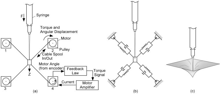
The actuator (Figure 2) simulates a haptic experience similar to penetrating tissue with a needle, allowing displacements off the primary needle axis. The needle is attached to a receptacle supported by four wires. The simulator sets the apparent properties of the tissue with the elastic and damping properties of the individual cables.
Figure 2.
Nomenclature and equivalent models for tissue layer simulator. This example shows all four monitors and the needle in one plane for simplicity.
This simplified example has only a single-axis of motion, and all cables are in a single plane. The components in Fig. 2(a) simulate the system in 2(b), which mimic the forces associated with the physical arrangement in 2(c). Each wire is wound onto a spool on the shaft of a brushless motor. Encoders measure the angular position of the shaft, and hence the extension or contraction of the cables. A motor drive amplifier controls torque by controlling the motor phase currents in response to a torque command voltage from the control computer.
The (simplified) feedback law for the motor control loop is to apply a motor torque that is the sum of three quantities. The first is a term proportional to the rotation of the motor since entering the tissue layer. The second is a term proportional to the rate at which the cable is spooling in or out. The third term is a constant torque used to maintain minimal tension in the cables to prevent slacking and to increase the side-to-side stiffness as the needle moves into the deeper layers. Moving the needle along the direction of its axis causes upper cables to spool out and lower cables to spool in. For small displacements of the needle along its axis, the force applied consists of a component proportional to the displacement since entering the tissue layer (creating a spring-like feel) plus one proportional to the rate of needle movement (producing the drag felt when advancing the needle). Thus a damped elastic reaction is applied to the needle as it moves into the virtual tissue. A similar analysis can be used to show how this type of feedback to the motor produces elastic and drag forces if the needle is rotated about an axis perpendicular to the plane of the cables, or if it is translated within that plane. The force along the needle does not include a term due to the mean tension because it is balanced among the cables in the nominal condition shown. For rotation perpendicular to the plane of the cables, the mean tension controls the restoring torque on the needle. Thus, the mean tension can be used to adjust the tendency of the needle to flop, but it does not affect the force associated with advancing the needle.
The above analysis is true for small motions of the needle. In the implementation of the simulator, movement may be large. However, the deflections within any given tissue layer are small, so the force is approximately linear within a layer.
Simulator System Design
The epidural simulator consists of four major elements: a laptop computer hosting the user interface and the upper-level simulation control, an electronics box, an instrumented syringe/needle, and mechanical simulator.
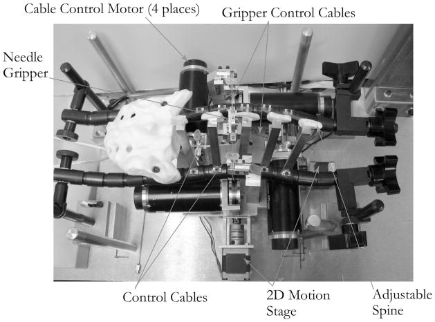
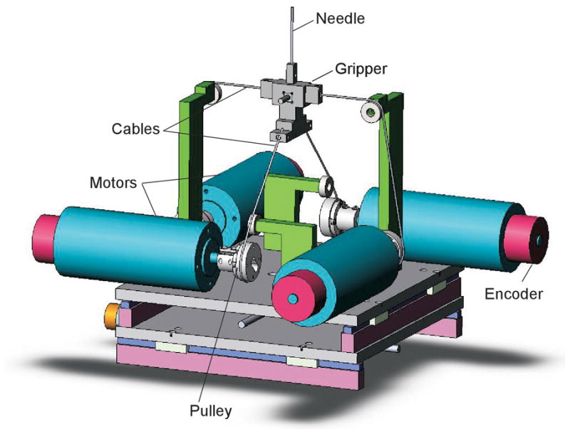
Figure 3 shows the mechanical components of the epidural simulator, and Figure 4 shows the kinematic arrangement of the motors and cables. The four brushless motors (Maxon EC Max 333347) were fitted with optical shaft position encoders. The cables were 0.5 mm stainless steel wire rope, chosen for its tensile stiffness, because it is important to concentrate all of the elasticity in the motor feedback loop. The needle gripper consisted of a plastic support frame, with associated cable attachment points, and a needle clamping mechanism.
Figure 3.
Internal simulator components, viewed from the top.
Figure 4.
Kinematic arrangement of the cables and motors. The upper and lower cable sets are in perpendicular planes that intersect along the axis of the needle.
A 16 Ga, 60 mm long needle was attached to a loss-of-resistance syringe (Pulsator LOR Syringe, 7 mL. Smith Medical, Keene, NH, USA). The syringe was blocked at its exit to prevent fluid flow to the needle, and a 1.5 mm diameter × 80 cm long flexible tube connected a port on the side of the syringe to a solenoid valve. The loss-of-resistance technique could thus be simulated with the controller opening the valve to syringe flow when the needle tip enters the virtual epidural space.
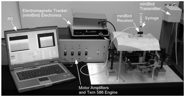
The actuator assembly is contained within a physical model of the lumbar spine. An adjustable spine was constructed by attaching plastic spinous processes to a pair of Flexbar® adjustable linkages. This allowed for adjustment of both the flexion and lateral curvature of the spine. A skin/fat layer and lower torso can be positioned over the apparatus shown in Figure 3 to produce the full simulator assembly shown in Figure 5.
Figure 5.
Complete epidural simulator system.
Electronic Control
Figure 6 shows the electronic control system. There are two separate processing centers. The Tern 586 E-engine performs real-time control functions. A laptop personal computer (PC) receives needle position information from the tracker, determines the current needle layer, and transmits the current layer parameters to the 586 E-engine via RS-232 serial link.
Figure 6.
Electronic control system for simulator.
Needle tip position is determined by a 6-degree-of-freedom electromagnetic tracking system (miniBIRD, Ascension Technologies, Burlington, VT). The receiver for the tracker is a 5 mm × 5 mm × 10 mm device with an attached cable. The receiver is mounted in the plastic needle gripper frame. The plastic frame material was chosen to minimize interference with the electromagnetic field.
A set of brushless motor controllers (Aerotek BAS-10 Sinedrive) control the motor current in response to voltage commands from the 586 Engine-P. This was done using two separate analog output channels. The feedback channel that produced elasticity and drag included only signal frequencies below 3 Hz, as an electronic filter removed higher frequencies to prevent control-induced oscillation. The filters also prevent the needle buzzing that results from controller noise. A separate analog output channel produced high-frequency signals to simulate the texture of various tissues as described below.
Motor Control
The motor torque commands are produced as the sum of three terms – the force-balance term, tissue property term, and texture term. The first two are summed in the software, and the third is added through an analog summing circuit.
Force Balance
The force balance term counters the weight of the needle and syringe, so there is a net zero force on the syringe at any depth. This prevents the simulator from moving in the event that the user releases the syringe. While it is possible to calculate a theoretical balance force based upon the controllability matrix describe earlier, this theoretical solution contains secant functions which are nearly singular at the boundaries of the z motion. We used an exponential function to approximate the secant function, and this was successful in countering the gravity loads.
Algorithm for tissue simulation 9–11
Simulating a complex group of tissues was accomplished by defining discrete tissue layers, specifying their characteristics, and changing the tissue properties when the needle changes layers. For each tissue layer j, we specify the following parameters
Dimensions – Length, width, and depth of the tissue layer
Elasticity – (K p,j) Force/Deflection parameter
Drag – (K d,i) Force/velocity parameter, represents friction of needle sliding through tissue
Mean Tension – (τ0,j) Mean cable tension, also represents mean motor torque
Transition Time Constant – (αj) Defines abruptness of transition
Texture Properties – (Tm,j, Ts,j) Relative Magnitude and spacing of fine structure
At any time, the current tissue layer is determined from needle tip location as measured by the electromagnetic tracker. Whenever the needle tip moves from one layer to another, the laptop PC transmits the new parameters to the 586 E-engine.
All of the motor control calculations run on the Tern loop rate of 500 Hz. They are performed for each motor. Thus, the spring and damping terms are based on displacement and angular velocity of the motors, as measured by the encoders – not the position of the needle itself.
The spring term produces a force proportional to the displacement from the start of each layer. For damping, motor velocity was estimated by taking an N-sample backward difference and applying a low-pass filter (see equations below). Some modifications from the simple spring/damper equation were developed through test experience and sequential algorithm changes.
As a needle passes through a layer of real tissue, small displacements of the needle that do not sever tissue result in the elastic feeling as the tissue pushes back on the needle. As the needle advances, it cuts the tissue slowly, relaxing the elastic forces. Thus, we apply a high-pass filter (cutoff frequency = 0.4 Hz) to the elastic term so that the elastic component of force diminishes when the needle is held in a given position for a few seconds. If the needle is pushed in quickly a small amount and released, it will spring back, but if it is advanced slowly or if it is pushed in a few millimeters and held in place, it will not spring back.
Another modification was needed for the spools to wind up loose cable. When the needle is pushed in, tension in the lower cables is reduced, and the cables are slack. With high damping, the motors do not take up the cable quickly, so the damping term is capped at a saturation level on wind-up. Also, since the elastic term is applied for displacements from a nominal position for each layer, winding cable would result in an elastic term that tends to unwind to the point where the layer started. Thus, we do not include the elastic term during wind-up.
In the implementation of the simulator, the tissue component of the torque contains the spring, damping, and mean tension pieces. Some additional features are necessary to produce a realistic simulation. First, the elastic term is omitted when the needle is being pulled out. The direction of motion is determined from the difference in consecutive motor angle measurements. Second, there is a maximum drag force on the needle. Finally, the elastic term is applied only after changes in needle position. If the needle is held in place the force relaxes, simulating the effects of tissue relaxation.
Texture Simulation
The feeling of “crunchiness” in a ligament results from breaking through individual fibers. Two parameters are used to describe texture for the simulation. These are the magnitude of the texture (i.e., how strong the fibers are) and the texture spacing (how far apart the structures are). To create the texture feeling, the controller monitors the average encoder position of the upper motors. Each time the average encoder count changes by the amount specified by the texture spacing, a pulse (whose voltage is proportional to the absolute texture magnitude) is generated from the texture output channel. The pulse duration is one control cycle. This is added to the low-frequency torque command, so that a pulse of tension is felt in the needle. The pulse is only added when the encoder motion indicates the upper cables are spooling out, indicating the needle is moving deeper. There is thus no texture felt when the needle is pulled back.
Layer Transition
The location of the needle tip is determined from the tracker’s measurements. When the tip moves from one layer to another a transition process begins. When a forward transition occurs, the abruptness parameter for transition into the new layer specifies a transition time between 2 ms and 1 sec. During this time no other transition can begin. The parameters (elasticity, drag, mean tension) are changed linearly from the old values to the new values over the transition time.
Some layers have an abrupt transition – often described as a “pop”, produced by setting the transition time very low. Others (for example, moving from interspinous ligament to ligamentum flavum) have a slow transition, with no “pop” from rupturing a tough membrane, and thus have a longer transition time.
Simulator Evaluation and Validation
Two collaborating anesthesiologists (PH & SP) evaluated the simulator to provide feedback on the “feel” of the virtual tissue layers and the transitions between layers. A lack of consistency between the recommendations of the consultants suggested that the simulation experience depends on technique (e.g., speed of needle advancement). This indicates we did not achieve a true tissue property simulation, but one that approximates tissue properties over a limited range of procedure parameters.
We then asked a series of clinicians, ranging from novices to expert clinical instructors in obstetric anesthesia to use the simulator. The intent was to determine if performance on the simulator, as quantified by time/position curves, was consistent with clinician experience levels. This trial was conducted at the Beth Israel-Deaconess Medical Center in Boston, MA, under a protocol approved by the Committee on Clinical Investigation. We summarize initial observations below and show time/position data, though a full report of the trial is beyond the scope of this paper.
RESULTS
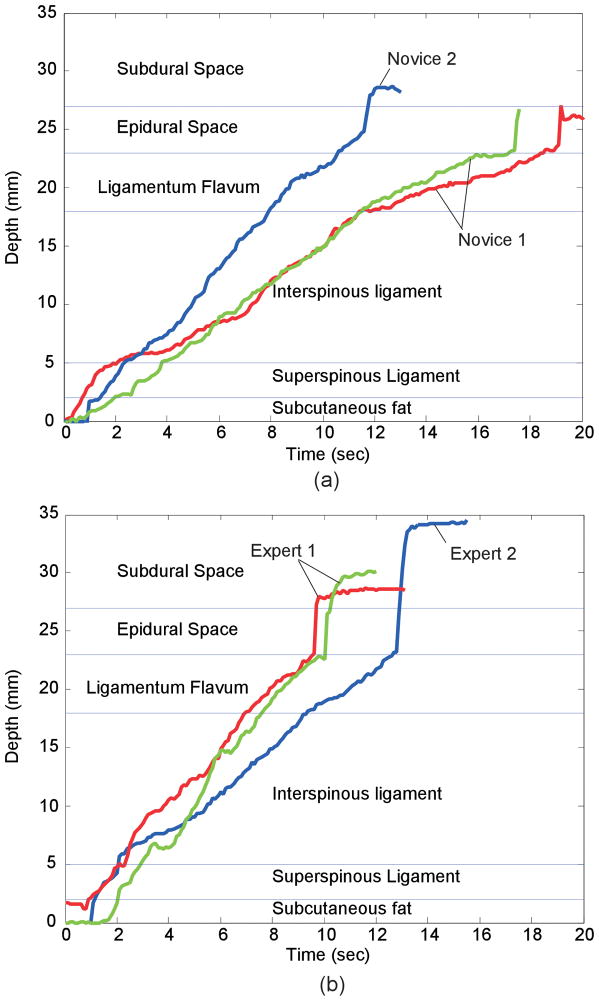
Each simulated procedure began with the needle in subcutaneous fat, and ended when the user identified loss-of-resistance. Figure 7 shows the results of several representative simulations, depicting the depth of the needle as a function of time. In each graph, two curves are repetitions of a single user and the third is from a different user. In the repeated trials by the same user, the rates of motion (indicated by the slopes of the lines) are similar, though different users appear to have different rates of motion.
Figure 7.
Time-depth plots for (a) novices (<35 Procedures) and (b)experts inserting the needle in simulator. Each plot shows two trials from one user and one from a different user.
In all six plots, there is a change in slope (velocity) or brief pause as the needle moves into the interspinous ligament, indicating that the user felt the increase in resistance to moving the needle. Likewise, the plots show a decrease in slope associated with entering the ligamentum flavum. All traces show the sudden acceleration associated with exiting the flavum and entering the epidural space. In several of the cases shown here, the user pauses forward motion briefly when the needle exits the supraspinous ligament and again just before they enter the epidural space. The needle punctures the dura in four of the six cases, and the event is more pronounced in trials by experts than by the novices.
DISCUSSION
Initial testing of the simulator demonstrated that both expert and novice anesthesiologists were able to identify changes in the resistance at each virtual tissue plane, as evidenced by the change in the slope of the speed of advancement through each plane. Most notably, the slope decreases when entering the ligamentum flavum – the toughest of the layers – and increases rapidly when the needle tip enters the epidural space and undergoes the sudden drop in resistance. The pause as the clinicians entered both the supraspinous ligament and the ligamentum flavum suggests that they were able to identify the transitions from one tissue plane to the next. The ability to simulate the transition between tissue layers is important as it would help teach clinicians to anticipate the loss of resistance as they penetrate the ligamentum flavum.
One comment from several clinicians is that the resistance to flow remained too high after loss-of-resistance, diminishing the “pop” felt when the epidural space is entered. The pop is the result of both the entire syringe moving forward and motion of the plunger within the syringe, both occurring when the needle tip is beyond the ligamentum flavum. The engineers tuned the simulator based on comments from the clinicians, but no single investigator on this project had both the experience with placing epidurals and the expertise to tune the simulator. Since the experts all advanced the needle tip well past the epidural space, it appears that the effect was created with too much whole-syringe motion and too little plunger motion.
With a lower resistance in the flow path, a more pronounced pop might be felt in the syringe without allowing the needle to move forward rapidly. A larger-orifice valve and larger tube were tried as a remedy, to increase the flow of water out of the syringe. The larger valve produced an audible click on opening – a tip for the user that they are in the epidural space. Improving this feature is one of the engineering challenges for the next generation of simulators.
Other epidural simulators have been described, ranging from fruits12 and vegetables,13 to simple mechanical devices,14, 15 to virtual reality models on a computer screen.16 The simulator described in this paper is the first electromechanical simulator to incorporate a physical model of the spine so the trainee can gain experience at palpating the bony landmarks prior to insertion of the epidural needle. Further, because the software can be easily and rapidly reprogrammed, the device could be modified to simulate many clinical scenarios, from a routine epidural for novices, to scoliosis or morbid obesity for more advanced training. The visual time/depth curves might allow assessment of a trainee’s improvement in techniques over time. Finally, the device could be modified to teach other procedures in which the clinician must learn the feel of advancing a needle through multiple tissue planes, including central line placement, lumbar punctures, or thoracentesis.
The current model does have limitations. First, the consultant physicians provided differing, and sometimes conflicting, recommendations about the haptic “feel” of the tissues. This suggests that variations in individual technique may contribute to the tactile experience of placing an epidural. This may limit the universal applicability of the device. In addition, while the trainee can learn to palpate the lumbar spine, they cannot choose where to place the needle. This choice can be critical to the success of an attempted epidural placement.
Ultimately we hope to validate this epidural simulator and to demonstrate that trainees exposed to it are more rapidly able to gain expertise in the actual placement of an epidural catheter.
CONCLUSION
The cable system actuator allows creation of multi-dimensional tissue feel from a set of simple motor control algorithms. The control algorithms allow simulation of epidural anesthesia and other procedures that involve passing a needle through multiple tissue layers where coarse and fine tissue properties are important. Time/depth curves for a novice and an experienced clinician were shown. Changes in the rate of needle advancement show users experiencing simulated tissue property changes at layer transitions. Some observations, such as discrepancies in comments from clinicians about the feel of the device, indicate the simulator does not yet reproduce some tissue features properly. Improving the loss-of-resistance mechanism, and refining and tuning the tissue models are expected to improve these attributes of the simulation.
Acknowledgments
This work was sponsored under Phase II SBIR grant 2 R44 EB000365-02A2 from the National Institutes for Health (NIBIB and NCMH).
References
- 1.April EW. The National Medical Series for Independent Study: Anatomy. Harwal Publishing, Media; PA: 1984. [Google Scholar]
- 2.Moir DD, Thorburn J. Obstetric Anaesthesia and Analgesia. Bailliere Tindall; London: 1986. p. 238. [Google Scholar]
- 3.Kopacz DJ, Neal JM, Pollock JE. The regional anesthesia “learning curve”. What is the minimum number of epidural and spinal blocks to reach consistency? Reg Anesth. 1996 May–Jun;21(3):182–90. [PubMed] [Google Scholar]
- 4.Norris MC, Grieco WM, Borkowski M, Leighton BL, Arkoosh VA, Huffnagle HJ, Huffnagle S. Complications of Labor Analgesia: Epidural versus combined spinal techniques. Anesth Analg. 1994;79(3):529–37. doi: 10.1213/00000539-199409000-00022. [DOI] [PubMed] [Google Scholar]
- 5.Daykin AP, Bacon RJ. An Epidural Injection Simulator. Anaesthesia. 1990;45:235–236. doi: 10.1111/j.1365-2044.1990.tb14694.x. [DOI] [PubMed] [Google Scholar]
- 6.Gillespie B, Rosenberg LB. Design of High-Fidelity Haptic Display for One-Dimensional Force Reflection Applications. Proceedings of SPIE. 1995;2351:44–54. [Google Scholar]
- 7.Reznek MA, Rawn CL, Krummel TM. Evaluation of the educational effectiveness of a virtual reality intravenous insertion simulator. Academic Emergency Medicine. 2002 Nov;9(11):1319–25. doi: 10.1111/j.1553-2712.2002.tb01594.x. [DOI] [PubMed] [Google Scholar]
- 8.Stredney D, Sessanna D, McDonald JS, Hiemenez L, Rosenberg LB. In: A Virtual Simulation Environment for Learning Epidural Anesthesia, Health Care in the Information Age, Chapter 20. Sieburg S, Weghorst SJ, editors. IOS Press and Ohmsha; 1996. pp. 164–175. [PubMed] [Google Scholar]
- 9.Brett PN, Parker TJ, Harrison AJ, Thomas TA, Carr A. Simulation of Resistance Forces Acting on Surgical Needles. Proc Inst Mech Engrs. 1997;211(Part H):335–347. doi: 10.1243/0954411971534467. [DOI] [PubMed] [Google Scholar]
- 10.Brett PN, Harrison AJ, Thomas TA. Schemes for the Identification of Tissue Types and Boundaries at the Tool Point for Surgical Needles, IEEE Transactions on Information Tech. Biomedicine. 2000 March;4(1):30–36. doi: 10.1109/4233.826856. [DOI] [PubMed] [Google Scholar]
- 11.Langton JA, Meiklejohn BH. Pressure Generated During Insertion of Lumbar Epidurals. Anaesthesia. 1990;45:1055–1056. doi: 10.1111/j.1365-2044.1990.tb14888.x. [DOI] [PubMed] [Google Scholar]
- 12.Leighton B. A Greengrocer’s model of the epidural space. Anesthesiology. 1989;70:368–9. [PubMed] [Google Scholar]
- 13.Tuckey J. The epidural potato! Anaesthesia. 1998;53:1232. doi: 10.1046/j.1365-2044.1998.0716h.x. [DOI] [PubMed] [Google Scholar]
- 14.Daykin AP, Bacon RJ. An epidural injection simulator. Anaesthesia. 1990;45:235–6. doi: 10.1111/j.1365-2044.1990.tb14694.x. [DOI] [PubMed] [Google Scholar]
- 15.Paw HG. A trainer for identification of the epidural space. Anaesthesia. 1995;50:914. doi: 10.1111/j.1365-2044.1995.tb05871.x. [DOI] [PubMed] [Google Scholar]
- 16.Glassenberg R, Glassenberg S. Development of a Tactile Feedback Simulator for Placement of an Epidural or Spinal Needle. Anesthesiology. 2004;101:A1358. [Google Scholar]


