Abstract
The current wear-testing standard (ISO18192-1) for total disc replacement (TDR) requires only four degrees of freedom (DOF) inputs: axial load, flexion–extension, lateral bending and axial rotation. The study aim was to assess the effect of an additional DOF, anterior–posterior (AP) shear on the wear of the ProDisc-L TDR. A 5DOF simulator was used to test ProDisc-L implants under 4DOF and 5DOF conditions. The 4DOF conditions were defined by ISO18192-1 whilst the 5DOF used ISO18192-1 conditions with the addition of an AP load of +175 and −140 N (anterior and posterior, respectively), extrapolated from in vivo data. The implants were mounted such that the polyethylene insert could be removed for gravimetric measurements. Tests were run using bovine serum (15 g/l protein concentration) as a lubricant for five million cycles (MC), with measurements repeated every 1 MC. The mean wear rate in the 4DOF test was 12.7 ± 2.1 mg/MC compared to 11.6 ± 1.2 mg/MC in the 5DOF test. There were marked differences in the wear scars between 4DOF and 5DOF simulations. With 4DOF, wear scars were centralised on the dome of the insert, whilst 5DOF scars were larger, breaching the anterior rim of the dome causing deformation at the edge. The 4DOF wear test showed similar gravimetric wear rates to previously published ISO-tested TDRs. The addition of AP load was found to have no significant effect on the overall wear rate. However, there were pronounced differences in the respective wear scars, which highlights the need for more research in order to understand the factors that influence wear of TDR.
Keywords: Total disc replacement, TDR, Wear, ProDisc-L
Introduction
The most widely implanted lumbar total disc replacements (TDR) to date have been those based upon a metal-polyethylene design. In the short term, these devices have been as successful in terms of pain relief and patient satisfaction as spinal fusion [1–4]. Revision rates of lumbar TDR, at 6–11.2% [5, 6], are also comparable to fusion, at 5.8–22% [6, 7] within 2 years. However, there are concerns that these articulating designs may be subject to long-term failure due to wear, which has been widely documented in total hip and knee arthroplasty [8]. There is a growing body of evidence that polyethylene wear debris has osteolytic potential in the spine, and specific cases of TDR-related osteolysis have now begun to emerge [9–11]. As TDR implantation times reach 10–15 years, the time at which osteolysis is typically documented in hip and knee replacements, the number of such cases is likely to increase.
Physical wear simulations of metal-on-polyethylene TDR have had input conditions restricted to those specified by the ISO standard [12] or the ASTM standard guide [13]. The results of these tests have been similar to those observed in other metal-polyethylene articulating devices, with wear rates being within the 2–20 mm3/MC range [14–17]. Although comparisons to other implants are useful, further research needs to be undertaken in order to understand the wear processes within TDR, the tribological conditions that will be specific to TDR and the effect of wear debris upon local spinal tissues, particularly with reference to macrophage activation and osteolysis.
Current TDR wear simulators test a maximum of 4DOF; axial loading, flexion/extension rotation, lateral bending rotation and axial rotation, as defined by White and Panjabi [18]. Two other DOF exist in principle: anterior–posterior (AP) and lateral shears, neither of which has been actively applied to TDR wear simulations to date. The magnitude of these shear loads has been measured to be in the range of 100–200 N during walking [19], but as high as 400 N in most lumbar joints, reaching 1,000 N in L5–S1 [20]. There is debate about the effect of AP shear in particular, and the effect that this loading component may have on the TDR itself and on the facet joints [21].
The aim of this study was to compare the wear of metal-on-polyethylene TDR in ISO standard 4DOF wear tests versus otherwise similar tests with 5DOF input, using a new 5DOF simulator developed by University of Leeds and Simulation Solutions (Manchester, UK) [22]. The ISO standard test was run using a fixed-bearing ProDisc lumbar TDR and the results were compared to previously published data. The same simulator was then used to run the 5DOF test with the same device, incorporating an AP shear load to investigate the affect of this additional DOF testing on the wear rate and wear mechanisms.
Methods
The ProDisc-L consists of a two cobalt–chromium molybdenum endplates, with a polyethylene core (GUR1020, inert gamma sterilised at 2.5–4 MRads) that locks onto the inferior endplate. The bearing is therefore classified as a fixed-bearing, constrained TDR, as it allows little to no translation, only rotations.
Seven ProDisc-L implants were fixed into test cells using PMMA bone cement, such that the centre of rotation of the implant would be coincident with that of the simulator and the polyethylene insert could be removed for measurement. The polyethylene inserts were soaked in distilled water for 2 weeks in order to stabilise fluid absorption, and then stored in a sealed, dust free container, in a temperature (22°C) and humidity (45%) controlled environment for 48 h to stabilise their mass. Their pre-test masses were determined gravimetrically on a digital balance with a resolution of 0.01 mg (Mettler-Toledo Inc, Columbus, Ohio).
After measurement, the polyethylene inlays were inserted into the inferior endplate and the test cells assembled by locating the polyethylene dome onto the superior endplate. The test cells were enclosed in a silicon bag, which were secured to the test cells with jubilee clips (hose clamps). The test cells were then located in the required test station and secured with two screws on both the inferior and superior test cell. Once all cells had been assembled and inserted into the test station, pipes were connected to the fluid port for each cell and the silicon bag filled with a lubricating solution of bovine serum (15 g/l protein concentration) with 0.03% (wt/vol) sodium azide to minimise microbial contamination. ISO18192-1 determines a protein concentration of 30 g/l, but concentrations of 5–25 g/l have been shown to produce clinically relevant wear rates in TJR [23].
Each test was run for five million cycles (5 MC), shorter than that 10 MC specified by the ISO standard. Historically, wear tests of joint replacements have shown that wear rates reach steady state after the first few million cycles, as has been suggested to be the case with TDR [14]. The lubricating fluid was removed every 1/3 MC and stored at −20°C for future wear debris analysis. The test cells were then washed through with soapy water, soaked in disinfectant solution and rinsed with tap water and then de-ionised water before refilling with fresh lubricant. At every 1 MC time point, the test cells were thoroughly cleaned, including an overnight soak in disinfectant solution. The polyethylene inserts were removed from the inferior endplate, washed, ultrasonically cleaned and soaked in iso-propanol before being stored for 48 h prior to weighing. The net mass loss was then calculated according to ISO14242-2, adjusting for fluid absorption using the mass increase of the control specimen. The mass measurements were repeated six times, and the mean mass loss calculated.
Wear scars were traced with a marker pen and the disc was digitally photographed with a scale. These images were then analysed in ImageProPlus (MediaCybernetics Inc., Bethesda, MD) to measure the wear scar area by the same observer each time; intra-observer error was up to 16% when both tracing and analysis were repeated. Two separate areas of damage were identified visually, a total worn area, in which machining marks were no longer evident, and a secondary wear areas where significant damage was observed. These areas corresponded to surface profilometry mean surface roughness measurements (n = 3) of 0.12 and 1.87 μm, respectively (Form Talysurf, Taylor-Hobson, Leicester, UK). The marker pen was removed immediately with iso-propanol and the discs cleaned again ultrasonically to remove any traces that might affect testing.
The 5DOF wear simulator allows inputs of axial loading (applied to the inferior endplate, axial rotation (inferior), flexion–extension (superior), lateral bending (superior) and anterior–posterior shear (superior). The simulator allows free translation at the superior endplate in lateral directions and anterior–posterior directions when no AP input is required. All active loads and motions are applied exclusively by electro-mechanical actuators. Verification of the simulator has been carried out previously [24], showing that it meets the required tolerances of ISO18192, in both phasing and magnitude.
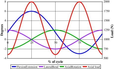
The ISO standard test required application of axial loading, flexion–extension, lateral bending and axial rotation to each of the six actively tested implants. A seventh disc (load-soak control) was tested under only axial loading. The loads and motions used, including the tolerances required by the ISO standard, are summarised in Fig. 1 and Table 1.
Fig. 1.
ISO 18192-1 lumbar TDR wear-testing inputs for 4DOF tests
Table 1.
Summary of ISO18192-1 loads and motions with required tolerances [25]
| DOF | Magnitude | Frequency (Hz) | Tolerances |
|---|---|---|---|
| Axial loading | 600–2,000 N | 2 | ±5% of the maximum load at maxima and minima |
| Flexion/extension | +6°/−3° | 1 | ±0.5° at the minima and maxima |
| Lateral bending | ±2° | 1 | |
| Axial rotation | ±2° | 1 |
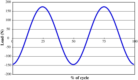
The 5DOF test followed the same procedure as the 4DOF ISO test, except that six new ProDisc-L implants were tested under the ISO standard conditions with an additional AP shear load of +175/−145 N, shown in Fig. 2. These loading data were based upon in vivo studies of the anterior–posterior load during walking [19], simplified to a sinusoidal waveform within the same physiological range with the AP load peaks designed to be coincidental with the axial load peaks. This did lead to a contradiction in that peak anterior shear was coincident with both peak flexion and peak extension, and peak posterior shear was coincident with the neutral position. ISO18192 prescribes flexion–extension frequency to be 1 Hz, yet there are contradictions in the literature suggesting that for most lumbar levels flexion–extension frequency is 2 Hz [19, 26, 27]. With the 5DOF test, the authors wanted to only change one parameter; and so AP shear was chosen to be coincident with the axial load, and not flexion–extension. A seventh disc (load-soak control) was tested under axial loading only.
Fig. 2.
Anterior–posterior shear load input for 5DOF tests
An analysis of variance (ANOVA; SPSS for Windows, SPSS Inc., Chicago, IL) was used to compare the mean wear measurements between the two tests, and to compare the wear rates at each million-cycle time point. The p values obtained were assessed for significance at α = 0.05. In the case of significance, post hoc tests were used to determine the source of significant differences; Levene’s test for homogeneity of variance was used prior to either Scheffe’s (equal variance) or Tamhane’s (unequal variance) post hoc tests.
Results
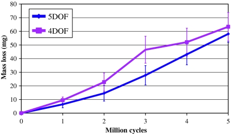
The ISO standard test produced a mean wear mass loss (±standard deviation) of 63.3 ± 10.4 mg, and a mean wear rate of 12.7 ± 2.1 mg/MC, calculated over the full 5 MC test (Fig. 3). The 5DOF test produced a mean wear mass loss equal to 58.0 ± 6.2 mg and an average wear rate of 11.6 ± 1.2 mg/MC. No significant differences were found when comparing between the 4DOF and 5DOF tests, for either wear mass loss (p = 0.67) or mean wear rate (p = 0.78).
Fig. 3.
Mean mass loss for 4DOF and 5DOF ProDisc wear tests at 1 MC intervals, with error bars representing ± standard deviation. Bacterial contamination was evident at 3 MC in the 4DOF test
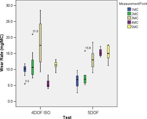
The wear rates for each measurement time point in both tests are summarised in Fig. 4, with the post hoc test results summarised in Tables 2 and 3 for the 4DOF and 5DOF tests, respectively. There was a peak in the wear rate at the 3 MC time point in the 4DOF test, which proved to be significantly different from the other time points. This was coincident with heavy microbial contamination of the lubricant, which may have altered the lubrication properties. The 4 MC wear rate was also significantly different from the 5 MC wear rate. Despite the problems with bacterial contamination, linear regression analysis produced an R2 value of 0.9753. In the 5DOF test, the wear rate increased from 0 to 4 MC, with significance found between 1 MC compared to 3 MC, 4 MC and 5 MC, and 2 MC compared to 4 MC and 5 MC. There were no significant differences between the 3 MC, 4 MC and 5 MC time points, suggesting that steady-state wear had been reached by 5 MC. Linear regression analysis produced an R2 value of 0.97.
Fig. 4.
Box plots of wear rates at each MC time point for the 4DOF ISO test and 5DOF tests, with asterisk indicating outliers that are >± 3SD away from the mean. Bacterial contamination was evident at 3 MC in the 4DOF test
Table 2.
p Values from the comparison of wear rates between each MC measurement point in the 4DOF test using Tamhane’s post hoc test assuming unequal variance
| 1 MC | 2 MC | 3 MC | 4 MC | 5 MC | |
|---|---|---|---|---|---|
| 1 MC | 0.73 | 0.00* | 0.08 | 0.76 | |
| 2 MC | 0.02* | 0.09 | 0.99 | ||
| 3 MC | 0.00* | 0.00* | |||
| 4 MC | 0.00* |
* Significant difference between groups
Table 3.
p Values from the comparison of wear rates between each MC measurement point in the 5DOF test using Scheffe’s post hoc test assuming equal variance
| 1 MC | 2 MC | 3 MC | 4 MC | 5 MC | |
|---|---|---|---|---|---|
| 1 MC | 0.91 | 0.01* | 0.00* | 0.00* | |
| 2 MC | 0.08 | 0.01* | 0.01* | ||
| 3 MC | 0.81 | 0.88 | |||
| 4 MC | 1.00 |
* Significant difference between groups
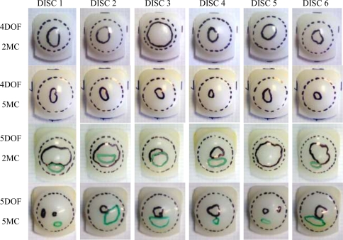
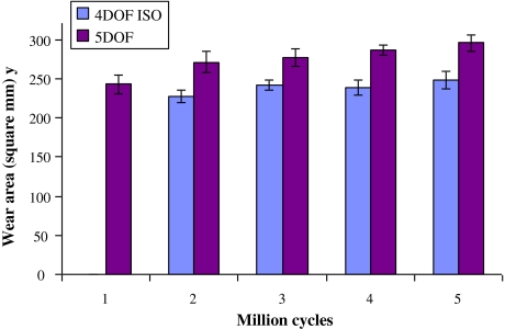
In terms of visible wear scars, Fig. 5, the 4DOF tests showed a large area of contact, evidenced by removal of machining marks and surface deformation, almost covering the whole dome of the disc (dashed black line). These discs also showed areas of damage to the surface that was not characterised by polishing, but by roughening of the surface (solid black line). The 5DOF tested discs showed a larger area of contact compared to 4DOF (p = 0.01), shown in Fig. 6, extending to the anterior dome rim, with a similar areas of surface damage (solid black line) and additional areas of sliding/scratching damage (solid green line) towards the anterior of the disc. The mean AP length of the wear scars increased by a total of 1.5 mm in the 5DOF test, suggesting that the input AP force created minimal translation of the ProDisc. Over time, these areas of surface damage appeared to reduce in size, with the discs effectively becoming more polished, which may be a result of them becoming more conforming as the test progressed.
Fig. 5.
Photographs of the wear scars of each of the six discs for 4DOF tests at 2 MC and 5 MC, and 5DOF tested discs at 2 MC and 5 MC. Areas highlighted are total worn area (dashed black line), roughened surface damage (solid black line) and sliding/scratching damage (solid green line)
Fig. 6.
Total worn area (mean ± standard deviation) for the 4DOF ISO and 5DOF tests, representing the area with removal of machining marks, with all 5DOF areas significantly larger than 4DOF areas (p < 0.05). Wear scar data at 1 MC in the 4DOF test is unavailable
Discussion
This study compared the wear of the ProDisc-L TDR under two different simulation conditions, the first using ISO18192 input conditions (4DOF), and the second using ISO18192 plus an additional AP shear load input (5DOF). Results were analysed for differences in total wear mass loss, wear rate and the surface wear pattern.
In the 4DOF test, wear mass loss was consistent with previously published TDR wear data, showing that the 5DOF simulator utilising only 4DOF produced results of the same magnitude, 10–20 mg/MC, as those simulators currently in use [14, 28]. Differences can arise between simulators, laboratory protocols and users. A recent 4DOF test with the same protocol and in the same laboratory, but performed on a different simulator (of the same design) by a different observer, produced a wear rate of 16.1 ± 1.4, a difference of 25% to the study reported here. It is vital that both testing inputs and criteria are reported accurately and in detail, so that these differences can be identified.
The addition of an anterior–posterior load in the 5DOF tests did not affect the overall wear generated in the ProDisc-L when compared to the 4DOF test. However, there was a distinct difference in the wear pattern between the two tests, suggesting a difference in the wear process. The secondary damage areas identified were characterised by an increase in surface roughness, reducing in size over the course of the test. It is postulated that this may be wear debris that is as yet not completely removed from the surface. Both tests showed increasing polishing over the 5 MC test, suggesting that the implants do have a ‘bedding-in’ period. However, an increasing wear rate was seen in the 5DOF tests, which may be due to an increasing contact area, which was supported by the wear scar measurements. In opposition to classical wear theory (Archard’s wear law) [29], increased contact area has been shown to increase polyethylene wear rates [30], provided that the contact stress is still below the yield stress, which would otherwise lead to fatigue failure. Archard’s law holds true for cases where the asperity contacts deform plastically, such as in metallic contacts. However, in the case of polyethylene, contact asperities deform predominantly elastically, meaning that Archard’s law does not hold true.
The significant differences in wear rates at different measurement time points in each test suggest that 5 MC tests may be too short to quantify and qualify wear behaviour. Further research is necessary to determine a test length that is appropriate to the in vivo condition. Although 5 MC may be sufficient to establish steady-state wear, it would be prudent to continue tests for as long as is practical up to the 10 MC specified by ISO18192-1, or until steady-state wear is evident. It was also recognised that the tests described here have only been performed once, and further detailed reporting of in vitro tests may allow a clearer consensus on this issue.
The current standard ISO18192-1 provides a representative condition given the available biomechanical information, yet there is debate regarding whether the motions in particular are appropriate for a functional spinal unit under physiological conditions. Spinal loads and motions are more difficult to quantify than other joints due to the fact that vertebral recruitment patterns vary significantly from person to person [26]. Without validation against explanted TDR, in vitro wear tests can only give information on how TDR designs perform compared to each other and as yet provide no real indication of how they perform in vivo.
The tests described here used lubricants appropriate for the synovial joints of hip and knee prostheses [31]. Spinal discs are not synovial, and while there is some evidence to suggest a fibrous capsule may form around TDR [32], there is no evidence that the same lubricants are appropriate for TDR wear testing. The testing of hip and knee prostheses has shown wear to be heavily dependent on the lubricant properties, and so validation of the lubricant used in spinal wear tests is necessary to produce clinically relevant results. In vivo the lubricant may be simply interstitial fluid, with a viscosity of 1.25 mPas as opposed to 10 mPas for bovine serum [33], and this must be considered when interpreting TDR wear results. Until there is evidence to the contrary, the use of lubricants common to other joint simulations at least allows comparison with other joint replacements.
Although the amount of polyethylene wear debris generated during wear of TDR is towards the lower range of that generated in metal-on-polyethylene hips, the TDRs are much smaller, as is the potential space within which debris can accumulate. When osteolysis does occur in the spine [9–11], this could affect the stability of the spine and wear debris in close proximity to the spinal cord may cause further problems, particularly if it causes inflammation of these tissues.
The two input conditions described in this study were not greatly dissimilar, so it is unsurprising that quantitative wear showed no significant difference. The slight increase in wear area between 4DOF and 5DOF correlated to only a minor increase in AP displacement of approximately 1.5 mm due to the constrained nature of the ProDisc and therefore the testing conditions between 4DOF and 5DOF area were nearly similar. Increasingly dissimilar inputs are likely to produce increasing differences in wear rates and patterns. Similar testing to this study performed on a less-constrained design, such as the Charité, may have a more dramatic effect on wear, and as such should be investigated further. As it is still not clear what represents ‘normal’ loadings and motions, nor even a ‘normal range’, it is imperative that further parametric studies be carried out along with validation from in vivo studies and explanted components. Further TDR wear simulation (both in vitro and computational) will help the spine community to understand the wear process further and lead to advancements in design.
In conclusion, the tests described here showed similar wear rates to those that have been reported previously. The addition of AP load did not affect wear rates in the case of the ProDisc-L implant, at least up to 5 MC. The AP load input caused a change in the surface wear pattern, something which merits further investigation with improved objective measurement methods. The investigation of TDR wear should be expanded to include all available implants, including metal-on-metal devices, in order to improve device design and to guard against failure due to wear in the future.
Acknowledgments
This work was supported by the National Institutes of Health grant R01-AR052653 as part of a collaboration between the University of Leeds, University of Iowa, and Spine Centre Munich. Professor Fisher, Professor Ingham and Professor Hall receive support from the NHIR Leeds Musculoskeletal Biomedical Research Unit. The ProDisc-L implants were provided by Synthes Spine, Warsaw, Indiana, USA.
Conflict of interest statement Professor Fisher is a Director of BITECIC Ltd and Tissue Regenix Ltd and a paid consultant to DePuy International, a Johnson & Johnson company. Professor Ingham is a shareholder of BITECIC Ltd and a Director of Tissue Regenix Ltd. Professor Brown is a paid consultant to Smith & Nephew Orthopaedics.
References
- 1.Zigler J, Delamarter RB, Bae H, Sachs BL, Rashbaum RF, Ohnmeiss DD, Kanim LEA, Pradhan BB (2005) Lumbar total disc replacement: a 2 to 3 year report from centers in the United States clinical trial for the ProDisc-II prosthesis. In: Spine arthroplasty 5. Global symposium on motion preservation technology. Spine Arthroplasty Society, New York, USA
- 2.Lemaire JP, Skalli W, Lavaste F, Templier A, Mendes F, Diop A, Sauty V, Laloux E. Intervertebral disc prosthesis: results and prospects for the year 2000. Clin Orthop Relat Res. 1997;337:64–76. doi: 10.1097/00003086-199704000-00009. [DOI] [PubMed] [Google Scholar]
- 3.Lee CK, Langrana NA. A review of spinal fusion for degenerative disc disease: need for alternative treatment approach of disc arthroplasty? Spine J. 2004;4(6 Suppl 1):S173–S176. doi: 10.1016/j.spinee.2004.07.002. [DOI] [PubMed] [Google Scholar]
- 4.Fritzell P, Hagg O, Wessberg P, Nordwall A. 2001 Volvo Award winner in clinical studies: Lumbar fusion versus non-surgical treatment for chronic low back pain: a multicenter randomized controlled trial from the Swedish Lumbar Spine Study Group. Spine. 2001;26:2521–2532. doi: 10.1097/00007632-200112010-00002. [DOI] [PubMed] [Google Scholar]
- 5.Zigler J, Parkinson A, Guyer RD, Blumenthal SL, Ohnmeiss DD (2009) Re-operations in lumbar total disc replacement: experience with our first consecutive 800 cases. In: SAS09: Nineth annual global symposium on motion preservation technology, The International Society for the Advancement of Spinal Surgery, London
- 6.Kurtz SM, Lau E, Ianuzzi A, Lanman THMD, Isaza J, Albert T (2009) National Revision Burden for Lumbar Total Disc Arthroplasty in the United States. In: 55th Annual Meeting of the Orthopaedic Research Society, Orthopaedic Research Society, Las Vegas, NV
- 7.Fritzell P, Hagg O, Nordwall A. Complications in lumbar fusion surgery for chronic low back pain: comparison of three surgical techniques used in a prospective randomized study. A report from the Swedish Lumbar Spine Study Group. Eur Spine J. 2003;12:178–189. doi: 10.1007/s00586-002-0493-8. [DOI] [PMC free article] [PubMed] [Google Scholar]
- 8.Lewis G. Polyethylene wear in total hip and knee arthroplasties. J Biomed Mater Res. 1997;38(1):55–75. doi: 10.1002/(SICI)1097-4636(199721)38:1<55::AID-JBM8>3.0.CO;2-G. [DOI] [PubMed] [Google Scholar]
- 9.Hallab NJ, Cunningham BW, Jacobs JJ. Spinal implant debris-induced osteolysis. Spine. 2003;28(20):S125–S138. doi: 10.1097/00007632-200310151-00006. [DOI] [PubMed] [Google Scholar]
- 10.Punt I, Cleutjens JPM, Bruin T, Willems PC, Kurtz SM, Rhijn L, Schurink GWH, Ooij A. Periprosthetic tissue reactions observed at revision of total intervertebral disc arthroplasty. Biomaterials. 2009;30:2079–2084. doi: 10.1016/j.biomaterials.2008.12.071. [DOI] [PubMed] [Google Scholar]
- 11.Devin CJ, Myers TG, Kang JD. Chronic failure of a lumbar total disc replacement with osteolysis. Report of a case with nineteen-year follow-up. J Bone Joint Surg Am. 2008;90(10):2230–2234. doi: 10.2106/JBJS.G.01712. [DOI] [PubMed] [Google Scholar]
- 12.(2008) Implants for surgery—wear of total intevertebral spinal disc prostheses—Part 1: loading and displacement parameters for wear testing and corresponding environmental conditions for test, in BS ISO18192-1
- 13.(2005) Standard guide for functional, kinematic, and wear assessment of total disc prostheses. In: ASTM F 2423-05
- 14.Nechtow W, Hinter M, Bushelow M, Kaddick C (2006) IVD replacement mechanical performance depends strongly on input parameters. In: Orthopaedic Research Society Meeting. Chicago, IL
- 15.Wright TM, Cottrell JM, Punga K, Rawlinson JJ, Gunsallus DL (2006) Retrieval and wear analyses of ProDisc lumbar disc implants. In: Spine arthroplasty 6. Global symposium on Motion preservation technology, Spine Arthroplasty Society, Montreal, Quebec, Canada
- 16.Serhan H, Dooris A, Parsons ML, Ares PJ, Gabriel SM. In vitro wear assessment of the Charite′ Artificial Disc according to ASTM recommendations. Spine. 2006;31(17):1900–1910. doi: 10.1097/01.brs.0000228716.60863.ab. [DOI] [PubMed] [Google Scholar]
- 17.Grupp TM. Biotribological evaluation of artificial disc arthroplasty devices: influence of loading and kinematic patterns during in vitro wear simulation. Eur Spine J. 2009;18:98–108. doi: 10.1007/s00586-008-0840-5. [DOI] [PMC free article] [PubMed] [Google Scholar]
- 18.White AA, Panjabi MM (1990) Clinical biomechanics of the spine. 2nd edn. Lippincott, Philadelphia
- 19.Callaghan JP, Patla AE, McGill SM. Low back three-dimensional joint forces, kinematics, and kinetics during walking. Clin Biomech. 1999;14(3):203–216. doi: 10.1016/S0268-0033(98)00069-2. [DOI] [PubMed] [Google Scholar]
- 20.Kingma I, Staudenmann D, Dienne JH. Trunk muscle activation and associated lumbar spine joint shear force under different levels of external forward force applied to the trunk. J Electromyogr Kinesiol. 2007;17:14–24. doi: 10.1016/j.jelekin.2005.12.001. [DOI] [PubMed] [Google Scholar]
- 21.Metzger MF, Bradford D, Lotz JC (2009) First generation TDR devices do not adequately resist shear in the lumbosacral spine. In: SAS09: Nineth annual global symposium on Motion preservation technology, The International Society for the Advancement of Spinal Surgery, London
- 22.Hall RM, Brown TD, Fisher J, Ingham E, Mendoza SA, Mayer HM. Introduction to lumbar total disc replacement: factors that affect tribological performance. Proc Inst Mech Eng Part J J Eng Tribol. 2006;220:775–786. doi: 10.1243/13506501JET187. [DOI] [Google Scholar]
- 23.Wang A, Polineni VK, Essner A, Stark C, Dumbleton JH (1999) The impact of lubricant protein concentration on the outcome of hip joint simulator testing. In: 45th Annual Meeting of the Orthopaedic Research Society, Orthopaedic Research Society, Anaheim, California
- 24.Vicars R, Fisher J, Heyes N, Birrell R, Hall RM (2007) Verification of a novel spine wear simulator. In: B.O.R. Society (ed) British Orthopaedic Research Society Annual Conference, Manchester, UK
- 25.(2005) Implants for surgery—wear of total intevertebral spinal disc prostheses—part 1: loading and displacement parameters for wear testing and corresponding environmental conditions for tests, in ISO/DIS 18192-1
- 26.Gatton ML, Pearcy MJ. Kinematics and movement sequencing during flexion of the lumbar spine. Clin Biomech. 1999;14(6):376–383. doi: 10.1016/S0268-0033(98)00109-0. [DOI] [PubMed] [Google Scholar]
- 27.Syczewska M, Oberg T, Karlsson D. Segmental movements of the spine during treadmill walking with normal speed. Clin Biomech. 1999;14:384–388. doi: 10.1016/S0268-0033(99)00003-0. [DOI] [PubMed] [Google Scholar]
- 28.Rawlinson JJ, Punga KP, Gunsallus KL, Bartel DL, Wright TM. Wear simulation of the ProDisc-L disc replacement using adaptive finite element analysis. J Neurosurg Spine. 2007;7(2):165–173. doi: 10.3171/SPI-07/08/166. [DOI] [PubMed] [Google Scholar]
- 29.Archard JF. Contact and rubbing of flat surfaces. J Appl Phys. 1953;24:981–988. doi: 10.1063/1.1721448. [DOI] [Google Scholar]
- 30.Kang L, Galvin AL, Brown TD, Fisher J, Jin ZM. Wear simulation of ultra-high molecular weight polyethylene hip implants by incorporating the effects of cross-shear and contact pressure. Proc Inst Mech Eng Part H J Eng Med. 2008;222(7):1049–1064. doi: 10.1243/09544119JEIM431. [DOI] [PubMed] [Google Scholar]
- 31.Wang A, Stark C, Dumbleton JH. Mechanistic and morphological origins of ultra-high weight molecular polyethylene wear debris in total joint replacement. Proc Inst Mech Eng Part H J Eng Med. 1996;210:141–155. doi: 10.1243/PIME_PROC_1996_210_407_02. [DOI] [PubMed] [Google Scholar]
- 32.Bullough PG, DiCarlo EF, Hansraj KK, Neves MC. Pathologic studies of total joint replacement. Orthop Clin North Am. 1988;19(3):611–625. [PubMed] [Google Scholar]
- 33.Shaheen A, Shepherd DET. Lubrication regimes in lumbar total disc arthroplasty. Proc Inst Mech Eng Part H J Eng Med. 2007;221:621–627. doi: 10.1243/09544119JEIM204. [DOI] [PubMed] [Google Scholar]


