Abstract
Magnetic Resonance Imaging (MRI) guided robotic interventions have been introduced in order to advance prostate cancer detection and treatment. To overcome problems of such robotic interventions, we have been developing a pneumatically actuated MRI-compatible modular robotic system for MRI-guided transperineal prostate intervention and its interventional procedure. For system evaluation, a series of experiments have been conducted and this paper reports a needle insertion experiment using prostate phantom and patient mockup trials. The needle insertion experiment resulted in noticeable consistent error in one direction, which we will investigate further. Nonetheless, patient mockup experiences suggest that the modular robotic system and its interventional procedure are well integrated and implemented in clinical environment.
I. Introduction
Prostate cancer is a major health concern in the United States. In 2009, an estimate of 192280 new cases and 27360 deaths are reported, which are the largest number of male cancer (25%) and the second largest cause of cancer death (9%) for men. In the last two decades, however, the death rate is decreasing, which largely reflects improvements in early detection and/or treatment [1]. A typical diagnosis method for prostate cancer is core needle biopsy. Once cancer is found, low-dose-rate (LDR) permanent brachytherapy is commonly performed by implanting a large number (50 to 150) of radioactive seeds into the prostate using needles [2]. The distribution of seeds is important since it should effectively cover suspected volume in order to eradicate cancer with minimal radiation toxicity to healthy tissues.
A. Common Procedure and Emerging MRI
Transrectal ultrasound (TRUS) guidance is the most commonly used navigation method for the prostate biopsy and brachytherapy since the simple method is utilizing real-time imaging at low cost [3]. TRUS-guided biopsy, however, has a poor cancer detection rate of 20% to 30% [4]. In order for greater detection rate, magnetic resonance imaging (MRI) has been sought for the prostate procedures. MRI has high sensitivity for detecting prostate tumor (excellent soft tissue contrast), high spatial resolution, and multi-planar volumetric imaging capabilities [5]. However, closed-bore high-field (1.5T or greater) MRI has not been widely adopted for prostate interventions due to strong magnetic field that requires MRI-compatibility of surgical devices and physical limitation of in-bore access and confined workspace.
A clinical feasibility of MRI-guided prostate biopsy and brachytherapy was demonstrated by D’Amico et al. at the Brigham and Women’s Hospital using a 0.5T open-MRI scanner to plan and monitor transrectal needle placement [6], [7]. The needles were inserted manually using a plastic guide that has a grid of holes similar to the TRUS-guided procedure. Zangos et al. used a transgluteal approach with 0.2T MRI but did not target the tumor foci [8]. Susil et al. reported four cases of transperineal prostate biopsy in a closed-bore scanner, where the patient (MRI table) was moved out of the bore for needle insertion, then, placed back into the bore for confirmation scan [9]. Beyersdorff et al. performed transrectal biopsy in a 1.5T MRI scanner with a passive articulated needle guide [10].
B. MRI-guided Robotic Interventions
Early robotically assisted (guided) instrument placement in MRI has been investigated in neurosurgery [11] and percutaneous interventions [12], [13]. Chinzei et al. developed a general purpose robotic assistant for open-MRI [14] that was subsequently adapted for transperineal intraprostatic needle placement [15]. Krieger et al. presented a 2 degrees of freedom (DOF) manually manipulated mechanical device to guide transrectal prostate biopsy [16]. In recent years, a number of MR-compatible motor technologies have been introduced: Stoianovici et al. developed a fully MRI-compatible pneumatic stepper motor called PneuStep [17], Elhawary et al. presented an air motor for limb localization [18], and Suzuki et al. introduced a stepper motor that uses the scanner’s magnetic field as a driving force [19].
More recent robot developments include pneumatic stepping motors on a light needle puncture robot [20], the Innomotion pneumatic robot for percutaneous interventions [21], haptic interfaces for functional MRI (fMRI) [22], a fully automated prostate brachytherapy seed placement system [23], a pneumatically/hydraulically driven transperineal robot for gold marker implantation [24], and a piezo-ceramic motor driven transrectal biopsy robot [25].
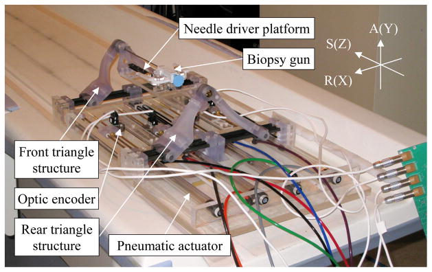
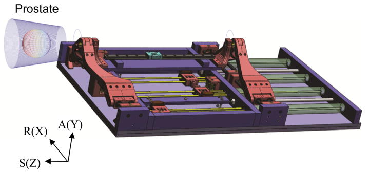
Using low friction pneumatic actuators, we have developed a high field (3T) MRI-guided prostate intervention system for transperineal needle placement procedures [26]. Fig. 1 shows the 4-DOF pneumatically actuated robot that provides needle insertion angle guide and a platform for needle driver. The robot development previously focused on manipulator details i.e. pneumatic actuator control, workspace optimized design and targeting functions, since other system components were being developed at the time, leaving overall system integration and procedural description for the present study.
Fig. 1.
Pneumatically actuated 4-DOF robot for MRI-guided transperineal prostate needle placement (RAS: scanner coordinate, XYZ: manipulator coordinate).
With our latest development activities, this paper reports the robotic system focusing on operational description of the system, which helps understand the purpose and intended outcome of the development. The following section (Section II) identifies overall system architecture and interventional procedure. Needle placement manipulator (4-DOF robot) descriptions that contain key system parameters are explained in Section III. Section IV describes preliminary evaluation: prostate phantom targeting experiment and patient mockup experiences, followed by conclusion and future work (Section V).
II. System Architecture and Procedure
The integration of MRI and robotic assistant has been significantly advancing prostate interventional procedures. However, such procedures are highly robot-dependant, often leaving no contingent method that still benefits from the MRI in case of robot failure and/or when manual needle insertion is required. In order to maximize both benefits, we have developed a modular prostate intervention system that can be utilized for both robotic and manual (using a needle guide template – similar to TRUS template) procedures with a single registration. The modular approach can be achieved by placing a stationary frame and a number of predefined mechanical attachment positions on rigidly connected base board for removable system components.
A. System Components and Modular Structure
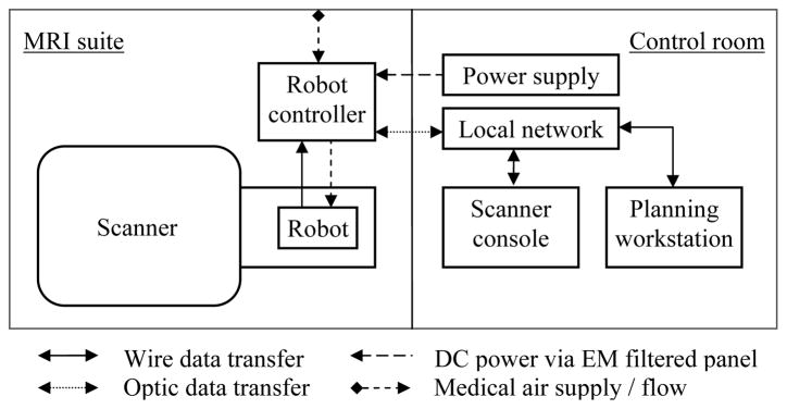
Overall interventional system consists of scanner, robot, controller, scanner console and planning software. Fig. 2 illustrates a diagram of system components and information flow. In order to minimize electro-magnetic interference, the controller is powered through the grounded patch panel, which is designed for such connections, and control data communication is enabled via fiber-optic Ethernet. A local network connects the scanner console, planning software workstation (a laptop) and robot controller.
Fig. 2.
Diagram of system components and information flow.
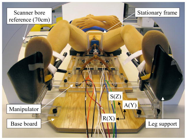
The robot consists of 1) base board, where patient is located, 2) stationary frame, which clears needle insertion area, 3) registration block, 4) manual needle insertion template, 5) manipulator, and 6) leg support, shown as Fig. 3. The registration block, template and manipulator can be placed at mechanically predefined positions on the board so that they can be removed and accurately repositioned without re-registration if the patient (prostate target) remains at the same position relative to the stationary frame and board. In order to accommodate subjective (due to various prostate positions – vertically in supine position) targeting workspace with the workspace-optimized manipulator, a vertical spacer i.e. a simple MRI-compatible plate with known thickness, can be placed under the manipulator. A pair of adjustable leg support is used for optimal positioning and comfort.
Fig. 3.
Picture of modular robot system showing base board, stationary frame, manipulator and leg support.
B. Interventional Procedure: Operational Workflow
Needle driver has not been developed so that manual needle insertion procedure is currently scripted as listed (1) to (7) with sub-tasks in order, for prostate biopsy and brachytherapy. Usually, patient needs to be outside bore for needle insertion. In short bore, however, surgeon may be able to perform needle insertion while patient is in scanning position. Conventional clinical preparation and secondary procedures are omitted in the robotic procedure script.
Manipulator and communication setup: a) assemble sterilized manipulator parts (not on scanner table). b) place controller and connect power, optic cable and air. c) connect scanner, planning software workstation and controller using local network. d) test run manipulator and ready for command at home position.
Robot stationary module and patient setup: a) setup robot stationary modules. b) locate patient and leg support. c) adjust patient position to ensure: perineum is close to the stationary frame, enough perineum access area, enough under-leg space for manipulator slide in-and-out. d) prepare perineum (iodine etc). e) Place registration block for registration scan. f) connect imaging coils and check bore clearance.
Preoperative T1 imaging: a) slide patient into scanner. b) acquire localizer images: reposition patient as necessary. c) acquire calibration images (registration block images). d) transfer (or automatic push via network) images to software workstation. e) register robot position (predefined relative to registration block) in scanner coordinate.
Preoperative T2 imaging and planning: a) acquire pre-procedural images. b) transfer T2 images to software workstation. c) target planning (by clinician). d) place target(s) in the software and provide reachable insertion angle (visualize kinematic back projection volume from target). e) determine insertion angle (by clinician).
Robot ready: a) slide patient table out and remove registration block. b) if necessary, place a vertical spacer to raise manipulator. c) place manipulator and secure.
Needle placement and insertion: a) load a needle and set predefined axial home position (e.g. set 4th tick from needle tip at entrance of brass tube). b) software workstation sends first position command to manipulator. c) manually insert needle to planned depth. d) fire biopsy gun/drop brachytherapy seeds. e) confirmation scan if necessary. f) remove needle and repeat from a).
Contingent procedure using needle guide template: (can be performed immediately during steps 5) and 6)). a) remove manipulator. b) place needle guide template at predefined position. c) switch software to template target planning. d) identify insertion hole. e) manually insert needle and repeat from d).
III. Needle Placement Manipulator
To optimize workspace, a parallel kinematic structure manipulator that can accommodate commonly used biopsy and brachytherapy needles, has been designed [26]. Currently the manipulator provides needle angle guide only and insertion module can be attached. A haptic feedback enabled needle driver that can be attached onto the manipulator is being developed in parallel [27]. Scanner’s RAS coordinate system (Right-left, Anterior-posterior and Superior-inferior) is used for targeting, which is equivalent of manipulator’s X, Y and Z respectively.
A. Mechanism and Workspace
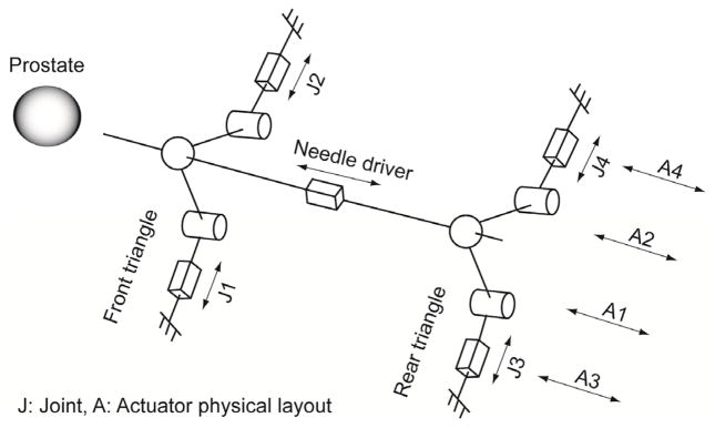
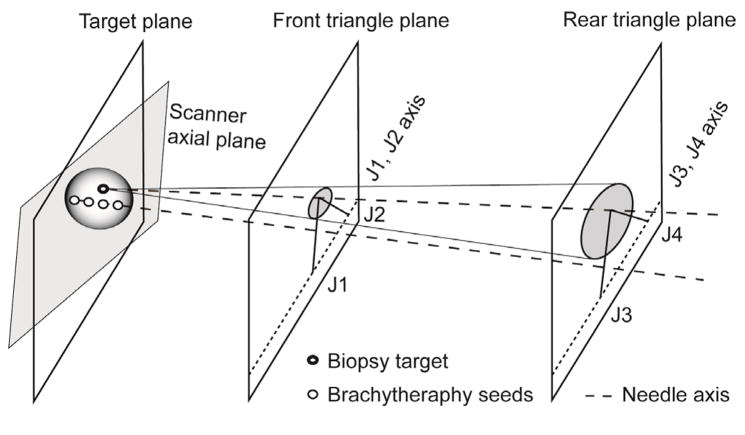
The manipulator has two identical triangular positioning mechanism at two axial (to scanner) planes, which are connected by needle insertion platform in between. Fig 4 illustrates kinematics equivalent diagram of the manipulator. Due to narrow MRI table and low ‘under-leg’ space, four pneumatic actuators are located axially on the same plane shown in Fig. 1. Actuator’s axial positioning is transmitted laterally and the combination of the lateral positioning forms the front and rear triangle. Subsequently, mechanically connecting the triangle tips (ball joint connection) creates the needle insertion axis, resulting in a 4-DOF angle guide.
Fig. 4.
Kinematic diagram and actuator layout.
The 4-DOF manipulation provides a cone shape workspace (seen from top or side, not 3D workspace). The tip of the cone located at the middle of two triangle structure planes and project (by needle insertion) superiorly. Fig. 5 shows a mathematical plot of manipulator workspace i.e. reachable needle tip volume (the 3D workspace view is simplified for prostate coverage, true axial workspace is illustrated in [26]). If necessary, the workspace can be shifted vertically by inserting a spacer as described in Section II. A.
Fig. 5.
Manipulator workspace i.e. reachable needle tip positions (50 mm diameter sphere represents prostate position and size).
B. Target Planning and Positioning
Actuator and Cartesian level position control of the manipulator are described in [26], which is run by previously developed piezoelectric servo valve equipped pneumatic controller [28]. For target planning, a customized graphical user interface (GUI) specially designed for the prostate intervention is used as described in [29]. In order to position the manipulator, an inverse kinematic solution is required. However, a point target creates a kinematically achievable angle volume shown as Fig. 6. This can be an advantage since clinician is able to choose a safer and least invasive insertion angle concerning anatomical avoidance such as pubic arch and urethra.
Fig. 6.
Diagram of inverse kinematic solution for a biopsy target and a series of brachytherapy seeds distribution planning.
In planning, once target is determined, possible inverse kinematic solution (workspace limit) can be visualized on the planning software. Then, clinician determines a suitable insertion angle within the solution by visually moving the needle axis around prostate volume. Once target position and insertion angle is determined i.e. target point and its projection are given, the intersecting points of the projection and each triangle plane are used as an inverse kinematic solution. In other words, the inverse kinematic solution can be obtained from the planning software without separate computing. Fig. 6 illustrates the inverse kinematic solution.
For brachytherapy procedure, the targeting method can be particularly useful since seed distribution can be planned along the needle insertion axis. Both target planning procedures can be summarized as:
Target planning for biopsy: a) pick a target, b) visualize possible insertion angle, c) determine insertion angle (clinician), d) obtain front and rear triangle plane intersecting points, e) send position command.
Target planning for brachytherapy: a) pick target volume, b) visualize possible seeds distribution, c) determine number of insertion and angle (clinician), d) set first insertion angle and distribution plan, e) obtain front and rear triangle plane intersecting points, f) send position command.
IV. Preliminary Evaluation
In order to evaluate the system, four preliminary tests were designed: 1) signal-to-noise ratio (SNR) test for MRI compatibility (EM noise effect concerning image quality), 2) manipulator positioning accuracy and repeatability test, 3) manual needle insertion experiment using prostate phantom, 4) mockup experiences for system integration and procedural feasibility. First two tests were reported in [30] and [26] respectively with satisfying results.
A. Prostate Phantom Trial
A needle insertion experiment was conducted to test the robotic prostate intervention. Ultrasound prostate phantom (Model 053, CIRS) was set as target in 3T GE Excite HD (GE Healthcare) scanner and a biopsy needle was used for the insertion. After registration, 24 random targets (within prostate region in the phantom) were chosen from single axial plane (to eliminate manual insertion error) using the planning software. Fig. 8 shows a screenshot of the planning and navigation software.
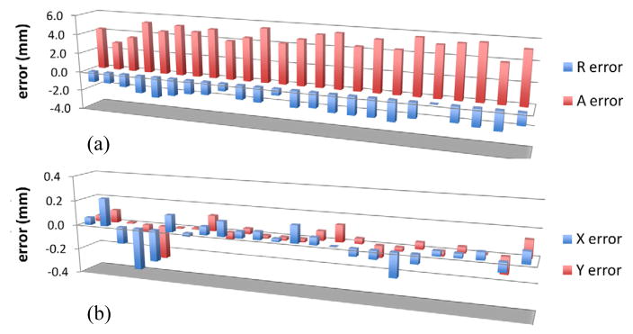
Fig. 8.
Plot of a) needle positioning error and b) manipulator control error in axial plane.
A confirmation image was obtained after each insertion and controller position error was also recorded. From each scan, needle void position was obtained and position error was calculated from planning software’s target position. Fig. 8a) shows the needle insertion error. The maximum needle position error of 5.83 mm was observed in anterior (+Y in manipulator coordinate) direction. An average of 5 mm error with 0.7 mm standard deviation was calculated. Whereas, manipulator control error (difference between command position and actually achieved position) remained within 0.4 mm throughout all insertions with an average error of 0.3 mm. Fig. 8b) shows the manipulator control error. As shown in the plot Fig. 8a), the needle position error values are significantly high compared to the control error and also show consistency in error value and direction. It seems that systematic error e.g. registration error, incorrect offset value, incorrect kinematic constant value, exists in the system, which needs to be identified and re-calibrated.
Another suspected error component is bending of the needle during initial punctuation. When inserting the needle, phantom’s entry surface was elastically deformed by the needle tip creating relatively large reaction force. If the reaction force is not axially uniform e.g. when inserting near the boundary of puncturable surface area, insertion and entry surface is not perpendicular, and/or phantom is being slightly moved non-axially during insertion, it could create needle bending at the entry and likely remains as a directional pressure after the punctuation. In the test, a degree of anterior direction reaction force was observed during punctuation, which could have contributed to the large anterior direction needle positioning error. Clinically, this error component seems less considerable. However, it suggests that non-axial tissue tension or pressure around perineum should be minimized to prevent possible needle bending.
B. Patient Mockup Experiences
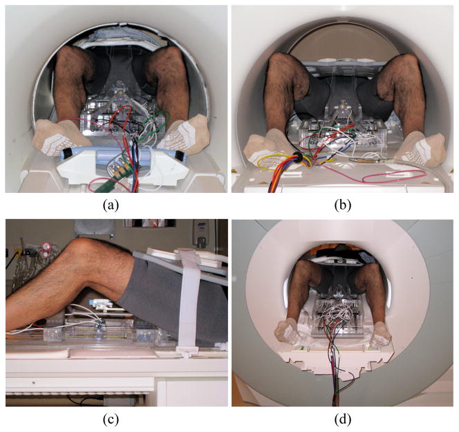
In order to observe problems and to optimize the system and interventional procedure for clinical implementation, patient mockup trials were conducted. The interventional procedure described in Section II. B was performed in two MRI facilities: 60 cm bore 3T GE Excite HD (GE Healthcare) and 70 cm bore Siemens Magnetom Verio (Siemens AG). A human subject participated was for physical occupation and positioning purpose - no MRI scan or needle insertion was conducted. Fig. 9 shows photographs of patient mockup setups. Major observations from the mockup experiences can be summarized:
Fig. 9.
Photographs of patient mockup setup: a) GE axial view, b) Siemens axial view, c) Siemens lateral view and Siemens rear bore opening view with ‘feet-first supine’ patient position (in the pictures, stationary frame are early prototype and no leg support was used. the latest system components can be seen in the Fig. 3).
On-site system setup: depending upon patient transport method i.e. mobile table that can be docked to scanner or transferring patient onto permanently attached scanner table, the system needs to be prepared accordingly. A mobile air compressor and hospital installed compressed air supply were used for pneumatic power source in the GE and Siemens suite respectively. No functional difference was observed.
System communication: currently simple command and report communication is running between control PC and planning software workstation. However, full access to control PC was often required for safety and contingency.
Physical interference: the mockup setup fitted into both 60cm and 70cm bore shown in Fig. 9. In the smaller bore, however, collision between imaging coil and the bore was observed during table insertion. A bore-shape protection that can cover around crowded area on the table might prevent such a problem.
Other observations: the interventional procedure was designed based on ‘head-first supine’ patient position. However, since table body (after table top is slid into bore) remains occupying space, it becomes an obstacle. As an alternative, ‘feet-first supine’ (clinician can access from opening of the bore) was tried to check feasibility and it seemed to provide less obstruction and easier access to the surgical volume.
V. Conclusion and Future work
In order to evaluate a pneumatically actuated robotic system for MRI-guided prostate needle replacement, a needle insertion experiment using prostate phantom and patient mockup procedures have been conducted. The needle insertion experiment resulted in noticeable position error in anterior direction, whereas manipulator control error was almost ignorable. Incorrect control value, registration error and needle bending during punctuation were thought as probable causes. Mechanical and registration calibration will quantify and minimize such problems. A small number of modification and optimization items were identified from the mockup experiences. However, overall robotic system and its interventional procedure seemed well integrated and implemented to on-site environment without major issues. Optimizing clinician’s access space by ‘feet-first supine’ patient positioning can be an interesting approach. Partial sterilization and on-site assembly is current sterilization plan for the intervention prototype. However, more efficient sterilization method will be required.
Fig. 7.
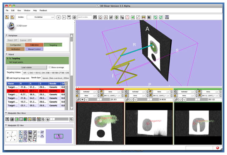
A screenshot of 3D Slicer based planning and navigation software [29], which communicates with robot control software using a network communication protocol, OpenIGTLink [31].
Acknowledgments
This work is supported by National Institute of Health Grants: 1R01CA111288, 5P01CA067165 and 5U41RR019703.
Contributor Information
Sang-Eun Song, National Science Foundation Engineering Research Center for Computer-Integrated Surgical System and Technology, The Johns Hopkins University, Baltimore, MD, US.
Nathan Cho, National Science Foundation Engineering Research Center for Computer-Integrated Surgical System and Technology, The Johns Hopkins University, Baltimore, MD, US.
Junichi Tokuda, National Center for Image-Guided Therapy, Brigham and Women’s Hospital, Harvard Medical School, Boston, MA, US.
Nobuhiko Hata, National Center for Image-Guided Therapy, Brigham and Women’s Hospital, Harvard Medical School, Boston, MA, US.
Clare Tempany, National Center for Image-Guided Therapy, Brigham and Women’s Hospital, Harvard Medical School, Boston, MA, US.
Gabor Fichtinger, School of Computing, Queen’s University, Kingston, Ontario, Canada.
Iulian Iordachita, National Science Foundation Engineering Research Center for Computer-Integrated Surgical System and Technology, The Johns Hopkins University, Baltimore, MD, US.
References
- 1.Jemal A, Siegel R, Ward E, Hao Y, Xu J, Thun M. Cancer Statistics, 2009. CA Cancer J Clin. 2009;59:225–249. doi: 10.3322/caac.20006. [DOI] [PubMed] [Google Scholar]
- 2.Blasko J, Mate T, Sylvester J, Grimm P, Cavanagh W. Brachytherapy for carcinoma of the prostate. Semin Radiat Oncol. 2002;12(1):81–94. doi: 10.1053/srao.2002.28667. [DOI] [PubMed] [Google Scholar]
- 3.Presti J., Jr Prostate cancer:Assessment of risk using digital rectal examination, tumor grade, prostate-specific antigen, and systematic biopsy. Radiol Clin North Amer. 2000;38(1):49–58. doi: 10.1016/s0033-8389(05)70149-4. [DOI] [PubMed] [Google Scholar]
- 4.Terris M, Wallen E, Stamey T. Comparison of mid-lobe versus lateral systematic sextant biopsies in detection of prostate cancer. Urol Int. 1997;59:239–242. doi: 10.1159/000283071. [DOI] [PubMed] [Google Scholar]
- 5.Yu K, Hricak H. Imaging prostate cancer. Radiol Clin North Am. 2000;38(1):59–85. doi: 10.1016/s0033-8389(05)70150-0. [DOI] [PubMed] [Google Scholar]
- 6.D’Amico A, Cormack R, Tempany C, Kumar S, Topulos G, Kooy H, Coleman C. Real-time magnetic resonance image guided interstitial brachytherapy in the treatment of select patients with clinically localized prostate cancer. Int J Radiation Oncol. 1998 Oct;42:507–515. doi: 10.1016/s0360-3016(98)00271-5. [DOI] [PubMed] [Google Scholar]
- 7.D’Amico A, Tempany C, Cormack R, Hata N, Jinzaki M, Tuncali K, Weinstein M, Richie J. Transperineal magnetic resonance image guided prostate biopsy. J Urol. 2000;164(2):385–387. [PubMed] [Google Scholar]
- 8.Zangos S, Eichler K, Engelmann K, Ahmed M, Dettmer S, Herzog C, Pegios W, Wetter A, Lehnert T, Mack M, Vogl T. MRguided transgluteal biopsies with an open low-field system in patients with clinically suspected prostate cancer: Technique and preliminary results. Eur Radiol. 2005;15(1):174–182. doi: 10.1007/s00330-004-2458-2. [DOI] [PubMed] [Google Scholar]
- 9.Susil R, Camphausen K, Choyke P, McVeigh E, Gustafson G, Ning H, Miller R, Atalar E, Coleman C, Ménard C. System for prostate brachytherapy and biopsy in a standard 1.5 T MRI scanner. Magn Resonance Med. 2004;52:683–6873. doi: 10.1002/mrm.20138. [DOI] [PMC free article] [PubMed] [Google Scholar]
- 10.Beyersdorff D, Winkel A, Hamm B, Lenk S, Loening S, Taupitz M. MR imaging-guided prostate biopsy with a closed MR unit at 1.5 T. Radiology. 2005;234:576–581. doi: 10.1148/radiol.2342031887. [DOI] [PubMed] [Google Scholar]
- 11.Masamune K, Kobayashi E, Masutani Y, Suzuki M, Dohi T, Iseki H, Takakura K. Development of an MRI-compatible needle insertion manipulator for stereotactic neurosurgery. J Image Guid Surg. 1995;1(4):242–248. doi: 10.1002/(SICI)1522-712X(1995)1:4<242::AID-IGS7>3.0.CO;2-A. [DOI] [PubMed] [Google Scholar]
- 12.Felden A, Vagner J, Hinz A, Fischer H, Pfleiderer S, Reichenbach J, Kaiser W. ROBITOM-robot for biopsy and therapy of the mamma. Biomed Tech (Berl) 2002;47(Suppl 1 Pt 1):2–5. doi: 10.1515/bmte.2002.47.s1a.2. [DOI] [PubMed] [Google Scholar]
- 13.Hempel E, Fischer H, Gumb L, Höhn T, Krause H, Voges U, Breitwieser H, Gutmann B, Durke J, Bock M, Melzer A. An MRI compatible surgical robot for precise radiological interventions. CAS. 2003 Apr;8(4):180–191. doi: 10.3109/10929080309146052. [DOI] [PubMed] [Google Scholar]
- 14.Chinzei K, Hata N, Jolesz F, Kikinis R. MR compatible surgical assist robot: System integration and preliminary feasibility study. MICCAI. 2000 Oct;1935:921–933. [Google Scholar]
- 15.DiMaio S, Pieper S, Chinzei K, Fichtinger G, Tempany C, Kikinis R. Robot assisted percutaneous intervention in open-MRI. Proc MRI Symp. 2004:155. [Google Scholar]
- 16.Krieger A, Susil R, Menard C, Coleman J, Fichtinger G, Atalar E, Whitcomb L. Design of a novel MRI compatible manipulator for image guided prostate interventions. IEEE Trans Biomed Eng. 2005 Feb;52(2):306–313. doi: 10.1109/TBME.2004.840497. [DOI] [PMC free article] [PubMed] [Google Scholar]
- 17.Stoianovici D, Patriciu A, Petrisor D, Mazilu D, Kavoussi L. A new type of motor: Pneumatic step motor. IEEE/ASME Trans Mechatron. 2007 Feb;12(1):98–106. doi: 10.1109/TMECH.2006.886258. [DOI] [PMC free article] [PubMed] [Google Scholar]
- 18.Elhawary H, Zivanovic A, Rea M, Tse Z, McRobbie D, Young I, Paley B, Lamprth M. A MR compatible mechatronic system to facilitate magic angle experiments in vivo. Proc. Mid. Image Comput. Comput.-Assisted Interv. Conf. (MICCAI); Nov. 2007; pp. 604–611. [DOI] [PubMed] [Google Scholar]
- 19.Suzuki T, Liao H, Kobayashi E, Sakuma I. Ultrasonic motor driving method for EMI-free image in MR image-guided surgical robotic system. Proc. IEEE Int. Conf. Intell. Robots Syst. (IROS); Oct. 2007; pp. 522–527. [Google Scholar]
- 20.Taillant E, Avila-Vilchis J, Allegrini C, Bricault I, Cinquin P. CT and MR compatible light puncture robot: Architectural design and first experiments. Proc. Mid. Image Comput. Comput.-Assisted Interv. Conf. (MICCAI); 2004. pp. 145–152. [Google Scholar]
- 21.Melzer A, Gutmann B, Remmele T, Wolf R, Lukoscheck A, Bock M, Bardenheuer H, Fischer H. Innomotion for percutaneous image-guided interventions. 2008 May–June;27:66–73. doi: 10.1109/EMB.2007.910274. [DOI] [PubMed]
- 22.Gassert R, Moser R, Burdet E, Bleuler H. MRI/fMRI-compatible robotic system with force feedback for interaction with human motion. T Mech. 2006 Apr;11(2):216–224. [Google Scholar]
- 23.Stoianovici D, Song D, Petrisor D, Ursu D, Mazilu D, Mutener M, Schar M, Patriciu A. ‘MRI Stealth’ robot for prostate interventions. Minim Invasive Ther Allied Technol. 2007 Jul;16(4):241–248. doi: 10.1080/13645700701520735. [DOI] [PMC free article] [PubMed] [Google Scholar]
- 24.Bosch M, Moman M, Vulpen M, Battermann J, Duiveman E, Schelven L, Leeuw H, Lagendijk J, Moerland M. MRI-guided robotic system for transperineal prostate interventions: proof of principle. Phys Med Biol. 2010;55(5):33–40. doi: 10.1088/0031-9155/55/5/N02. [DOI] [PubMed] [Google Scholar]
- 25.Elhawary H, Tse Z, Rea M, Zivanovic A, Davies B, Besant C, de Souza N, McRobbie D, Young I, Lamperth M. Robotic System for Transrectal Biopsy of the Prostate: Real-Time Guidance Under MRI. Engineering in Medicine and Biology Magazine, IEEE. 2010 March–April;29(2):78–86. doi: 10.1109/MEMB.2009.935709. [DOI] [PubMed] [Google Scholar]
- 26.Song S, Cho N, Ficsher G, Hata N, Tempany C, Fichtinger G, Iordachita I. Development of a Pneumatic Robot for MRI-guided Transperineal Prostate Biopsy and Brachytherapy: New Approaches. Proc. IEEE Int. Conf. Robot. Autom. Anchorage; USA. 2010. [DOI] [PMC free article] [PubMed] [Google Scholar]
- 27.Su H, Fischer G. A 3-Axis Optical Force/Torque Sensor for Prostate Needle Placement in Magnetic Resonance Imaging Environments. 2nd Annual IEEE International Conference on Technologies for Practical Robot Applications - TePRA 2009; Woburn, Massachusetts. November 2009. [Google Scholar]
- 28.Fischer GS, Iordachita I, Csoma C, Tokuda J, Dimaio SP, Tempany CM, Hata N, Fichtinger G. Mri-compatible pneumatic robot for transperineal prostate needle placement. Mechatronics, IEEE/ASME Transactions on. 2008;13(3):295–305. doi: 10.1109/TMECH.2008.924044. [DOI] [PMC free article] [PubMed] [Google Scholar]
- 29.Tokuda J, Fischer G, DiMaio S, Gobbi D, Csoma C, Mewes P, Fichtinger G, Tempany C, Hata N. Integrated navigation and control software system for MRI-guided robotic prostate interventions. Comput Med Imaging Graph. 2010;34(1):3–8. doi: 10.1016/j.compmedimag.2009.07.004. [DOI] [PMC free article] [PubMed] [Google Scholar]
- 30.Song S, Cho N, Tokuda J, Hata N, Tempany C, Fichtinger G, Iordachita I. MRI compatibility study of a pneumatically actuated robotic system for transperineal prostate needle placement. Computer Assisted Radiology and Surgery (CARS ‘2010); Proceedings of the 24th International Congress and Exhibition; Geneva, Switzerland. June 23–26, 2010. [Google Scholar]
- 31.Tokuda J, Fischer G, Papademetris X, Yaniv Z, Ibanez L, Cheng P, Liu H, Blevins J, Arata J, Golby A, Kapur T, Pieper S, Burdette E, Fichtinger G, Tempany C, Hata N. OpenIGTLink: an open network protocol for image-guided therapy environment. Int J Med Robotics Comput Assist Surg. 2009;5(4):423–434. doi: 10.1002/rcs.274. [DOI] [PMC free article] [PubMed] [Google Scholar]


