Abstract
We have developed a combinatorial method for determining optimum tissue scaffold composition for several X-ray imaging techniques. X-ray radiography and X-ray microcomputed tomography enable non-invasive imaging of implants in vivo and in vitro. However, highly porous polymeric scaffolds do not always possess sufficient X-ray contrast and are therefore difficult to image with X-ray-based techniques. Incorporation of high radiocontrast atoms, such as iodine, into the polymer structure improves X-ray radiopacity but also affects physicochemical properties and material performance. Thus, we have developed a combinatorial library approach to efficiently determine the minimum amount of contrast agent necessary for X-ray-based imaging. The combinatorial approach is demonstrated in a polymer blend scaffold system where X-ray imaging of poly(desaminotyrosyl-tyrosine ethyl ester carbonate) (pDTEc) scaffolds is improved through a controlled composition variation with an iodinated-pDTEc analog (pI2DTEc). The results show that pDTEc scaffolds must include at least 9%, 16%, 38% or 46% pI2DTEc (by mass) to enable effective imaging by microradiography, dental radiography, dental radiography through 0.75 cm of muscle tissue or micro-computed tomography, respectively. Only two scaffold libraries were required to determine these minimum pI2DTEc percentages required for X-ray imaging, which demonstrates the efficiency of this new combinatorial approach for optimizing scaffold formulations.
Keywords: Combinatorial library, Polycarbonate, Scaffolds, Radiopacity, X-ray microcomputed tomography, X-ray radiography
1. Introduction
The ability to image radiopaque medical implants in vivo with X-ray radiography enables clinicians to conveniently, inexpensively and non-invasively monitor implant performance, wound healing and regeneration. In addition, the internal microstructure of radiopaque implants can be analyzed in vitro with X-ray microcomputed tomography (μCT). However, highly porous tissue engineering scaffolds made from polymers such as PDLLA [poly(d,l-lactic acid)] or pDTEc [poly(desaminotyrosyl-tyrosine ethyl ester carbonate)] do not possess high X-ray contrast and can yield poorly resolved images. The radiopacity of conventional polymers is similar to soft tissue since both are composed primarily of hydrogen, oxygen, nitrogen and carbon. Material X-ray contrast can be improved by increasing material electron density through addition of heavy atoms such as barium, bismuth or iodine [1].
Approaches for adding heavy atoms include: (1) physical mixture of salts, such as addition of barium sulfate to poly(methylmethacrylate) (PMMA) [2] or poly(d,l-lactic acid) [3], (2) blends with organic compounds, such as blending triphenyl bismuth with PMMA [4], and (3) covalent linkage of heavy atoms to the polymer backbone [5], such as iodinating pDTEc to yield pI2DTEc [6,7]. Each approach has its own advantages and disadvantages (reviewed in Ref. [1]). One common problem is that the inclusion of radiocontrast agents will affect physicochemical properties, and, thus, performance of the implant [1–4]. In order to minimize physicochemical changes, it would be advantageous to determine the minimum amount of radiocontrast agent required to impart radiopacity to the implant. Thus, we have developed a combinatorial approach for screening polymeric tissue scaffolds to determine the amount of radiocontrast agent required for effective imaging by common X-ray techniques.
Combinatorial methods can lower the cost of experimentation through fabrication of miniaturized libraries which enable accelerated testing of many specimens and reduce the amount of time and material required for experiments [8]. They have been applied extensively in pharmaceutical research [9,10] and their application in biomaterials research is also becoming widespread [11–15]. The combinatorial approach developed herein is designed for characterizing and optimizing the radiopacity of tissue engineering scaffolds since these constructs constitute a central dogma in the field of tissue engineering [16]. The basic premise of a tissue scaffold is a highly porous, degradable, biocompatible construct that promotes the formation of a desirable tissue by providing a 3D template for cell adhesion, differentiation and tissue generation [17].
A tyrosine-derived polycarbonate polymer system was used to demonstrate the combinatorial approach for screening scaffold radiopacity. Tyrosine-derived polycarbonates are a biodegradable, biocompatible class of polymers being developed for tissue engineering applications [6,15,18]. For the current study, the radiopacity of pDTEc was enhanced through a controlled blending with its iodinated analog, pI2DTEc (Fig. 1a,b). Although the toxicity of an iodinated, resorbable biomaterial is a concern, preliminary results injecting iodinated, resorbable polyesters into rabbits for imaging by computed tomography showed no adverse affects [5]. In addition, a fully resorbable coronary stent made from a pI2DTEc derivative is currently in human clinical trials (Reva Medical, Inc., San Diego, CA, http://www.teamreva.com). Thus degradable, radiopaque polymers such as pI2DTEc are being considered for use as implantable biomaterials. A two-syringe pump system was used to fabricate spatially resolved compositional scaffold libraries of pDTEc and pI2DTEc [19], the libraries were imaged by several common X-ray imaging techniques and images were analyzed to determine the minimum amount of pI2DTEc required for effective imaging. These results demonstrate how combinatorial methods can efficiently identify scaffold formulations that contain the minimum amount of radiocontrast agent necessary for effective imaging by X-ray-based techniques.
Fig. 1.
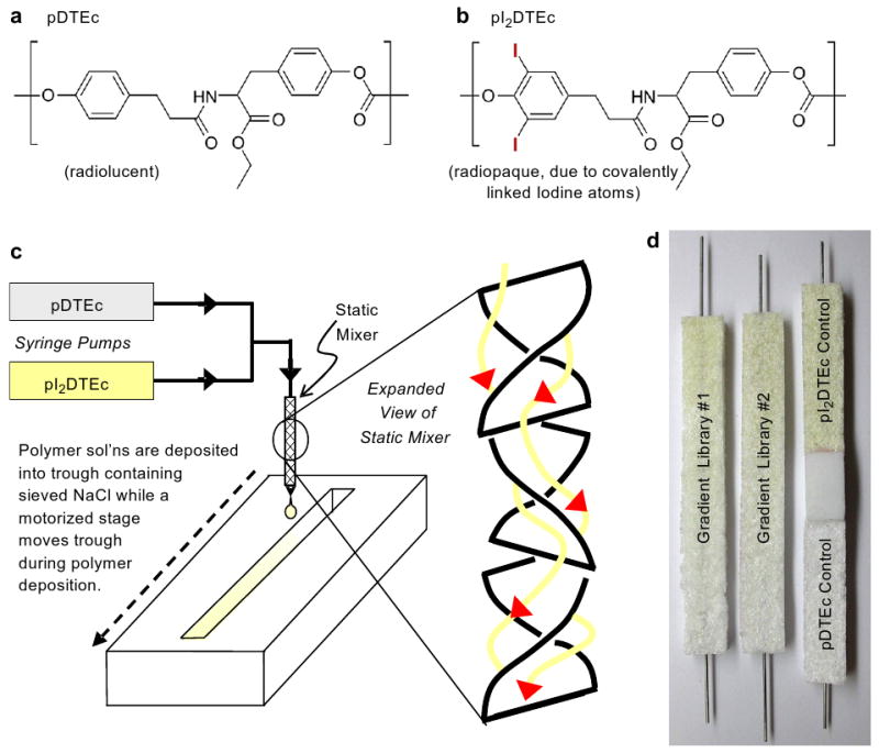
(a) pDTEc structure. (b) pI2DTEc structure. (c) Fabrication of pDTEc/pI2DTEc gradient scaffold library. (d) Two libraries are shown on left and control scaffolds are shown on right. pI2DTEc has a yellowish color.
2. Materials and methods
2.1. Gradient scaffold library fabrication
Combinatorial scaffold libraries were fabricated from pDTEc (185,000 weight averaged molecular weight (Mw); 1.8 polydispersity index (PDI)) and pI2DTEc (294,000 Mw; 1.8 PDI) (Fig. 1a,b) synthesized as described [6,18] using a novel syringe-pump system (Fig. 1c) [19]. For library fabrication, solutions of pDTEc and pI2DTEc (1 g/10 mL dioxane) were placed in opposing syringe pumps, brought together at a T-junction and mixed in a static mixer. The pumps were programmed so that the effluent from the static mixer changed from pI2DTEc-rich to pDTEc-rich over time. The effluent from the mixer was deposited into a teflon trough (75 mm long × 8 mm wide × 6 mm deep) containing 4.3 g of sieved NaCl (250–425 μm in dia.). A stainless steel wire was incorporated lengthwise into the troughs to facilitate handling. A motorized stage was used to translate the trough during deposition of the polymer solutions to create a composition gradient that went from pI2DTEc-rich to pDTEc-rich.
After the deposition, libraries were frozen in liquid nitrogen, freeze-dried overnight to remove solvent, leached in water for 4 days to remove NaCl, air dried and stored in a desiccator until use. Control scaffolds of pure pDTEc and pure pI2DTEc were fabricated using only one syringe pump and the translation stage. A control poly(d,l-lactic acid) (PDLLA, (330,000–600,000) Mw, Polysciences, Warrington, PA) scaffold was also fabricated for comparison. Only two pDTEc/pI2DTEc libraries plus controls were used for this entire study (Fig. 1d, PDLLA control not shown). Each pDTEc/pI2DTEc library weighed 85 mg and approximately 500 mg of polymers were used to fabricate the two libraries (extra polymer solution is used for mixing and priming lines). As for experimental logistics, both libraries were first imaged by the three X-ray techniques (microradiography, dental radiography, μCT). Next, one library was used for scanning electron microscopy (SEM) and the second library was used for Fourier transform infrared spectroscopy (FTIR).
2.2. Fourier transform infrared spectroscopy
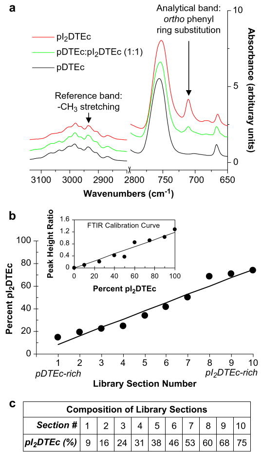
Composition of the combinatorial polymer scaffold libraries was characterized using FTIR (NEXUS 670 FTIR spectrophotometer, Nicolet, Thermo Electron, Madison, WI). A library was cut into 10 sections of length 7.5 mm and dissolved in chloroform. Measurements were conducted by casting the polymer solutions onto a KBr pellet and recording spectra at a resolution of 4cm−1, 64 scans and total range 4000–650 cm−1. Analysis was performed with OMNIC (Version 7.2, Thermo Electron). Baseline deduction and normalization to maximum absorbance were performed on all spectra. A calibration curve was established using FTIR spectra of nine blends of known pDTEc/pI2DTEc composition (Fig. 2b inset). Absorbance at 2935 cm−1 was chosen as the reference band (methyl stretching) while absorbance at 710 cm−1 was chosen as the analytical band (ortho-phenyl ring substitution, iodine) [18,20]. Peak height ratios of sections (710 cm−1/2935 cm−1) from the combinatorial scaffold libraries were determined and corresponding compositions were calculated using the calibration curve [21]. Peak height was calculated from baseline.
Fig. 2.
(a) Control FTIR spectra of pDTEc, pI2DTEc and pDTEc: pI2DTEc (1:1). Reference band was 2935 cm−1 while 710 cm−1 was the analytical band. (b) The composition of sections from a pDTEc/pI2DTEc scaffold library was determined from peak height ratios (710 cm−1/2935 cm−1) using a calibration curve (inset). Lines were fit by linear regression and the Pearson correlation coefficients for the calibration curve (inset) and scaffold libraries (main plot) were 0.97 (P < 0.0001) and 0.98 (P < 0.0001), respectively. (c) The composition for each library section was calculated from the linear fit to data plotted in Panel (b).
2.3. Scanning electron microscopy
Scaffolds were frozen in liquid nitrogen and sectioned with a razor to expose interior. After sputter-coating with gold, pores were viewed by SEM (15 kV, Hitachi S-4700-II FE-SEM, Pleasanton, CA). ImageJ (1.37v, Wayne Rasband, National Institutes of Health, USA) was used to measure diameter of six randomly chosen pores in SEM images at the compositions indicated.
2.4. X-ray microradiography and dental radiography
Scaffold libraries plus controls were imaged in an X-ray microradiometer (80 kVp, 3 mA, 180 s exposure, closest possible distance setting, HP Cabinet X-ray System, Faxitron Series, McMinnville, OR) using X-ray film (VRP-M green sensitive film, UAB Geola, Vilnius, Lithuania) and with a dental X-ray instrument (70 kVp, 7 mA, 0.13 s exposure (eight pulses), 75 mm distance, Gendex GX-770, Lake Zurich, IL) using 75 mm occlusal film (DF-50 single, Ultraspeed, Kodak, Rochester, NY). Developed X-ray films were digitally imaged (VersaDoc, Bio-Rad, Hercules, CA) for presentation in figures and for densitometry analysis using Quantity One software (Bio-Rad). Ten evenly spaced regions 7.5 mm in length running lengthwise along each gradient library were selected for densitometry. Background regions were subtracted from libraries and controls. Note that OD values for samples with high X-ray contrast, such as control pI2DTEc scaffolds, become negative after background subtraction. This is because radiographs are “negatives” and objects with high X-ray contrast appear light and have low pixel intensity values while background areas are dark and have high pixel intensity values.
2.5. X-ray microcomputed tomography
The internal morphology of the scaffolds was characterized by μCT (μCT 40, Scanco Medical, Bassersdorf, Switzerland). The microfocus X-ray source was set at 45 kVp and 177 μA to give a spot size of 5 mm. The samples were scanned at an 8-μm voxel resolution with an integration time of 0.3 s. The libraries were scanned whole and then analyzed in sections using manufacturer's imaging, evaluation solution and analysis software. Porosity, pore size and wall thickness were calculated by direct distance transformation methods [22,23]. Note that additional descriptors of scaffold structure have been calculated from μCT images (accessible void volume [24], throat size [25], modal interconnect length [26]) but were not determined here since they were not required for evaluating radiopacity of the scaffolds. For 3D reconstructions, sigma of 1 and support of 1.2 were used. Threshold values were varied for reconstructions as indicated in results and figures. For histograms of voxel intensity versus frequency of occurrence, voxel intensities provided by the instrument were divided by 32.767 to put them on the same scale as threshold values (−1000 to 1000). Note that negative voxel intensity values represent instrument noise and are not physically meaningful.
2.6. Disclaimers
The content is solely the responsibility of the authors and does not necessarily represent the official views of the NIH, NIBIB, NCMHD or NIST. This article, a contribution of the National Institute of Standards and Technology, is not subject to US copyright. Certain equipment and instruments or materials are identified in the paper to adequately specify the experimental details. Such identification does not imply recommendation by NIST, nor does it imply the materials are necessarily the best available for the purpose.
3. Results and discussion
3.1. Library characterization by Fourier transform infrared spectroscopy
pDTEc/pI2DTEc combinatorial scaffold libraries were fabricated (Fig. 1) to determine the minimum amount of pI2DTEc contrast agent necessary for various X-ray-based imaging techniques. The composition of the libraries was verified by FTIR (Fig. 2) using a calibration curve made from FTIR measurements of pDTEc/pI2DTEc blends of known composition (Fig. 2b inset). The results demonstrate that the composition of the libraries changes linearly from 9% to 75% pI2DTEc (by mass) along their length (R = 0.98, P < 0.0001) (Fig. 2b,c) in agreement with previous measurements [19].
3.2. Library characterization by scanning electron microscopy
Large, open pores were observed in the scaffold libraries with pore size range 200–400 μm, suitable for bone tissue engineering (Fig. 3a,c,e) [27,28]. Smaller voids (<10 μm) were also found in the scaffold walls (Fig. 2b,d,f), which were attributed to the dioxane sublimation during freeze-drying. The large and small pore morphologies were similar for all scaffold compositions in the libraries as well as for pure pDTEc and pI2DTEc control scaffolds. SEM micrographs were analyzed with ImageJ to determine pore size. No significant difference in pore size (P < 0.05) was detected for the five compositions tested as determined by ANOVA with Tukey's test for multiple comparisons: 314 (35) μm, 292 (68) μm, 300 (39) μm, 323 (56) μm and 293 (66) μm for pDTEc control, section 2, section 5, section 9 and pI2DTEc control, respectively (S.D. in parentheses; n = 6). These results indicate that scaffold morphology was not affected by pDTEc/pI2DTEc composition and suggest that any corresponding differences in X-ray imaging can be attributed to variations in scaffold composition (not scaffold architecture). In addition, undissolved NaCl crystals were not found in the scaffolds indicating that all the NaCl had been leached and that the scaffold pores were interconnected.
Fig. 3.
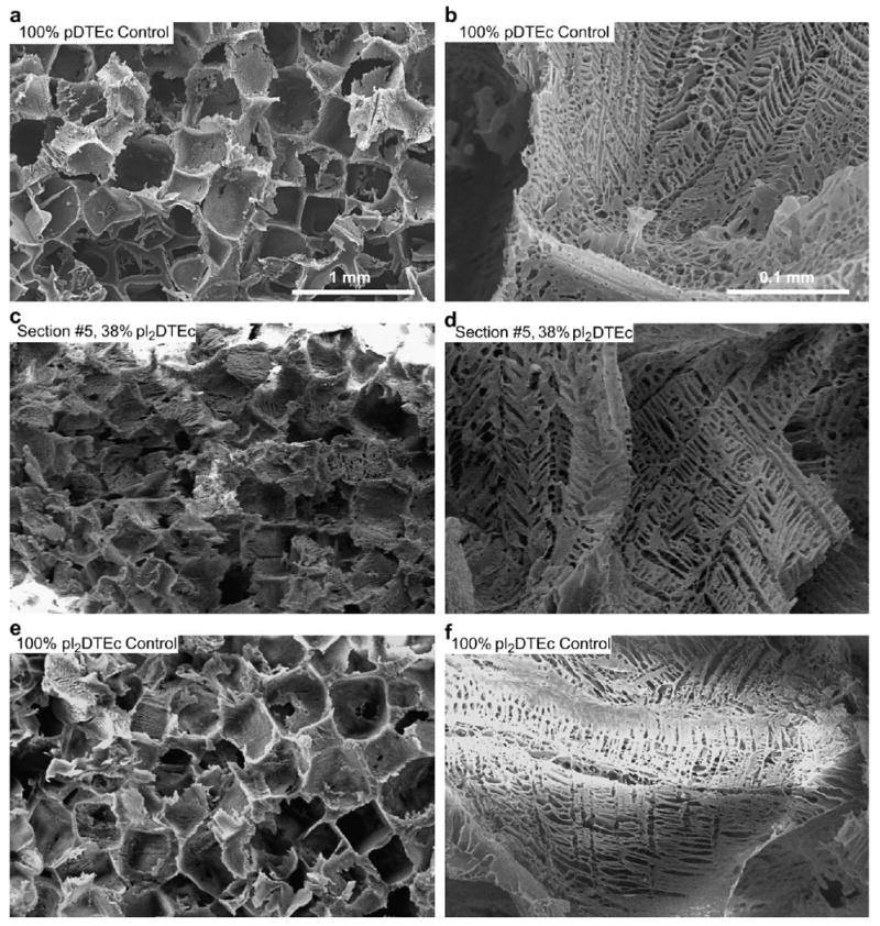
Combinatorial pDTEc/pI2DTEc scaffold libraries and controls were examined by SEM and representative images are shown. (a,b) Control pure pDTEc scaffold. (c,d) Library section #5 (38% pI2DTEc by mass). (e,f) Control pure pI2DTEc scaffold. Size bar in (a) applies to (c) and (e). Size bar in (b) applies to (d) and (f).
3.3. Porosity and gravimetrics
Scaffold porosity can be calculated gravimetrically from polymer density (pDTEc = 1.1 g/mL; pI2DTEc = 1.5 g/mL), scaffold mass, scaffold volume, NaCl mass and NaCl density (2.2 g/mL) as described previously [19]. Scaffold total porosity was ≈98% where macropores from NaCl-leaching caused ≈83% porosity and microvoids in the scaffold wall from dioxane sublimation caused ≈15% porosity.
3.4. Imaging libraries by X-ray microradiography
Scaffold libraries were imaged by X-ray microradiography to determine the amount of pI2DTEc required for sufficient contrast. Note that polymer specimen thickness will also affect radiopacity, though this was not the focus of the present study. As judged by visual assessment, a gradient in X-ray contrast was visible in microradiographs of the scaffold libraries (Fig. 4a) which mirrored the gradient in pI2DTEc composition. Qualitatively, the control pI2DTEc scaffold also gave high X-ray contrast while control pDTEc was barely visible by microradiography (Fig. 4a). For quantitative assessment, densitometry analysis demonstrated a linear change in optical density (OD) along the pDTEc/pI2DTEc scaffold library (R = 0.99; P < 0.0001) (Fig. 4b). These results show that 9% pI2DTEc (by mass), which was the amount of pI2DTEc present in section 1 of the scaffold libraries, was sufficient to make the scaffolds visible by X-ray microradiography (Table 1).
Fig. 4.
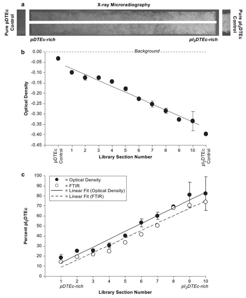
(a) X-ray microradiographs of a gradient scaffold library (75 mm long) plus controls are shown. The white line down the middle of the gradient is from the steel wire. (b) Optical density (OD) was determined for 10 sections (7.5 mm) along microradiographs. Libraries were averaged and error bars are standard deviation (n = 2). OD values for controls are shown on ends of plot. Linear regression line has a Pearson correlation coefficient of 0.99 (P < 0.0001). (c) Data from Panel (b) was used to calculate library composition (solid circles) using the OD values of control scaffolds (pDTEc and pI2DTEc) for calibration. For comparison, library composition determined by FTIR (Fig. 2b) is shown (open circles). Linear regression lines had the Pearson correlation coefficients of 0.99 (P < 0.0001) and 0.98 (P < 0.0001) for OD (solid line) and FTIR (dashed line), respectively.
Table 1.
Minimum fraction pI2DTEc required for effective imaging of pDTEc scaffolds by X-ray techniques
| X-ray technique | Library section no. | pI2DTEc (% by mass) | Iodine atoms per gram of scaffold (mmol) |
|---|---|---|---|
| Microradiography | 1 | 9 | 0.28 |
| Dental radiography | 2 | 16 | 0.50 |
| Dental radiography through muscle tissue | 5 | 38 | 1.20 |
| Microcomputed tomography | 6 | 46 | 1.45 |
3.5. Imaging libraries by dental radiography
The combinatorial pDTEc/pI2DTEc scaffold libraries were imaged with a dental X-ray instrument of the type used to screen for tooth decay during dental appointments. As judged by visual assessment, the scaffold libraries were visible in dental radiographs (Fig. 5a) but were fainter than for the microradiographs (Fig. 4a). The control pI2DTEc scaffold was qualitatively visible (Fig. 5a) but control pDTEc was not perceptible by dental radiography (Fig. 5a). For quantitative assessment, densitometry analysis revealed a linear change in OD along the pDTEc/pI2DTEc scaffold libraries (R = 0.99; P < 0.0001) (Fig. 4b) but it was not until section 2 (16% pI2DTEc by mass) that the library OD value became discernible from background.
Fig. 5.
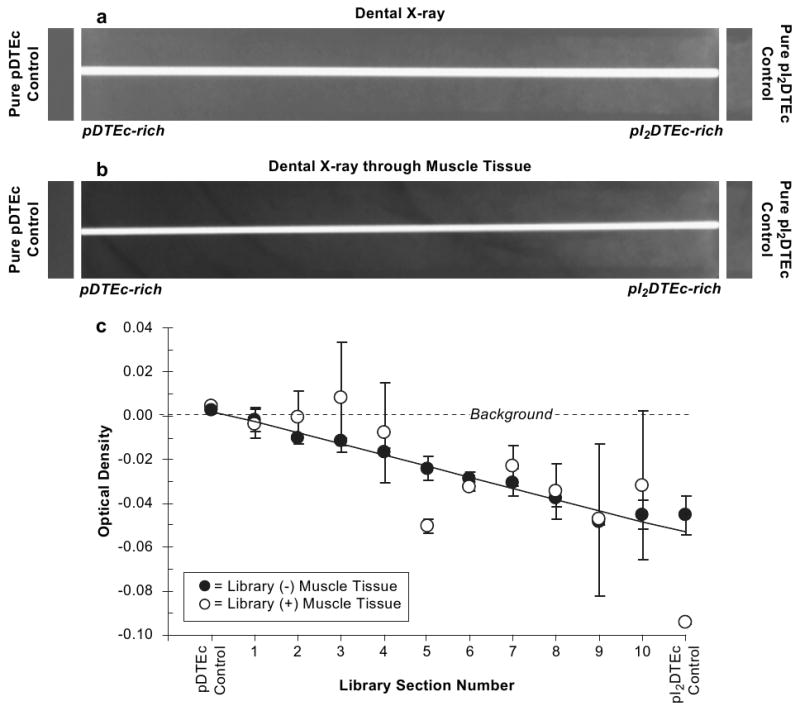
(a) Dental X-ray radiographs of a gradient scaffold library plus controls are shown. The white line down the middle of the radiograph is from the steel wire. (b) Scaffold libraries were covered by tissue (beef round steak, 0.75 cm thickness) and imaged by dental radiography to simulate imaging after implantation (center). (c) Optical density (OD) was determined by densitometry for 10 sections (7.5 mm) along the library radiographs. Both libraries were averaged and error bars are standard deviation of the mean (n = 2). Without and with muscle tissue are closed and open circles, respectively. OD values for control scaffolds are shown on ends of the plot. Linear regression lines had the Pearson correlation coefficients of 0.99 (P < 0.0001) and 0.74 (P < 0.01) without (solid line) and with muscle tissue (dashed line), respectively.
In order to simulate imaging by an oral surgeon following implantation, the pDTEc/pI2DTEc scaffold libraries were imaged by dental radiography through 0.75 cm of muscle tissue (beef round steak) (Fig. 5b). As judged by visual assessment, the presence of tissue further obscured X-ray imaging making the library invisible on the pDTEc-rich end (Fig. 5b). Pure pDTEc was also qualitatively invisible while pure pI2DTEc gave contrast. For quantitative assessment, densitometry showed that OD of the library was not discernible from background until section 5 (38% pI2DTEc by mass). These results reveal that 16% and 38% were the minimum amounts of pI2DTEc (by mass) that must be included in the scaffolds to make them visible by dental radiography in the absence or presence of tissue, respectively (Table 1).
3.6. Imaging libraries by X-ray microcomputed tomography
Fig. 6 illustrates how μCT image quality is affected by scaffold radiopacity. μCT was used to image control pDTEc, pI2DTEc and PDLLA scaffolds and 3D reconstructions at several different threshold values are shown (Fig. 6a). A visual assessment of the grayscale images of control pDTEc and PDLLA scaffolds revealed that these scaffolds had poor X-ray contrast and it was difficult to discern the scaffold from the background. In contrast, the grayscale image of the control pI2DTEc scaffold yielded a sharp image with well-defined pores and struts. For segmented images, the best image quality occurred at different threshold values for pDTEc and pI2DTEc. Despite high noise levels, pores were most evident for pDTEc at threshold 0, whereby, no pore structure could be detected when the threshold was increased to 10. The pDTEc image became blank for thresholds 50 and 109. Similar results were observed for PDLLA scaffolds. On the other hand, pI2DTEc was a solid block at thresholds 0 and 10 while thresholds of 50 and 109 (optimal threshold as determined by adaptive thresholding, see explanation below) produced realistic images of the scaffold morphology. These results qualitatively demonstrate how μCT image quality is affected by material radiopacity.
Fig. 6.
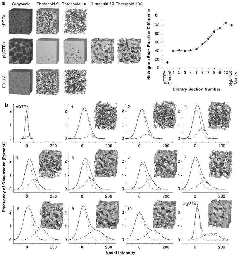
(a) Control scaffolds were imaged by μCT and 3D reconstructions (1.3 × 1.3 × 1.5 mm) at indicated thresholds are shown. For thresholds 50 or 109, segmentation images could not be constructed for pDTEc or PDLLA because voxel intensities were too low. (b) Histograms of “voxel intensity” (grey level) versus “frequency of occurrence” for 10 sections from a scaffold library plus controls using a volume of 2.5 mm (5,277,888 voxels) are shown (solid line). Nonlinear least squares fitting of two Gaussian peaks are represented by the two dashed line peaks under each histogram. All Gaussian fits had the Pearson correlation coefficients greater than 0.99. Insets are 3D reconstructions using threshold 50. (c) The difference between the center positions of the two Gaussian peak fits in Panel (b) was plotted against library section. Line is to aid the reader's eye.
Next, the quality of μCT images of pDTEc/pI2DTEc scaffold library sections was compared directly using the same threshold for image reconstruction [29]. A fixed threshold of 50 was chosen for constructing the images since this value optimized the overall binary pore-solid space for all compositions as judged by visual assessment. As shown in Fig. 6b, the contrast, image quality and pore definition improved as pI2DTEc content increased. Images were noisy from scaffold sections 1 through 5 but began to sharpen at section 6 (46% pI2DTEc by mass). To further evaluate μCT image quality, histograms of “voxel intensity” versus “frequency of occurrence” were examined for each library section along with controls (Fig. 6b). Ideally, image histograms possess two well-resolved peaks where the left peak is representative of noise and the right peak is representative of signal [30]. For scaffold libraries and controls, each histogram showed a large main peak near zero with a shoulder which became more right-shifted (higher voxel value) as the pI2DTEc composition increased. When two Gaussian peaks were fit to the histograms, the left peak position remained stationary while the right peak shifted to the right as pI2DTEc content increased. The difference in the peak positions was plotted against library section (Fig. 6c). An inflection point became apparent at library section 5 indicating that signal began to resolve from noise for library sections 6 (46% pI2DTEc by mass) and above. These results suggest that 46% is the minimum amount of pI2DTEc (by mass) that must be included in a scaffold blend to enable effective imaging by μCT (Table 1). These results also demonstrate how combinatorial scaffold libraries can deliver a wealth of valuable data for evaluating the effect of radiocontrast agent concentration on the quality of μCT imaging.
3.7. Calculating scaffold structural parameters from X-ray microcomputed tomography
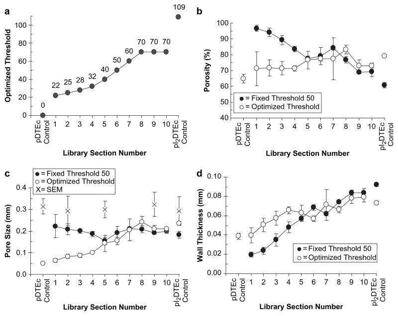
The main goal of the current study was to evaluate the effect of radiocontrast agent concentration on X-ray-based imaging of scaffolds and this objective has been addressed above. However, we also examined μCT's ability to quantify structural parameters such as porosity, pore size and wall thickness [22,23]. In Fig. 7, scaffold structural parameters have been determined for the pDTEc/pI2DTEc scaffold library sections plus controls using two different analyses. First, structural parameters were determined for each library section using a constant threshold of 50 [29]. The second approach uses “optimized” thresholds determined by either adaptive thresholding [30] or visual acuity [24,31] (Fig. 7a). The adaptive thresholding algorithm finds the lowest point between two peaks in voxel intensity histograms as the optimal threshold. This approach was only applicable for the pI2DTEc control scaffold and yielded 109 as the optimal threshold. Visual acuity was used to identify “optimized” thresholds for pDTEc/pI2DTEc library sections and control pDTEc since histogram minima were not present for these materials.
Fig. 7.
(a) Optimized thresholds for pDTEc/pI2DTEc library μCT images (plus controls) are plotted (values given above each point). A thresholding algorithm [30] identified an optimal threshold for control pI2DTEc but not for the libraries or control pDTEc. Visual acuity (operator-selected) was used to determine optimized threshold for libraries and control pDTEc [24,31]. (b–d) Scaffold library μCT images were analyzed using a constant threshold of 50 (solid circles) or the optimized thresholds (open circles) as given in Panel (a). Porosity, pore size and wall thickness are given in (b), (c) and (d), respectively. Five cubes of 2.5 mm3 volume (5,277,888 voxels) were analyzed for each section and averaged. Error bars are standard deviation (n = 5). Control pDTEc values at threshold 50 are not shown because a segmentation image could not be obtained. Pore size calculated from ImageJ analysis of electron micrographs is shown in (c) (“X” symbols, n = 6 pores, error bars are S.D.). Lines are to aid the reader's eye. Similar results were obtained for both libraries.
Structural parameters for the scaffold libraries and controls calculated using the fixed threshold approach and the “optimized” threshold approach were compared (Fig. 7). Using a fixed threshold of 50, μCT image analysis showed that calculated porosity decreased and wall thickness increased as the fraction of pI2DTEc increased, while calculated pore size remained relatively constant for the entire library. Using the “optimized” threshold values, the porosity remained relatively constant, while the calculated pore size and wall thickness increased with increasing fraction of pI2DTEc. The fixed threshold 50 plot and optimized threshold plot for porosity overlaid each other from library sections 10 through 5 but diverged from sections 4 through 1. Similar trends were observed for the plots for pore size and wall thickness. The overlap of “fixed” and “optimized” at library section 5 and higher indicated that the values of the calculated structural parameters became less dependent on the chosen threshold as fraction pI2DTEc increased. These results support the earlier conclusion that 46% is the minimum fraction of pI2DTEc (by mass) that must be included in pDTEc scaffolds to enable effective μCT imaging.
Practical questions that arise regarding the μCT-calculated scaffold structural parameters include: (1) are the calculated structural parameters accurate? and (2) does accuracy depend on pI2DTEc content? First, it is important to bear in mind that pDTEc/pI2DTEc composition did not affect the scaffold structural morphology as supported by SEM results (Fig. 3). This means that ideally porosity, pore size and wall thickness should remain constant throughout the pDTEc/pI2DTEc composition range. The control pI2DTEc will be the focus of the discussion of μCT-structural parameter accuracy because this scaffold would be expected to provide the most accurate parameters using its optimized threshold of 109. A porosity of 79% (S.D. = 1%, n = 5) was calculated for the control pI2DTEc scaffold from μCT. As compared to the 83% “macro”-porosity determined from the gravimetric calculation (see Section 3.3 above), there was a small but reasonable difference (4% porosity), consistent with previous observations [24,31]. The plot of “optimized” threshold porosity in Fig. 7b was relatively flat and did not vary by more than 10% porosity from the pI2DTEc control for all pDTEc/pI2DTEc library compositions. These results indicate that the porosity calculated using “optimized” threshold was accurate (agrees with gravimetrics) and did not vary greatly with scaffold pDTEc/pI2DTEc composition.
Finally, accuracy of μCT-calculated pore size is addressed. The pore size calculated for the control pI2DTEc scaffold (threshold 109) was 236 μm (S.D. = 8 μm; n = 5) which was smaller than that determined by SEM (293 μm, S.D. = 66 μm; n = 6) and smaller than the porogen (sieve sizes 250 μm and 425 μm). Previous work has shown that μCT-calculated scaffold pore sizes are typically smaller than the size of the porogen [31]. Pore sizes calculated with “optimized” thresholds were lower than for the pI2DTEc control but gradually increased from library sections 1 through 6. However, pore sizes for section 7 (53% pI2DTEc by mass) and higher agreed with pI2DTEc control, indicating that inclusion of higher amounts of pI2DTEc was necessary for the pDTEc/pI2DTEc blends to yield agreement with the pI2DTEc control. These results suggest that μCT-calculated pore sizes became more accurate as pI2DTEc content increased.
3.8. Potential application to other polymer systems
In the current work, the combinatorial library approach was used to determine the minimum amount of radiocontrast agent required for imaging polymeric scaffolds by various X-ray techniques. The system used to demonstrate the approach involved blending a radiolucent polymer (pDTEc) with an iodinated, radiopaque polymer (pI2DTEc). The combinatorial approach could also be applied to systems where inclusion of heavy atom salts [2,3] or small organic molecules [4] are used to impart radiopacity. The pure polymer would be loaded in one syringe pump (as shown in Fig. 1c) while the polymer mixed with a maximum amount of radiocontrast agent (heavy atom salt or small organic) would be placed in the second syringe pump to create combinatorial scaffold libraries possessing a gradient in composition. Analysis protocols for optimizing composition would then be the same as described herein.
4. Conclusions
Radiopacity is a desirable property for a biomaterial since it enables convenient imaging by a variety of X-ray techniques. However, doping materials with radiocontrast agents can affect properties and performance. Thus, we have used the pDTEc/pI2DTEc system to demonstrate how combinatorial scaffold libraries can be used to identify formulations that possess sufficient contrast for X-ray imaging but minimize the concentration of radiocontrast agent (pI2DTEc). Only two scaffold libraries were required to determine that a minimum of 9%, 16%, 38% or 46% pI2DTEc (by mass) was necessary for effective imaging of scaffolds by microradiography, dental radiography, dental radiography through 0.75 cm of muscle tissue or microcomputed tomography, respectively.
Acknowledgments
We acknowledge helpful contributions from Jirun Sun (NIST). S.M.D. acknowledges support from the NIST-NSF summer undergraduate research fellowship (SURF). This work was supported in part by NIH R21 EB006497-01. Polymers were synthesized at Rutgers University supported by RESBIO (Integrated Technology Resource for Polymeric Materials) funded by National Institutes of Health (NIBIB and NCMHD) under grant P41 EB001046. Standard deviation (S.D.) is the same as the combined standard uncertainty for the purposes of this work.
References
- 1.Mottu F, Rufenacht DA, Doelker E. Radiopaque polymeric materials for medical applications: current aspects of biomaterial research. Invest Radiol. 1999;34:323–35. doi: 10.1097/00004424-199905000-00001. [DOI] [PubMed] [Google Scholar]
- 2.Deb S, Vazquez B. The effect of cross-linking agents on acrylic bone cements containing radiopacifers. Biomaterials. 2001;22:2177–81. doi: 10.1016/s0142-9612(00)00409-9. [DOI] [PubMed] [Google Scholar]
- 3.Nuutinen JP, Clerc C, Tormala P. Mechanical properties and in vitro degradation of self-reinforced radiopaque bioresorbable polylactide fibers. J Biomater Sci Polym Ed. 2003;14:665–76. doi: 10.1163/156856203322274923. [DOI] [PubMed] [Google Scholar]
- 4.Deb S, Abdulghani S, Behiri JC. Radiopacity in bone cements using an organo-bismuth compound. Biomaterials. 2002;23:3387–93. doi: 10.1016/s0142-9612(02)00039-x. [DOI] [PubMed] [Google Scholar]
- 5.Jay MJ, Ryo UY. Biodegradable low biological toxicity radiographic contrast medium and method of X-ray imaging. US Patent No 5019370. 1991
- 6.Kohn JB, Bolikal D, Pendharkar SM. Radio-opaque polymer biomaterials. US Patent No 7056493. 2006
- 7.Weber N, Pesnell A, Bolikal D, Zeltinger J, Kohn J. Viscoelastic properties of fibrinogen adsorbed to the surface of biomaterials used in blood-contacting medical devices. Langmuir. 2007;23:3298–304. doi: 10.1021/la060500r. [DOI] [PubMed] [Google Scholar]
- 8.Maier WF, Kirsten G, Orschel M, Wei PA, Holzwarth A, Klein J. Combinatorial chemistry of materials, polymers, and catalysts. In: Malhotra R, editor. Combinatorial materials development. Washington, DC: American Chemical Society; 2002. pp. 1–3. [Google Scholar]
- 9.Dooley CT, Chung NN, Wilkes BC, Schiller PW, Bidlack JM, Pasternak GW, et al. An all D-amino acid opioid peptide with central analgesic activity from a combinatorial library. Science. 1994;266:2019–22. doi: 10.1126/science.7801131. [DOI] [PubMed] [Google Scholar]
- 10.Rohrer SP, Birzini ET, Mosley RT, Berk SC, Hutchins SM, Shen DM, et al. Rapid identification of subtype-selective agonists of the somatostatin receptor through combinatorial chemistry. Science. 1998;282:737–40. doi: 10.1126/science.282.5389.737. [DOI] [PubMed] [Google Scholar]
- 11.Brocchini S, James K, Tangpasuthadol V, Kohn J. Structure-property correlations in a combinatorial library of degradable biomaterials. J Biomed Mater Res. 1998;42:66–75. doi: 10.1002/(sici)1097-4636(199810)42:1<66::aid-jbm9>3.0.co;2-m. [DOI] [PubMed] [Google Scholar]
- 12.Meredith JC, Sormana JL, Keselowsky BG, Garcia AJ, Tona A, Karim A, et al. Combinatorial characterization of cell interactions with polymer surfaces. J Biomed Mater Res. 2003;66A:483–90. doi: 10.1002/jbm.a.10004. [DOI] [PubMed] [Google Scholar]
- 13.Anderson DG, Putnam D, Lavik EB, Mahmood TA, Langer R. Biomaterial microarrays: rapid microscale screening of polymer–cell interaction. Biomaterials. 2005;26:4892–7. doi: 10.1016/j.biomaterials.2004.11.052. [DOI] [PubMed] [Google Scholar]
- 14.Simon CG, Jr, Eidelman N, Deng Y, Kennedy SB, Sehgal A, Khatri CA, et al. Combinatorial screening of cell proliferation on poly(l-lactic acid)/poly(d,l-lactic acid) blends. Biomaterials. 2005;26:6906–15. doi: 10.1016/j.biomaterials.2005.04.050. [DOI] [PubMed] [Google Scholar]
- 15.Yang Y, Bolikal D, Becker ML, Kohn J, Simon CG., Jr Combinatorial polymer scaffold libraries for screening cell–biomaterial interactions in 3D. Adv Mater. submitted for publication. [Google Scholar]
- 16.Langer R, Vacanti JP. Tissue engineering. Science. 1993;260:920–6. doi: 10.1126/science.8493529. [DOI] [PubMed] [Google Scholar]
- 17.Vacanti JP, Morse MA, Saltzman WM, Domb AJ, Perez-Atayde A, Langer R. Selective transplantation using bioresorbable artificial polymers as matrices. J Pediatr Surg. 1988;23:3–9. doi: 10.1016/s0022-3468(88)80529-3. [DOI] [PubMed] [Google Scholar]
- 18.Ertel SI, Kohn J. Evaluation of a series of tyrosine-derived polycarbonates as degradable biomaterials. J Biomed Mater Res. 1994;28:919–30. doi: 10.1002/jbm.820280811. [DOI] [PubMed] [Google Scholar]
- 19.Simon CG, Jr, Stephens JS, Dorsey SM, Becker ML. Fabrication of combinatorial polymer scaffold libraries. Rev Sci Instrum. 2007;78:072207-1–072207-7. doi: 10.1063/1.2755761. [DOI] [PubMed] [Google Scholar]
- 20.Sampathkumar R, Sabesan R, Krishnan S. Infrared characterization of 2,6-diaryl-4-piperidones. J Mol Liquid. 2006;126:130–4. [Google Scholar]
- 21.Eidelman N, Simon CG., Jr Characterization of combinatorial polymer blend composition gradients by FTIR microspectroscopy. J Res Natl Inst Stand Technol. 2004;109:219–31. doi: 10.6028/jres.109.014. [DOI] [PMC free article] [PubMed] [Google Scholar]
- 22.Hildebrand T, Ruegsegger P. A new method for the model-independent assessment of thickness in three-dimensional images. J Microsc. 1997;185:67–75. [Google Scholar]
- 23.Hildebrand T, Laib A, Muller R, Dequeker J, Ruegsegger P. Direct three-dimensional morphometric analysis of human cancellous bone: microstructural data from spine, femur, iliac crest, and calcaneus. J Bone Miner Res. 1999;14:1167–74. doi: 10.1359/jbmr.1999.14.7.1167. [DOI] [PubMed] [Google Scholar]
- 24.Moore MJ, Jabbari E, Ritman EL, Lu L, Currier BL, Windebank AJ, et al. Quantitative analysis of interconnectivity of porous biodegradable scaffolds with micro-computed tomography. J Biomed Mater Res A. 2004;71A:258–67. doi: 10.1002/jbm.a.30138. [DOI] [PubMed] [Google Scholar]
- 25.Otsuki B, Takemoto M, Fujibayashi S, Neo M, Kokubo T, Nakamura T. Pore throat size and connectivity determine bone and tissue ingrowth into porous implants: three-dimensional micro-CT based structural analyses of porous bioactive titanium implants. Biomaterials. 2006;27:5892–900. doi: 10.1016/j.biomaterials.2006.08.013. [DOI] [PubMed] [Google Scholar]
- 26.Jones JR, Poologasundarampillai G, Atwood RC, Bernard D, Lee PD. Non-destructive quantitative 3D analysis for the optimisation of tissue scaffolds. Biomaterials. 2007;28:1404–13. doi: 10.1016/j.biomaterials.2006.11.014. [DOI] [PubMed] [Google Scholar]
- 27.Klawitter JJ, Hulbert SF. Application of porous ceramics for the attachment of load bearing internal orthopedic applications. J Biomed Mater Res. 1971;2:161–229. [Google Scholar]
- 28.Tsuruga E, Takita H, Itoh H, Wakisaka Y, Kuboki Y. Pore size of porous hydroxyapatite as the cell-substratum controls BMP-induced osteogenesis. J Biochem. 1997;121:317–24. doi: 10.1093/oxfordjournals.jbchem.a021589. [DOI] [PubMed] [Google Scholar]
- 29.Lin AS, Barrows TH, Cartmell SH, Guldberg RE. Microarchitectural and mechanical characterization of oriented porous polymer scaffolds. Biomaterials. 2003;24:481–9. doi: 10.1016/s0142-9612(02)00361-7. [DOI] [PubMed] [Google Scholar]
- 30.Ridler TW, Calvard S. Picture thresholding using an iterative selection method. IEEE Trans Syst Man Cybern. 1978;8:630–2. [Google Scholar]
- 31.Lin-Gibson S, Cooper JA, Landis FA, Cicerone MT. Systematic investigation of porogen size and content on scaffold morphometric parameters and properties. Biomacromolecules. 2007;8:1511–8. doi: 10.1021/bm061139q. [DOI] [PubMed] [Google Scholar]


