Abstract
In scanned-beam proton therapy, the beam spot properties, such as the lateral and longitudinal size and the minimum achievable range, are influenced by beam optics, scattering media and drift spaces in the treatment unit. Currently available spot scanning systems offer few options for adjusting these properties. We investigated a method for adjusting the lateral and longitudinal spot size that utilizes downstream plastic pre-absorbers located near a water phantom. The spot size adjustment was characterized using Monte Carlo simulations of a modified commercial scanned-beam treatment head. Our results revealed that the pre-absorbers can be used to reduce the lateral full width at half maximum (FWHM) of dose spots in water by up to 14 mm, and to increase the longitudinal extent from about 1 mm to 5 mm at residual ranges of 4 cm and less. A large factor in manipulating the lateral spot sizes is the drift space between the pre-absorber and the water phantom. Increasing the drift space from 0 cm to 15 cm leads to an increase in the lateral FWHM from 2.15 cm to 2.87 cm, at a water-equivalent depth of 1 cm. These findings suggest that this spot adjustment method may improve the quality of spot-scanned proton treatments.
1. Introduction
From May 2008 to December 2009, The University of Texas M D Anderson Cancer Center treated approximately 200 patients with prostate cancer using a magnetically scanned proton beam, applying the so-called discrete spot scanning method, in which the dose is delivered to small `pencil' spots inside the target volume by use of quasi-monoenergetic Bragg peaks (Pedroni et al 2005, Chu 2006). By adjusting the magnetic field gradient during beam off times, the location of the beam's centroid is steered in a lateral direction, while the penetration range is adjusted by changing the energy at which protons are extracted from the synchrotron. Thus, a three-dimensional target volume can be painted by superpositioning a large number of single dose spots. The two basic parameters of scanned proton beam dosimetry are the range of a single pencil beam in water, which is determined by the kinetic energy of the protons, and the shape of the dose spot. The latter is characterized as both the lateral spot size (perpendicular to the beam direction) at the depth of maximum dose (dmax) and the longitudinal spot size (along the beam direction) between the proximal and the distal 80% dose location (as well as the proximal and distal 90% dose locations), all of which vary with the beam's energy. These parameters are the basic building blocks of any desired dose distribution, and they determine the slope of the dose falloff in the penumbral regions. Bues et al (2005) determined that the penumbra of a proton dose distribution delivered by scanned pencil beams relates to the full width at half maximum (FWHM) of a single beam spot in the absence of additional beam collimating devices, such that the 80% to 20% penumbra is approximately 0.55 times the FWHM of the spot in water. Safai et al. (2008) compared the lateral penumbrae of collimated double-scattered beams with those of uncollimated scanned beam in a theoretical study, and they concluded that scanned beams produce larger penumbrae in shallow treatments, such as head and neck cancer sites, because of the relatively large size of the spots. They also pointed out in their study that smaller spot sizes could significantly reduce the penumbra. However, there are limits of the achievable spot size, based on the design and instrumentation implemented into a clinical scanning beam treatment head.
Before entering a treatment head, the proton beams penetrate a vacuum window, and depending on the window material and its thickness, substantial scatter can be introduced into the beam. Downstream of the vacuum window there is usually a large drift space (2–3 m) where the beam threads through the steering magnets and the treatment head that contains ionization chambers, beam-profile monitors and beam-position monitors, each of which adds scatter to the proton beam. Various techniques have been reported to minimize spot size, including using beam optics, minimizing the material in the beam path, and He-filled chambers to reduce scatter in drift spaces (Pedroni et al 1995, 2004, Kanai et al 2006, 1980, Pedroni and Enge 1995, Coutrakon et al 2003).
The proton scanning beam technique has been used by the following six treatment facilities: (1) the Gesellschaft für Schwerionenforschung (GSI) in Darmstadt, Germany (Haberer et al 1993); (2) the Paul Scherrer Institute (PSI) in Villigen, Switzerland (Pedroni et al 1995); (3) the Rinecker Proton Therapy Center (RPTC) in Munich, Germany; (4) the Francis H Burr Proton Therapy Center at the Massachusetts General Hospital (MGH) in Boston, MA, USA; (5) the Heidelberger Ionenstrahl-Therapiezentrum (HIT) in Heidelberg, Germany; and (6) and the Proton Therapy Center at M D Anderson Cancer Center in Houston, TX, USA. Recent investigations (Sawakuchi et al 2008, 2010) of the treatment apparatus at our institution revealed that the lateral extent of the spots as a function of the beam's energy has a peculiar shape because of the competing effects of multiple Coulomb scattering (MCS) in the treatment head and in the patient or in the phantom and nuclear reactions. In general, the lateral spot size is large at the lowest and highest initial proton beam energies (3.7 cm FWHM at 72 MeV or 4 cm range; 2.2 cm FWHM at 221.8 MeV or 30.6 cm range), with a broad minimum at intermediate energies (2.04 cm FWHM near 178.6 MeV, or 21.0 cm range). This behavior may be conceptually understood by the following considerations.
Beam line equipment, such as an upstream beam profile monitor, chamber windows, etc, causes MCS and nuclear reactions. At low initial beam energies, MCS scattering predominates the lateral spot size in the patient. At high beam energies, nuclear interactions in the beam line equipment and MCS in the patient dominate the spot size in the patient (Sawakuchi et al 2008). Consequently, the penumbral sharpness of low-energy beams, e.g., for tumors of the head and neck, could theoretically be increased by reducing the amount of MCS in the beam line equipment. Another aspect of the spot shape is the longitudinal extent. At low energies, the proton beams exhibit less range straggling, and hence the Bragg peaks are relatively narrow, which means that more beam energies are needed to cover a given target volume at shallow depths, when compared with high-energy beams for deeper target volumes of similar sizes. The proton accelerator at our institution is a synchrotron, which provides beam energy changes between beam spills. It takes several seconds to change the energy of the treatment beams; hence the delivery efficiency is directly dependent on the number of energy layers to be delivered. To increase the delivery efficiency, i.e. to reduce the number of energy layers required, in theory, the pencil beam spots may be longitudinally broadened by increasing the amount of range straggling. The range straggling can be increased by increasing the initial beam range (energy) and adding a pre-absorber to degrade the range by an equal amount. Other methods to increase the delivery efficiency were reported, such as the use of ridge filters (Akagi et al 2003, Kostjuchenko et al 2001) and other filters (Li et al 2007), and downstream absorbers were used successfully to minimize the penumbral width in passively scattered proton beams for radiosurgery (Newhauser et al 2002). However, we were unable to find any report on the application of downstream pre-absorbers to substantially improve the lateral properties of scanned proton treatment beams.
The aim of this study was to evaluate the efficacy of adding a downstream pre-absorber in a scanning proton beam to reduce the lateral beam spot size, and thereby extend the interval of the clinically useful beam range to shallower depths. We used Monte Carlo simulations to predict changes in the lateral FWHM and the longitudinal extent of the Bragg peak when downstream pre-absorbers were introduced into the beam path.
2. Materials and methods
A Monte Carlo model of the scanning beam treatment head was validated against measurements of lateral and longitudinal dose profiles in air and in water (Sawakuchi et al 2010). The code MCNPX (Waters et al 2005) version 2.7a was used for all simulations. The MCNPX code was previously validated under a variety of clinically relevant proton therapy conditions (Newhauser et al 2007, 2005, Titt et al 2008). These validation studies revealed adequate dosimetric accuracy, with the exception of Herault et al. (2007), who reported an overprediction of the MCS using the MCNPX code to simulate a proton therapy beam line. Because of the sensitivity of the pencil beam dose distributions to MCS and the potential inadequacy of the implemented MCS model in the standard version of MCNPX, it was necessary to modify the code. An improved scattering routine, very closely approximating the scattering behavior described by the Moliere theory, was introduced into the code. The routine was first suggested by Kuhn and Dodge (1992), was implemented into MCNPX by Stankovskiy et al (2009), and was adapted by us for this study. Apart from MCS, the default models and parameters from the MCNPX code were used.
The geometric model included a detailed representation of the scanning beam treatment head and a water phantom. The water phantom was situated with the upstream surface located at the isocenter location, approximately 323 cm downstream of the proton source location, at the exit window of the evacuated beam transport pipe. Figure 1 shows the schematic setup of the treatment head.
Figure 1.

Schematic diagram of the Monte Carlo model of the scanning beam treatment head and water phantom. Particles emerging from the source (SRC) located at the entrance of the treatment head travel along the z-axis through a beam profile monitor (BPM), followed by a helium chamber (He) which leads through bending magnets (x-Mag and y-Mag). The proton beam traverses a set of two dose monitor ionization chambers (M1 and M2), a spot position monitor chamber (SPM), a pre-absorber (PA), and finally enters the water phantom (H2O) where the beam stops.
Pre-absorbers of various thicknesses, consisting of polymethyl methacrylate (PMMA, C5O2H8, ρ = 1.19 g cm−3), were introduced such that the downstream surface was located at a distance of 5 cm from the upstream surface of the water phantom. The relative water-equivalent ratio (WER) of PMMA (Zhang and Newhauser 2009) was determined by evaluating the residual range of beams in water with a known range through various thicknesses of PMMA slabs, and we used an average relative value of WER=1.16 throughout the study. The residual range, rres, is defined by the depths of the 90% dose location in the water phantom.
In all simulations, a three-dimensional rectangular mesh tally was located in the water phantom, covering the volume from −10 to +10 cm in the x and y directions (lateral to the beam direction) and from 0 to −35 cm in the z direction (beam direction). The mesh voxels were 1 mm3 cubes, and the total deposited energy per unit volume and per source particle history was scored. Because the target was water, with an assigned density of 1 g cm−3, these values are proportional to absorbed dose to water.
Each simulation was performed with 106 source particles, which resulted in statistical uncertainties of less than 1% (1σ confidence interval) in the peak region of the absorbed dose distributions. The systematic uncertainties associated with the resolution of the mesh tally grid were estimated at ±0.25 mm. The simulations were performed on a cluster of 64-bit CPUs running the Linux operating system. Typical simulation times (CPU times) were between about 5 and 8 days.
The first set of simulations modeled the original treatment head, i.e. without the pre-absorber system. This case enabled us to determine the baseline performance of the beamline, i.e. to evaluate the behavior of the lateral FWHM and the longitudinal spot sizes of the Bragg peak of each pencil beam as a function of range, r90, the location of the 90% dose, in water. Ranges in water from r90 = 4 cm up to the maximum available range of r90 = 30.6 cm were simulated in intervals of 1 cm. The second set of simulations characterized the pre-absorber proposed in this study. In this set, the proton beam had a fixed energy, corresponding to a range of 21 cm in water, which corresponds closely to the range exhibiting the minimum lateral FWHM at the peak position, dmax. The residual range, rres, of the beam in the phantom was then modulated by changing the water-equivalent thickness of the pre-absorber, from 1 cm to 20 cm. The third set of simulations was performed with variable initial beam energy and pre-absorbers of thicknesses 5, 10, 15 and 20 cm, located in the beam line. The energy of the proton beam was varied, starting from the water-equivalent thickness of the pre-absorber plus 1 cm, and then increasing in 1 cm increments up to the maximum range in water. For sets 1, 2 and 3, the air gap between the pre-absorber and the water phantom was held constant at 5 cm. In a fourth set of simulations (for the case of a 15 cm thick pre-absorber) the location of the pre-absorber system was varied, with air gaps between the pre-absorber and the phantom of 5, 10 and 15 cm. The fourth set considered four proton beam energies: 159.5, 173.7, 193.0 and 221.8 MeV, corresponding to ranges in water of 17.2, 20.0, 24.05 and 30.6 cm, respectively.
From the three-dimensional absorbed-dose distributions, the longitudinal spot sizes between the 80%–80% and the 90%–90% locations on the central axis and the lateral dose distributions (FWHM) at dmax were evaluated.
3. Results
Figure 2 plots the values of the lateral FWHM of the proton beam spots as a function of the residual range, rres, with pre-absorbers of variable thicknesses and without any pre-absorbers in the beam line. A minimum was observed at 2.02 cm FWHM without a pre-absorber, which established the baseline for the lateral spot size adjustment. Using the pre-absorber system, the lateral FWHM values were smaller for residual ranges below 17 cm. Using an initial proton beam energy of 178.6 MeV, corresponding to a range in water of 21 cm, the FWHM of the spots was less than 2.2 cm in all cases except at a residual range of 1 cm, where the FWHM was 2.23 cm.
Figure 2.
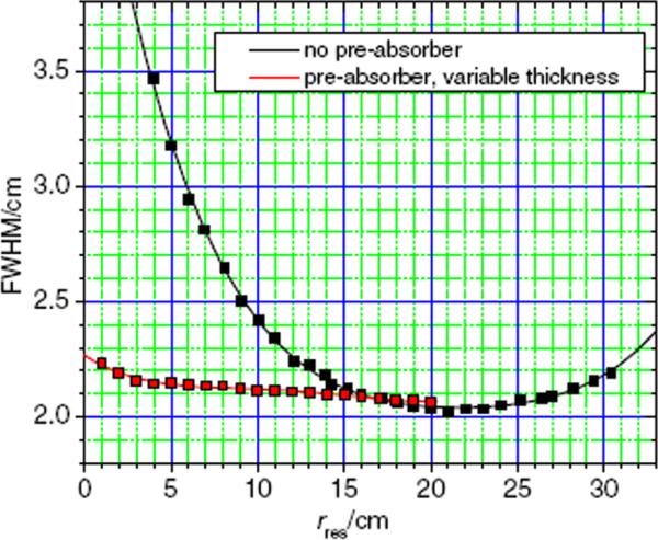
Lateral spot sizes at dmax versus residual range in water without pre-absorbers (black) and with a fixed energy of 178.6 MeV at the treatment head entrance (corresponding to a range of 21 cm in water) and penetrating pre-absorbers of various thicknesses (red).
The longitudinal spot sizes with and without the pre-absorber are shown in figure 3. The data reveal a linear relationship between the longitudinal spot size and the residual range in water. The 80% to 80% longitudinal spot sizes (without pre-absorber) varied from a maximum of about 0.8 cm for the beam with a water-equivalent range of 30.6 cm to about 0.12 cm for a range of 4 cm. The 90% to 90% longitudinal spot sizes varied from a maximum of about 0.5 cm to 0.06 cm.
Figure 3.
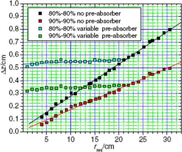
Longitudinal spot sizes between the proximal 80% and distal 80% dose location (black) as well as the proximal 90% and the distal 90% dose location (red) without a pre-absorber and as a function of the residual range in water. Longitudinal spot sizes with a pre-absorber in the beam line are also shown (blue: 80%–80% and green: 90%–90%). The data with the pre-absorber were simulated with a fixed proton beam energy corresponding to a range of 21 cm in water and with variable pre-absorber thicknesses.
When using a fixed initial proton beam range of 21 cm in water and applying pre-absorbers with various thicknesses, the values of the longitudinal spot sizes varied only slightly, with values between 0.51 cm and 0.56 cm (80%–80%) and between 0.32 cm and 0.36 cm (90%–90%), respectively. This behavior is expected because the beam penetrates the same amount of material in each simulation; hence the amount of range straggling is the same.
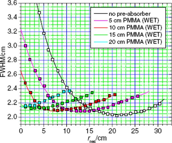
Figure 4 plots the FWHM values of the lateral spot sizes for beams with varying initial energies (i.e. ranges) through pre-absorbers with PMMA thicknesses that correspond to water-equivalent thicknesses of 0, 5, 10, 15 and 20 cm. The lateral spot sizes, after passing through the pre-absorbers, behave similar to those from beams without pre-absorbers, but with a shift toward shallow depths and with slightly larger minima. The lateral spot size minima of 0.208, 0.209, 0.212 and 0.215 cm occurred at residual ranges of about 14, 8, 3 and 1 cm in water for the 5, 10, 15 and 20 cm thick pre-absorbers, respectively.
Figure 4.
Lateral spot sizes as a function of the residual range in water, without a pre-absorber (black) and with a 5 cm (magenta), a 10 cm (red), a 15 cm (green) and a 20 cm (cyan) thick pre-absorber, with a 5 cm air gap between the pre-absorber and the water phantom.
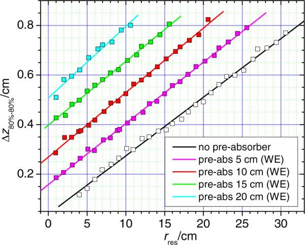
Figure 5 shows the longitudinal spot size (80%–80%) versus residual range for spots in the water phantom that passed through fixed thickness pre-absorbers corresponding to water-equivalent thicknesses of 0, 5, 10, 15 and 20 cm. The data obtained with a pre-absorber behave essentially the same as those obtained without a pre-absorber: there was a linear relationship between the longitudinal spot size and residual range in all cases.
Figure 5.
Longitudinal spot sizes without (black line) a pre-absorber and those with a pre-absorber of fixed thicknesses 5, 10, 15 and 20 cm as a function of the residual range. Only the 80%–80% longitudinal spot sizes are plotted. The 90%–90% longitudinal spot sizes (not shown) exhibited similar behavior but with smaller slopes.
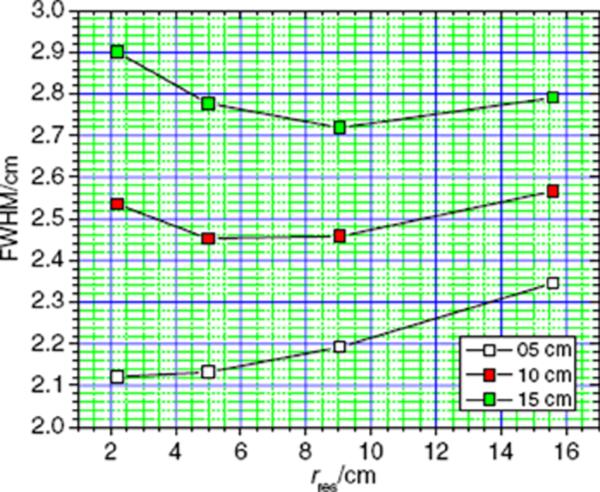
Finally, to evaluate the influence of the size of the air gap on the lateral spot size, the air gap between the downstream surface of the pre-absorber with 15 cm water-equivalent thickness and the upstream surface of the water phantom was varied from 5 cm to 10 cm and to 15 cm. The lateral FWHM of the spots at dmax as a function of the residual range in the water phantom is shown in figure 6. We found that the air gap has a large influence on the lateral spot size. At a shallow depth (2.2 cm) the FWHM increased from 2.12 cm to 2.51 cm and to 2.87 cm, when the air gap was increased from 5 cm to 10 cm and to 15 cm. At a residual range of 5 cm, the lateral size increased from 2.13 cm to 2.41 cm and to 2.74 cm, and at a residual range of 9 cm, the FWHM of the spots varied from 2.19 cm to 2.45 cm and to 2.69 cm. Finally, at a residual range of 15.6 cm, the lateral size of the dose spots increased from 2.34 cm to 2.54 cm and eventually to 2.76 cm.
Figure 6.
Lateral spot size as a function of the residual range in water for three different air gap sizes, 5 cm (white squares), 10 cm (red squares) and 15 cm (green squares), between the downstream surface of the pre-absorber and the upstream surface of the water phantom. The pre-absorber had a water-equivalent thickness of 15 cm.
4. Discussion and conclusion
We showed that using pre-absorbers reduced the lateral proton dose spot dimensions. The reason for this reduction was that the competing causes of spot widening, namely MCS and nuclear interactions, depend on the proton energy, and produce a minimum achievable lateral spot size at a water-equivalent depth of about 21 cm corresponding to an initial proton beam energy of about 178.6 MeV. This minimum could be shifted toward shallower depths in a water phantom by introducing pre-absorbers.
For shallow treatments, the longitudinal spot size is also important because small spots necessitate a large number of energy changes to provide longitudinal coverage of the target volume. This plays a major role in dose delivery efficiency, i.e. total treatment time, because in clinical practice, the beam's energy can only be changed at certain times during the delivery, which are based on the beam's acceleration and extraction characteristics. A treatment volume with a longitudinal extent of 4 cm, with the distal edge at a depth of 10 cm in water, would require 35 different energies when no pre-absorber is used, whereas with a 10 cm pre-absorber, the number of necessary energies would be reduced to 12. Each energy change takes about 4 s, so the delivery time would be increased by 140 s to change energies in the case without the pre-absorber, and by only 48 s when the pre-absorber is used.
If pre-absorbers of various thicknesses are used to reduce the range of a fixed energy beam, the spot sizes in both the lateral and longitudinal dimensions only change marginally, compared with changes that occur when the initial beam energy is changed. Three beneficial effects can be achieved when pre-absorbers are used: (1) the lateral spot size can be minimized to provide the sharpest possible penumbra; (2) the number of energy changes necessary to achieve a homogeneous dose distribution at shallow depths can be significantly reduced; and (3) the residual range of the proton beams could be reduced down to the surface of the phantom, which is not possible with the lowest energy of the unmodified proton beam, which corresponds to a water-equivalent depth of 4 cm for our treatment unit. These findings are consistent with earlier findings for a passively scattered proton radiosurgery beam line, which used a water telescope as a downstream pre-absorber (Newhauser et al 2002).
The changes in spot sizes, achievable with fixed sized pre-absorbers, have also been evaluated for four different thicknesses: 5, 10, 15 and 20 cm, using proton beams of variable energy. The results showed that the lateral spot sizes behave similar to those when no pre-absorber was used, but with a shift toward shallower residual ranges. The lateral spot sizes show a very slight increase in the minimum achievable FWHM as the pre-absorber thickness was increased, and the minimum FWHMs were between 2.08 and 2.12 cm. The longitudinal spot sizes presented no significant changes in the slope as a function of the residual range, when the thickness of the pre-absorber was increased. With the maximum pre-absorber thickness (20 cm), an almost five-fold increase in longitudinal widths was observed at a residual range of 4 cm, which underscores the opportunity to increase the delivery efficiency for shallow fields substantially. A decrease in the number of necessary energy changes from 35 (without pre-absorber) to 12 (with a 10 cm pre-absorber) was calculated for an irradiation of a 5 × 5 × 4 cm3 target volume with the distal edge located at a depth of 10 cm. Additionally, with the pre-absorbers the minimum residual range of proton pencil beams can be lowered to 1 cm, and it may be possible to reduce this further if needed, which would theoretically render the beams appropriate for superficial treatments.
Changing the size of the air gap between the pre-absorber and the water phantom had a strong influence on the achievable lateral spot sizes. The cause of this relationship is that the protons' angular distribution at the downstream surface of the pre-absorber translates into a geometric spreading of the beams' cross sections at the water phantom surface as a function of distance. To achieve the best possible control over the spot size, it is clearly desirable to minimize the distance between the pre-absorber and the phantom, or in a clinical setting, the patient's skin. These findings are in agreement with the results of Gottschalk et al (1993).
This study is an early step in understanding the possibilities of beam spot size modulation and optimization with pre-absorbers. The application of optimized spots to clinical treatment fields with an emphasis on penumbral size reduction in clinical proton fields and its possible influence on dose volume histograms should be explored in future studies. Furthermore, the pre-absorber located in the beam line may lead to an increased patient neutron exposure. The secondary radiation exposure of patients undergoing scanned proton treatments should be evaluated with a focus on the increased neutron exposure caused by the pre-absorbers, similar to studies performed by Taddei et al (2008) for patients undergoing treatment using a double-scattering beam.
References
- Akagi T, Higashi A, Tsugami H, Sakamoto H, Masuda Y, Hishikawa Y. Ridge filter design for proton therapy at Hyogo Ion Beam Medical Center. Phys. Med. Biol. 2003;48:N301–12. doi: 10.1088/0031-9155/48/22/n01. [DOI] [PubMed] [Google Scholar]
- Bues M, Newhauser WD, Titt U, Smith AR. Therapeutic step and shoot proton beam spot-scanning with a multi-leaf collimator: a Monte Carlo study. Radiat. Prot. Dosim. 2005;115:164–9. doi: 10.1093/rpd/nci259. [DOI] [PubMed] [Google Scholar]
- Chu WT. Overview of light-ion beam therapy. ICRU-IAEA Meeting; Columbus-Ohio. 18–20 March 2006; Berkeley, CA: E O Lawrence Berkeley National Laboratory, University of California; 2006. [Google Scholar]
- Coutrakon G, Hubbard J, Koss P, Sanders E, Panchal M. Beam optics for a scanned proton beam at Loma Linda University Medical Center. 17th Int. Conf. Application of Accelerators in Research and Industry (AIP Conf. Proc..2003. pp. 1116–20. [Google Scholar]
- Gottschalk B, Koehler AM, Schneider RJ, Sisterson JM, Wagner MS. Multiple Coulomb scattering of 160 MeV protons. Nucl. Instrum. Methods Phys. Res. B. 1993;74:467–90. [Google Scholar]
- Haberer T, Becher W, Schardt D, Kraft G. Magnetic scanning system for heavy ion therapy. Nucl. Instrum. Methods Phys. Res. A. 1993;330:296–305. [Google Scholar]
- Herault J, Iborra N, Serrano B, Chauvel P. Spread-out Bragg peak and monitor units calculation with the Monte Carlo code MCNPX. Med. Phys. 2007;34:680–8. doi: 10.1118/1.2431473. [DOI] [PubMed] [Google Scholar]
- Kanai T, Kanematsu N, Minohara S, Komori M, Torikoshi M, Asakura H, Ikeda N, Uno T, Takei Y. Commissioning of a conformal irradiation system for heavy-ion radiotherapy using a layer-stacking method. Med. Phys. 2006;33:2989–97. doi: 10.1118/1.2219771. [DOI] [PubMed] [Google Scholar]
- Kanai T, Kawachi K, Kumamoto Y, Ogawa H, Yamada T, Matsuzawa H, Inada T. Spot scanning system for proton radiotherapy. Med. Phys. 1980;7:365–9. doi: 10.1118/1.594693. [DOI] [PubMed] [Google Scholar]
- Kostjuchenko V, Nichiporov D, Luckjashin V. A compact ridge filter for spread out Bragg peak production in pulsed proton clinical beams. Med. Phys. 2001;28:1427–30. doi: 10.1118/1.1380433. [DOI] [PubMed] [Google Scholar]
- Kuhn SE, Dodge GE. A fast algorithm for Monte Carlo simulations of multiple Coulomb scattering. Nucl Instrum. Methods. 1992;A:88–92. [Google Scholar]
- Li Y, Zhang X, Dong L, Mohan R. A novel patch-field design using an optimized grid filter for passively scattered proton beams. Phys. Med. Biol. 2007;52:N265–75. doi: 10.1088/0031-9155/52/12/N01. [DOI] [PubMed] [Google Scholar]
- Newhauser W, Fontenot J, Zheng Y, Polf J, Titt U, Koch N, Zhang X, Mohan R. Monte Carlo simulations for configuring and testing an analytical proton dose-calculation algorithm. Phys. Med. Biol. 2007;52:4569–84. doi: 10.1088/0031-9155/52/15/014. [DOI] [PubMed] [Google Scholar]
- Newhauser W, Koch N, Hummel S, Ziegler M, Titt U. Monte Carlo simulations of a nozzle for the treatment of ocular tumours with high-energy proton beams. Phys. Med. Biol. 2005;50:5229–49. doi: 10.1088/0031-9155/50/22/002. [DOI] [PubMed] [Google Scholar]
- Newhauser WD, Myers KD, Rosenthal SJ, Smith AR. Proton beam dosimetry for radiosurgery: implementation of the ICRU Report 59 at the Harvard Cyclotron Laboratory. Phys. Med. Biol. 2002;47:1369–89. doi: 10.1088/0031-9155/47/8/310. [DOI] [PubMed] [Google Scholar]
- Pedroni E, et al. The 200-MeV proton therapy project at the Paul Scherrer Institute: conceptual design and practical realization. Med. Phys. 1995;22:37–53. doi: 10.1118/1.597522. [DOI] [PubMed] [Google Scholar]
- Pedroni E, et al. The PSI Gantry 2: a second generation proton scanning gantry. Z. Med. Phys. 2004;14:25–34. doi: 10.1078/0939-3889-00194. [DOI] [PubMed] [Google Scholar]
- Pedroni E, Enge H. Beam optics design of compact gantry for proton therapy. Med. Biol. Eng. Comput. 1995;33:271–7. doi: 10.1007/BF02510499. [DOI] [PubMed] [Google Scholar]
- Pedroni E, Scheib S, Bohringer T, Coray A, Grossmann M, Lin S, Lomax A. Experimental characterization and physical modelling of the dose distribution of scanned proton pencil beams. Phys. Med. Biol. 2005;50:541–61. doi: 10.1088/0031-9155/50/3/011. [DOI] [PubMed] [Google Scholar]
- Safai S, Bortfeld T, Engelsman M. Comparison between the lateral penumbra of a collimated double-scattered beam and uncollimated scanning beam in proton radiotherapy. Phys. Med. Biol. 2008;53:1729–50. doi: 10.1088/0031-9155/53/6/016. [DOI] [PubMed] [Google Scholar]
- Sawakuchi GO, Titt U, Mirkovic D, Ciangaru G, Zhu XR, Sahoo N, Gillin MT, Mohan R. Monte Carlo investigation of the low-dose envelope from scanned proton pencil beams. Phys. Med. Biol. 2010;55:711–21. doi: 10.1088/0031-9155/55/3/011. [DOI] [PubMed] [Google Scholar]
- Sawakuchi GO, Titt U, Zhu XR, Mohan R. Density heterogeneities and the influence of multiple Coulomb and nuclear scatterings on the Bragg peak distal edge of proton therapy beams. Phys. Med. Biol. 2008;53:4605–19. doi: 10.1088/0031-9155/53/17/010. [DOI] [PubMed] [Google Scholar]
- Stankovskiy A, Kerhoas-Cavata S, Ferrand R, Nauraye C, Demarzi L. Monte Carlo modelling of the treatment line of the Proton Therapy Center in Orsay. Phys. Med. Biol. 2009;54:2377–94. doi: 10.1088/0031-9155/54/8/008. [DOI] [PubMed] [Google Scholar]
- Taddei PJ, Fontenot JD, Zheng Y, Mirkovic D, Lee AK, Titt U, Newhauser WD. Reducing stray radiation dose to patients receiving passively scattered proton radiotherapy for prostate cancer. Phys. Med. Biol. 2008;53:2131–47. doi: 10.1088/0031-9155/53/8/009. [DOI] [PMC free article] [PubMed] [Google Scholar]
- Titt U, Sahoo N, Ding X, Zheng Y, Newhauser WD, Zhu XR, Polf JC, Gillin MT, Mohan R. Assessment of the accuracy of an MCNPX-based Monte Carlo simulation model for predicting three-dimensional absorbed dose distributions. Phys. Med. Biol. 2008;53:4455–70. doi: 10.1088/0031-9155/53/16/016. [DOI] [PMC free article] [PubMed] [Google Scholar]
- Waters LS, Hendricks J, McKinney G. MCNPX Version 2.5.0. Los Alamos National Laboratory; Los Alamos, NM: 2005. [Google Scholar]
- Zhang R, Newhauser WD. Calculation of water equivalent thickness of materials of arbitrary density, elemental composition and thickness in proton beam irradiation. Phys Med. Biol. 2009;54:1383–95. doi: 10.1088/0031-9155/54/6/001. [DOI] [PMC free article] [PubMed] [Google Scholar]


