Abstract
Recently, the topographic patterning of surfaces by lithography and nanoimprinting has emerged as a new and powerful tool for producing single structural domains of liquid crystals and other soft materials. Here the use of surface topography is extended to the organization of liquid crystals of bent-core molecules, soft materials that, on the one hand, exhibit a rich, exciting, and intensely studied array of novel phases, but that, on the other hand, have proved very difficult to align. Among the most notorious in this regard are the polarization splay modulated (B7) phases, in which the symmetry-required preference for ferroelectric polarization to be locally bouquet-like or “splayed” is expressed. Filling space with splay of a single sign requires defects and in the B7 splay is accommodated in the form of periodic splay stripes spaced by defects and coupled to smectic layer undulations. Upon cooling from the isotropic phase this structure grows via a first order transition in the form of an exotic array of twisted filaments and focal conic defects that are influenced very little by classic alignment methods. By contrast, growth under conditions of confinement in rectangular topographic channels is found to produce completely new growth morphology, generating highly ordered periodic layering patterns. The resulting macroscopic order will be of great use in further exploration of the physical properties of bent-core phases and offers a route for application of difficult-to-align soft materials as are encountered in organic electronic and optical applications.
Keywords: topographical confinement, monodomain, banana shaped, anchoring
Liquid crystals (LCs) of bent-core “banana-shaped” molecules have come under intense investigation following the discovery of smectic phases in which polar ordering and macroscopic chirality appear as spontaneously broken symmetries (1, 2). Among the more exotic of these are the B7 phases, in which the polarization field exhibits a periodic splay modulation, leading, in combination with the fluid smectic layering, to intricate textures in bulk samples (3–6). As for many smectics appearing upon cooling directly from the isotropic phase via a first order transition, i.e., having no intervening nematic phase, the B7s are not easily aligned into macroscopically oriented domains of any sort with the anisotropic surface treatment methods such as optical- or mechanical-rubbed polymer surfaces or obliquely deposited silicon monoxide (SiOx) (7–11) that are typically useful for aligning LCs. Topographic patterning has been demonstrated to align LCs (12–14) and has recently emerged as an effective alignment technique for both nematic and smectic LCs, and in particular for layered LC phases growing directly from the isotropic (15–18).
In this paper we report the successful use of topographical confinement to control the spatial organization of the B7 smectic phase, employing linear micron-scale channels of rectangular cross-section etched into the surface of silicon wafers. Smectic layer orientation normal to the channel walls and bottom is enforced by a preference for random planar alignment of the molecular long axes on the channel surfaces. This tendency combines with that of the layers at the LC/air interface to be parallel to the interface, to produce novel, well-organized B7 structures within the channels. These are investigated by various microscopic techniques including depolarized reflected light microscopy (DRLM), scanning electron microscopy (SEM) and atomic force microscopy (AFM).
Results
Compounds Used and the Ordering Scheme.
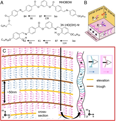
Banana-shaped molecules from two homologous series reported to exhibit the B7 phase were prepared to achieve the goal (Fig. 1A) (19–21). The molecular architectures with bent-core and flexible alkyl terminated tails exhibit smectic phases with molecules of spontaneously polar order (polar direction, p) and tilt (tilt direction, c) to make them chiral (Fig. 1B). In the B7 phase the inherent tendency of the polarization field to splay is strong enough that it appears in the form of linear stripes of the preferred sign of splay, separated by defect lines running parallel to the mean polarization direction (Fig. 1C). This in-plane modulation in the molecular orientation and ordering leads to a periodic pattern of layer undulations of wave vector q normal to p. The layer periodicity (layer spacing ∼4 nm) and the splay modulation periodicity (splay undulation period ∼50 nm) make the B7 a two-dimensionally ordered smectic.
Fig. 1.
Molecular structure of B7 smectic phase and ordering scheme. (A) B7 phase appears upon cooling from the isotropic phase (B) and is formed from the stacking of fluid layers of banana-shaped molecules, where the molecular long axis (n) is tilted (by angle θ) relative to the layer normal (s). In addition, polar order of the molecules leads to a polarization (p), the tilt of the molecular bows in the direction given by tilt direction (c); both are orthogonal to n and s. The polarization is spontaneously splay modulated, producing a periodic array of layer undulations and splay stripes. (C) Structure of the B7 phase of MHOBOW shows the stripe undulation, alternation of polarity and chirality, and two distinct types of defect lines [orange (trough) and brown (elevation) lines].
Depolarized Reflected Light Microscopy.
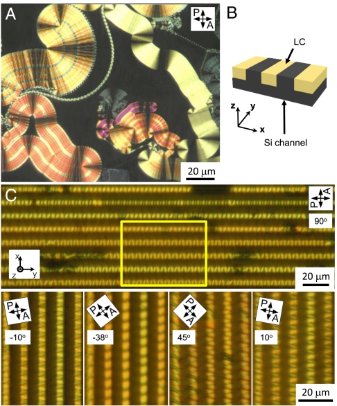
When a bent-core material transits into the B7 phase upon cooling from the higher temperature isotropic phase in a few-micron thick gap between glass plates, it generally appears in a spectacular display of beautiful twisted filaments, banana leaf-like domains, focal conic-like domains modulated by stripes, and checkerboard patterns, examples of which are shown in Fig. 2A (3, 5). The banana leaf and focal conic structures generally have the smectic layers locally normal to the plates. These domains are large enough that some information about their internal structure can be obtained with polarized light microscopy or microbeam X-ray diffraction, for example (3, 5, 6). However, attempts to produce macroscopically aligned B7 samples by surface treatment have not been successful, motivating our effort here with surfaces topographically structured on the micro-scale. Control of the texture of the B7 phase requires control of the spatial distribution of z, the layer normal as well as that of p and/or of its orthogonal companion q.
Fig. 2.
Sample preparation and optical structures with/without confined geometry. (A) In the planar aligned cell, the B7 smectic phase shows various kinds of domain morphology. (B) LC is filled in the silicon channels with 5 μm depth and 5 μm width, and the x-, y-, and z-direction is defined. (C) The confined B7 phase shows beautiful periodic optical textures. Clear dependence of the texture on polarizer orientation can be seen by rotating the sample, giving important information on molecular orientation. White letters indicate the rotating angle.
We tested channels with various widths (3, 5, 7, 10 μm, etc.), and the 5 μm channel showed the best results, though the 3 μm and 7 μm channels experiment also yielded similar morphology. In channels wider than 10 μm the bulk B7 structure starts reappearing with its own various complex structures. Based on this, micro-channels of rectangular grooves with 5 μm width (w) and depth (d) were made in the surface of single crystal Si substrates [(100) orientation] by conventional photolithographic masking followed by reactive ion etching with CF4 (22). In order to promote orientation of the layers locally normal to the plates, the resulting grooved surface is thoroughly cleaned by immersion in a mixture of DMF and methanol to remove organic-inorganic impurities, followed by rinsing several times with deionized water. The channels were filled with LC by heating the substrate surface (open to air) to a temperature in the isotropic range of the LC, putting a drop of LC on one end of the channel array, and letting capillarity draw the LC into the grooves. In a bent-core LC system, textures with the largest scale oriented domains are generally obtained by slow cooling (23). Thus, once filled the sample was then cooled at 0.02 °C/ min to form the B7 LC phase in the channels, and the resulting texture and ordering was probed by depolarized reflected light microscopy (DRLM). Comparison of the B7 DRLM textures obtained in the channels with those typically obtained on clean flat substrates (Fig. 2A) reveal a dramatic difference, with the topographic patterning generating highly regular patterns with periodic optical modulation along the channels (Fig. 2C and Fig. S1). The B7 layer and molecular orientation structures producing these patterns were probed by DRLM, SEM, and AFM and are reported below. We found that the B7 ordering of MHOBOW and 34-14O(OH)-4r is essentially the same under channel confinement.
SEM and AFM.
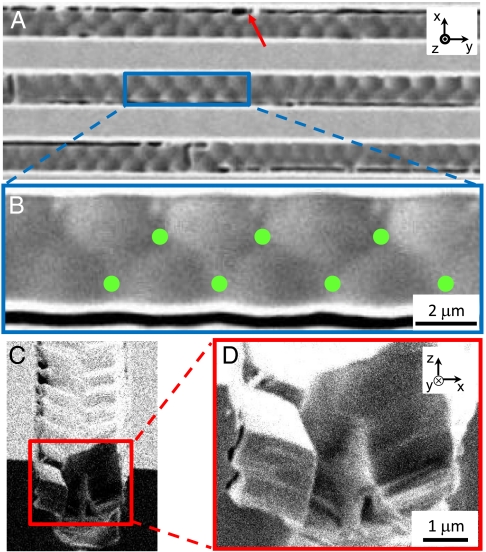
The smectic layering structure producing the periodic optical patterns along the channels was studied by SEM and AFM on MHOBOW samples by quenching the confined LC from the B7 temperature range by rapidly immersing it into liquid propane to trap the B7 structure, then warming it back to room temperature. For SEM such samples were then sputter-coated with a 5 nm thick layer of gold to enable visualization of its surface topography. Quenching of the LC was necessary because under slow cooling, transitions to other phases, such as the B4 (MHOBOW) and crystal (34-14O(OH)-4r), occurred (Fig. S2). The SEM and AFM images, typical examples of which are shown in Figs. 3 and 4, revealed a layer structure with a periodic pattern of long wavelength undulations along the channel, having a period consistent with that observed in the DRLM.
Fig. 3.
SEM images of confined B7 phase in 5 μm wide channels. (A) SEM shows topographical pattern with the same periodicity as found in the DRLM investigation Fig. 2C. (B) The magnified image of A shows what appears to be an array of truncated spherulitic domains in contact to form a periodic lattice along the channel. The green dots are the low points on the surface and the meeting points of three truncated spherulitic domains. (C and D) Cross-sectioned structure of one channel shows a preference for smectic layers to be normal to the channel surface. The dark lines (red arrow) are cracks appearing upon quenching of the sample for SEM, i.e., artefacts of the SEM sample preparation. The channel width (w), depth (d), and separation is 5 μm.
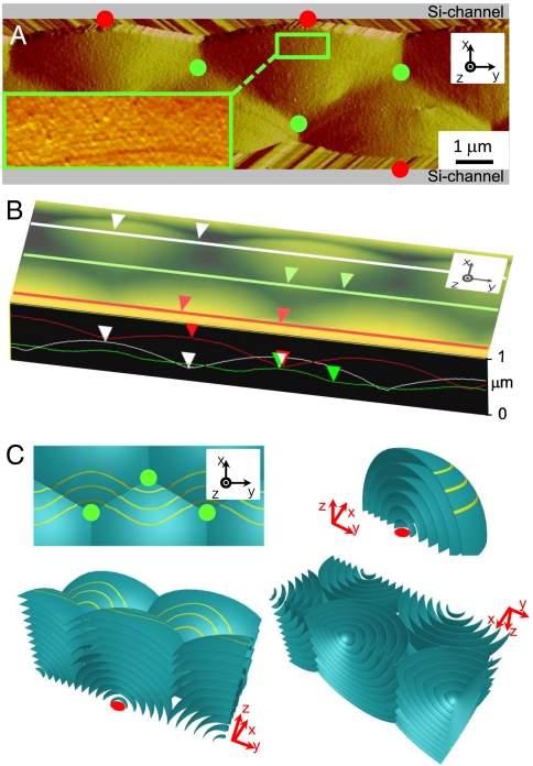
Fig. 4.
AFM micrograph and structural scheme of the channel confined B7 phase. (A) The long wavelength optical layer and undulation of Figs. 2 and 3 is visible, as well as the linear layering ripples of the polarization splay modulation. A red circle indicates the nucleation point of each domain. (B) Height mode AFM image shows the surface profile pattern clearly, with height difference of 300 nm between the high and low points. (C) Sketch of the proposed internal smectic layering structure generating the surface profile of B, consisting of a periodic array of spherulitic smectic focal conic domains that nucleate at the bottom corners of the channel, grow, and intersect. The top view shows the intersections of these domains and connection lines as found in SEM and AFM images. Three dimensional views from top and bottom of confined B7 phase show how these focal conic domains form in-channel. Yellow lines in top view are modulation lines of B7.
The internal structure of these periodic layering domains was revealed by examining SEM micrographs of cross-sectioned samples within the channel (Fig. 3 C and D). Fractured surfaces normal to the channel long axis, y, show that the layer alignment generally has the layers normal to the channel sidewalls and bottom and parallel to the LC/air interface. The accommodation of these preferences is via a periodic array of focal conic domains (FCDs), with cores alternating from one side of the channel to the other to form the periodic pattern. This structure is sketched in Fig. 4, showing the focal conic defects (FCD-II) (24) growing as sets of nested spheres from nucleation points on the bottom corners of the channels, which merge to give the smoothly undulating layer pattern near the top of the channel visible in Fig. 4. These domains grow as quarter spheres until they encounter one another, in which case they form interfaces along planar walls along the lines joining the green dots in Figs. 3B and 4 A and C. Such planar defects are not typically found in bulk smectic focal conic textures because they cost more energy than the line defects of Dupin cyclides (25), but, under conditions of strong confinement as is the case here, they can be maintained as evidenced by the planar chevron interface found in thin smectic C cells (26). In earlier studies of smectic A organization in channels, periodic arrays of toroidal (FCD-I) focal conic defects are observed. Toroidal FCD also satisfy the requirement for having the smectic layers at the channel surface normal to the interface. The appearance of spherulitic domains in the B7 case is likely related to a preferred layer orientation at the isotropic–smectic interface that is different from that of the SmA. In the B7, the appearance of fluid smectic filaments and conformal focal conic domains shows that the preference at the isotropic-B7 interface is to have the smectic layers parallel to the interface, which as Fig. 4C shows is the orientation required for the growth of spherulitic domains. In the SmA case the preference has the smectic layers normal to the isotropic-SmA interface, which leads to the formation of toroidal FCDs.
AFM visualization was carried out directly on the MHOBOW samples quenched in liquid propane and warmed to room temperature to probe their top-layer topography. Interestingly, in addition to showing the long wavelength undulation along the channel found in the SEM due to the periodic focal conics, the AFM revealed as well the short wavelength layer undulation due to the intrinsic polarization splay modulation (3) evident in Figs. 3 and 4. As evident in Fig. 4A the splay modulation (inset of Fig. 4A) and layer undulation crests run on average parallel to the channel, alternately shifting back and forth across the channel in phase with the underlying long wavelength undulations. This structure is sketched in Fig. 4C and Fig. S3, which also include the optical pattern (orange ellipses), the long wavelength undulation and splay modulation (yellow lines in top view of Fig. 4C), indicated by the yellow and orange lines. Thus, in the layers near the top of the channel, closest to the LC/air interface, the average orientation of the layer normal s is along the overall surface normal z, the average polarization orientation p is along the channel direction y, and the average orientation wave vector q of the polarization splay modulation is normal to the channel, along x.
The cross-sections in Fig. 4B show height profiles of surface of the long wavelength undulation pattern near the channel centerline (green) and edges (white, red), the latter showing that the maximum height difference is around 300 nm. The depth to the channel bottom from the high points of the red and white profiles is about 4 μm. This surface profile is substantially flatter than would be expected on the basis of the idealized structure drawing in Fig. 4C for a 4 μm depth (for which the height difference would be 1 μm). Surface tension, γ, can substantially flatten the surface undulations of wavevector, k of a smectic of compressional elastic constant, B, and depth d, when the ratio ρ = (B/2t)/(γk2) is small compared to 1. Estimates show that, in fact, ρ ∼ 103, indicating that topological defects, in this case edge dislocations, must appear in the smectic layering structure of Fig. 4C to flatten out the layers. Similar flattening is observed in the profiles of toroidal focal conic arrays (17). The splay modulation peak to valley amplitude is about 50 nm, comparable to that found by freeze fracture TEM and X-ray diffraction (Fig. S3) (3).
In the B7 splay modulated structure the in-layer plane principal axes of the optical dielectric tensor are along p and q. Thus the AFM finding of the wavy pattern of splay undulation stripes provides a ready explanation of the periodic patterns of birefringence found in DRLM. Thus, with polarizer and analyzer crossed and along y and x, respectively, as in Fig. 2A, we expect to see birefringent phase shift and thus depolarized reflection at places along the channel where the splay modulation stripes are rotated away from y, the periodic orange regions in Fig. S3 producing periodic bright regions along the channel. If the polarizer and analyzer are rotated, as in Fig. 2C, then the extinction bands become alternately brighter and darker, as would be expected for the splay stripe wave of Fig. 4C and Fig. S3.
Growing Sequence of B7.
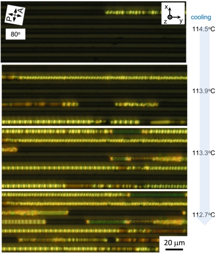
The creation of these periodic structures was investigated by DRLM observation during cooling from isotropic state (Fig. 5). As mentioned in Depolarized Reflected Light Microscopy, the periodicity of the channel confined structures becomes more perfect as the cooling rate is reduced, so that studies were carried out under conditions of very slow cooling, approximately 0.02 °C/ min. Fig. 5 shows a series of images of the sort typically obtained for MHOBOW and 34-14O(OH)-4r. Nucleation and growth of the B7 in the channels occurs independently in each channel, with typical characteristics as follows: (i) Periodic patterns with spacing comparable to the channel width are very common. (ii) In a given sample several different periodic patterns can appear, even in neighboring channels, distinguishable by periods of different length and domains of different birefringence. (iii) These patterns invariably grow from their ends, period by period. (iv) One kind of pattern can form and then be replaced by a second pattern as an interface between the two patterns moves along the channel. When this happens the second pattern typically has higher birefringence than the first. (v) The patterns, and thus we assume the B7 phase, nucleates in individual channels and different channels can have different nucleation temperatures, over a range of several degrees. All of these nucleation and growth phenomena are characterized by significant hysteresis and variability from channel to channel.
Fig. 5.
B7 smectic phase grown very slowly in the channels sometimes exhibits a periodic pattern that changes to a second periodic pattern by the passage of a defect moving along the channel. The boundary areas between B7 phase and isotropic phase show relatively large birefringence.
B7 ordering in domains of several different widths in the range of 3 μm < w < 10 μm and d = 5 μm were evaluated. For w < 7 μm the in-channel structure textures were similar to those reported here. For w > 10 μm forming of the bulk B7 growth morphologies begin to appear.
Discussion
The motif of linear growth along the channel suggests a heterogeneous nucleation and growth process in which existing B7 fosters the transition from the isotropic, and the period-by-period addition indicates that the preferential alignment of the B7 layers normal to the channel bottom and sides is best accommodated by three dimensional structures that are limited in size in all three directions to a dimension of the order of the channel width or depth. These structures are variations of focal conic defects, the preferred mode of filling space with curved smectic layers while limiting layer discontinuities to an array of line defects (17, 18). Such a motif has been found in smectic films with competing planar and homeotropic orientations on opposite surfaces and leads to linear periodic arrays of toroidal focal conic domains in channels with surfaces fostering planar alignment. The B7 focal conic domains in the channels have one conic section defect line on the solid channel surface and the other emerging from the LC/air interface to produce only weakly undulated top surface layers. The resulting three dimensional layer structures must then be dressed with the polarization and its splay modulation. How this is done is visible currently only for the layers near the air interface. In bulk B7 samples, freeze fracture TEM shows that in layers with curvature anisotropy, i.e., orthogonal directions of large and small radius of curvature that the polarization and splay stripes tend to orient to the direction of largest radius of curvature, while the splay modulation wave vector orients to that of smallest radius (Fig. 4) (27). These preferences appear to also be operative in the wave-like trajectory of the splay stripes of the channel confined B7 (Fig. 3A), as the stripes tend to follow contours of constant height of the top layer surface, avoiding the small curvature radii of the peaks and valleys.
The combination of the splay modulation and layer periodicity form a two dimensional rectangular lattice in MHOBOW. If the smectic layers have simple curvature in a plane normal to the modulation wave vector then this lattice can simply bend, as do the molecular stacks in the conformal domains commonly observed in columnar phases. With the smectic layering growing in spherulitic domains, however, the splay modulation must adjust itself to smectic layers having compound curvature, and it is not currently understood how this happens. The alignment in channels reported here will enable microbeam X-ray diffraction study of the organization of this modulation (28). Response of the B7 under conditions of channel confinement should also be of interest.
Materials and Methods
Preparing Confined Lamellae of Liquid Crystals.
Patterned silicon was fabricated on (100) Si wafers by using photolithography and reactive ion etching techniques. The patterns have a square cross-section with a certain depth 5 μm- depth and width. To control the surface anchoring, the glass and patterned surfaces were chemically cleaned by immersion in a mixture of dimethylformamide (DMF) and methanol to remove organic–inorganic impurity, followed by rinsing several times with deionized water. During the sample loading, the glass-patterned silicon hybrid cell equipped with a hot stage (INSTEC HCS410) and a controller (INSTEC STC 200) was heated to a temperature above the smectic–isotropic transition temperature to facilitate the flow of material into the channel.
DRLM, SEM, and AFM.
The optical anisotropic textures were observed under depolarized reflected light microscopy (DRLM) (Nikon Eclipse E400 POL). For SEM, confined LC films were quenched from B7 phase with liquid propane and coated with a 5 nm layer of gold, then were imaged using JSM-7401F (JEOL). Surface topology of the interface was performed under ambient conditions with an AFM (Nanoscope III: Veeco Instruments). The sample was prepared as shown above in the SEM description but not coated with gold. Then samples were glued to magnetic stainless steel discs, which were then attached to the piezoelectric tube scanner via an internal magnet on the scanner. To prevent deformation of the sample, contact mode AFM with Si3N4 cantilevers having a nominal spring constant of 0.06 N/m was used.
Supplementary Material
Acknowledgments.
This work was supported by the Materials Research Science and Engineering Centers program by National Science Foundation (NSF) Grant DMR-0820579, the I2CAM Junior Exchange Award by NSF Grant DMR-0645461 under ICAM-I2CAM. This work was performed in part at the University of Colorado’s Nanomaterials Characterization Facility.
Footnotes
The authors declare no conflict of interest.
This article contains supporting information online at www.pnas.org/lookup/suppl/doi:10.1073/pnas.1014593107/-/DCSupplemental.
References
- 1.Niori T, Sekine T, Watanabe J, Furukawa T, Takezoe H. Distinct ferroelectric smectic liquid crystals consisting of banana shaped achiral molecules. J Mater Chem. 1996;6:1231–1233. [Google Scholar]
- 2.Link DR, et al. Spontaneous formation of macroscopic chiral domains in a fluid smectic phase of achiral molecules. Science. 1997;278:1924–1927. doi: 10.1126/science.278.5345.1924. [DOI] [PubMed] [Google Scholar]
- 3.Coleman DA, et al. Polarization-modulated smectic liquid crystal phases. Science. 2003;301:1204–1211. doi: 10.1126/science.1084956. [DOI] [PubMed] [Google Scholar]
- 4.Jakli A, Krüerke D, Nair GG. Liquid crystal fibers of bent-core molecules. Phys Rev E. 2003;67:051702. doi: 10.1103/PhysRevE.67.051702. [DOI] [PubMed] [Google Scholar]
- 5.Jakli A, Lischka C, Weissflog W, Pelzl G, Saupe A. Helical filamentary growth in liquid crystals consisting of banana-shaped molecules. Liq Cryst. 2000;27:1405–1409. [Google Scholar]
- 6.Nastishin YA, Achard MF, Nguyen HT, Kleman M. Textural analysis of a mesophase with banana shaped molecules. Eur Phys J E. 2003;12:581–591. doi: 10.1140/epje/e2004-00030-7. [DOI] [PubMed] [Google Scholar]
- 7.Schadt M, Schmitt K, Kozinkov V, Chigrinov V. Surface-induced parallel alignment of liquid-crystals by linearly polymerized photopolymers. Jpn J Appl Phys. 1992;31:2155–2164. [Google Scholar]
- 8.Gibbons WM, Shannon PJ, Sun ST, Swetlin BJ. Surface-mediated alignment of nematic liquid-crystals with polarized laser-light. Nature. 1991;351:49–50. [Google Scholar]
- 9.de Gennes PG, Prost J. The Physics of Liquid Crystals. Oxford: Clarendon; 1993. [Google Scholar]
- 10.Vekris E, Kitaev V, Perovic DD, Aitchison JS, Ozin GA. Visulization of stacking faults and their formation in colloidal photonic crystal films. Adv Mater. 2008;20:1110–1116. [Google Scholar]
- 11.Janning JL. Thin-film surface orientation for liquid-crystals. Appl Phys Lett. 1972;21:173–174. [Google Scholar]
- 12.Berreman DW. Solid surface shape and alignment of adjacent nematic liquid-crystals. Phys Rev Lett. 1972;28:1683–1686. [Google Scholar]
- 13.Cheng J, Boyd GD. Liquid-crystal alignment properties of photolithographic gratings. Appl Phys Lett. 1979;35:444–446. [Google Scholar]
- 14.Jákli A, Krüerke D, Sawade H, Heppke G. Evidence for triclinic symmetry in smectic liquid crystals of bent-shape molecules. Phys Rev Lett. 2001;86:5715–5718. doi: 10.1103/PhysRevLett.86.5715. [DOI] [PubMed] [Google Scholar]
- 15.Yi Y, Nakata M, Martin AR, Clark NA. Alignment of liquid crystals by topographically patterned polymer films prepared by nanoimprint lithography. Appl Phys Lett. 2007;90:163510. [Google Scholar]
- 16.Fukuda J, Yoneya M, Yokoyama H. Surface-groove-induced azimuthal anchoring of a nematic liquid crystal: Berreman’s model re-examined. Phys Rev Lett. 2007;98:187803. doi: 10.1103/PhysRevLett.98.187803. [DOI] [PubMed] [Google Scholar]
- 17.Yoon DK, et al. Internal structure visualization and lithographic use of periodic toroidal holes in liquid crystals. Nat Mater. 2007;6:866–871. doi: 10.1038/nmat2029. [DOI] [PubMed] [Google Scholar]
- 18.Choi MC, et al. Ordered patterns of liquid crystal toroidal defects by microchannel confinement. Proc Natl Acad Sci USA. 2004;101:17340–17344. doi: 10.1073/pnas.0407925101. [DOI] [PMC free article] [PubMed] [Google Scholar]
- 19.Walba DM, et al. A ferroelectric liquid crystal conglomerate composed of racemic molecules. Science. 2000;288:2181–2184. doi: 10.1126/science.288.5474.2181. [DOI] [PubMed] [Google Scholar]
- 20.Yelamaggad CV, et al. A novel family of salicylaldimine-based five-ring symmetric and non-symmetric banana-shaped mesogens derived from laterally substituted resorcinol: synthesis and characterization. J Mater Chem. 2007;17:284–298. [Google Scholar]
- 21.Deb R, et al. Four-ring achiral unsymmetrical bent core molecules forming strongly fluorescent smectic liquid crystals with spontaneous polar and chiral ordered B7 and B1 phases. J Mater Chem. 2010;20:7332–7336. [Google Scholar]
- 22.Madou MJ. Fundamentals of Microfabrication. Boca Raton, FL: CRC; 2002. [Google Scholar]
- 23.Jákli A, Saupe A. Uniform bookshelf alignment of chiral smectic C films with guided backflow. J Appl Phys. 1997;82:2877–2880. [Google Scholar]
- 24.Kleman M, Lavrentovich OD. Soft Matter Physics. New York: Springer; 2003. [Google Scholar]
- 25.Pishnyak OP, Nastishin YA, Lavrentovich OD. Comment on “Self-organized periodic photonic structure in a nonchiral liquid crystal”. Phys Rev Lett. 93:109401–1. doi: 10.1103/PhysRevLett.93.109401. [DOI] [PubMed] [Google Scholar]
- 26.Clark NA, Rieker TP. Phys Rev A. 1988;37:1053–1056. doi: 10.1103/physreva.37.1053. [DOI] [PubMed] [Google Scholar]
- 27.Hough LE, et al. Chiral isotropic liquids from achiral molecules. Science. 2009;325:452–456. doi: 10.1126/science.1170028. [DOI] [PubMed] [Google Scholar]
- 28.Yoon DK, et al. Liquid crystal periodic zigzags from geometrical and surface anchoring induced confinement: Origin and internal structure from mesoscopic scale to molecular level. Phys Rev E. 82:041705. doi: 10.1103/PhysRevE.82.041705. [DOI] [PubMed] [Google Scholar]
Associated Data
This section collects any data citations, data availability statements, or supplementary materials included in this article.


