Abstract
This brief presents a standalone closed-loop wireless power transmission system that is built around a commercial off-the-shelf (COTS) radio-frequency identification (RFID) reader (TRF7960) operating at 13.56 MHz. It can be used for inductively powering implantable biomedical devices in a closed loop. Any changes in the distance and misalignment between transmitter and receiver coils in near-field wireless power transmission can cause a significant change in the received power, which can cause either a malfunction or excessive heat dissipation. RFID circuits are often used in an open loop. However, their back telemetry capability can be utilized to stabilize the received voltage on the implant. Our measurements showed that the delivered power to the transponder was maintained at 11.2 mW over a range of 0.5 to 2 cm, while the transmitter power consumption changed from 78 mW to 1.1 W. The closed-loop system can also oppose voltage variations as a result of sudden changes in the load current.
Index Terms: Closed-loop inductive power transmission, implantable biomedical devices, radio-frequency identification (RFID) reader
I. Introduction
Passive radio-frequency identification (RFID) tags and certain implantable microelectronic devices (IMDs) such as cochlear implants do not include batteries due to cost, size, weight, safety, and lifetime limitations. Inductive power transmission provides these devices with the required power on a continuous basis [1], [2]. In these systems, wireless power transmission across a pair of loosely coupled coils is preceded by a power amplifier (PA) in the external unit and followed by an efficient rectifier in the implanted unit to provide the IMD with an unregulated supply [3].
The coupling coefficient k between transmitter (Tx) and receiver (Rx) coils is the main factor in determining the amount of power that can be delivered to the IMD. Any changes in k can drastically change the received power. Misalignments and distance variations between the coils as a result of their relative movements are the main causes of variation in k. Changes in the received power can cause large voltage variations across the Rx coil. Load changes as a result of stimulation, for example, can also cause variation in the Rx coil voltage [4]. Such variations are highly undesired in IMDs because too little power can cause a malfunction, and extra power can increase heat dissipation within the implant and damage the surrounding tissue.
Therefore, stabilizing the IMD received power over a range of coupling and loading variations is imperative. One possible solution is to change the transmitted power in a closed loop in a way that the received power stays slightly above the minimum level that keeps the IMD operational [5]. Fig. 1 shows the simplified block diagram of such a closed-loop power transmission system. A back telemetry circuit based on load-shift keying (LSK) has been used to send information about the received power to the external transmitter. In the external unit, a detection circuit receives the back telemetry data, and a control unit provides the necessary voltage for a class-E PA through a dc–dc converter. Information about the received power can also be sent actively along with other biological data from the IMD to the outside of the body. In [6], the rectifier voltage in the IMD is compared with a reference voltage, and a power bit is generated, which is interleaved with the recorded data bits, and transmitted to an external receiver. In [7] a frequency control mechanism is used to regulate the power transferred to the implanted device. In this method, the change in the PA operating frequency mistunes the secondary coil and varies its received power.
Fig. 1.

Closed-loop inductive wireless power transmission across the skin.
In this brief, unlike the aforementioned examples, instead of developing a custom application-specific integrated circuit (ASIC) through a long and costly process, we are taking advantage of the built-in capabilities of a commercial off-the-shelf (COTS) RFID reader, i.e., TRF7960 (Texas Instruments, Dallas, TX), in the external unit to not only close the inductive power transmission loop through back telemetry but also drive the transmitter coil. This is a novel application for COTS RFID readers to be part of a standalone closed-loop wireless power transmission system. This is because, up until now, RFID systems have often been operated in an open loop for one-way data or power transmission. Since motion artifacts occur at low frequencies, the bandwidth offered by the COTS RFID back telemetry link (800 kb/s) is much higher than what is required for regulating the received power. Therefore, the excess bandwidth can be used for sending recorded biological information to the external unit.
Despite numerous publications on the closed-loop power transmission systems, only [5] has presented a control model. However, even in that paper, the authors have not considered the discrete-time nature of the control loop. Hence, the sampling frequency has not been considered in the stability analysis. We have derived a discrete-time model for the closed-loop system, which can more accurately predict the system closed-loop behavior in response to perturbations.
II. System Architecture
Fig. 2 shows a more detailed block diagram of the proposed RFID-based closed-loop power transmission system. It is composed of two main blocks: the power transmitter (external) and the transponder (IMD). Power is transferred from L1 to L2. The transponder generates a supply voltage for the other following blocks and uses LSK to send information about the received unregulated voltage (Vrec) back to the transmitter.
Fig. 2.
Block diagram of the RFID-based closed-loop power transmission system.
A. Transponder (IMD)
The transponder block consists of a rectifier, a regulator, an LSK circuit, and an ultra low power MSP430 microcontroller (Texas Instruments, Dallas, TX). A wideband full-wave rectifier is used to provide a dc voltage Vrec from the 13.56-MHz carrier. Vrec is divided (0.458 × Vrec) and compared with an internal MSP430 reference voltage Vref = 1.65 V. If the result is positive, i.e., Vrec > 3.6 V, then the LSK circuit sends short data bits back to the primary by closing M2 at a rate of 600 Hz. These pulses, which are short (30 μs) to prevent unnecessary power dissipation, indicate that the received power is more than enough. If the result of the comparison is negative, i.e., Vrec < 3.6 V, no data will be sent.
B. Power Transmitter
The transmitter sends power to the transponder and detects the back telemetry data to adjust its power level. We found an RFID reader to be a logical candidate for this purpose, particularly when it is all implemented in one chip, because it can both drive a coil and recover LSK back telemetry data. The TRF7960 RFID reader chip is equipped with a built-in class-D PA, which has a separate supply pin (TX_VDD) that controls its output power up to 200 mW. Due to the short distance between Tx and Rx coils, there was no need for an external PA after the RFID reader chip. We supplied the PA from a variable-output dc–dc converter (TPS61070) to control its output power. This dc–dc converter offers > 90% efficiency.
The control unit, which consists of an MSP430, a digital potentiometer, and the dc–dc converter, as shown in Fig. 2, increases the transmitted power by default with an adjustable step size unless LSK bits are received from the transponder. With back telemetry data present, the transmitted power is decreased with an adjustable step size until no more data bits are detected. In this case, the control unit once again increases the PA output power. In the steady state, without any external disturbance, the control unit maintains this up-and-down cycle to ensure that a constant power is delivered to the transponder, and Vrec is maintained around the designated 3.6 V.
In the presence of a disturbance, in the form of a change in the coils’ relative distance, alignment, or transponder loading, Vrec deviates from its nominal value, and the back telemetry data or the lack of them indicates whether the PA supply voltage should be decreased or increased, respectively. This will return Vrec back toward 3.6 V and stabilize the power transmission cycle around a new steady-state condition.
The dc–dc converter output voltage is proportional to its resistive feedback ratio. A counter in the digital potentiometer, driven by a 300-Hz clock form the microcontroller, normally counts up and increases the resistive ratio of the feedback loop. The 100-kΩ digital potentiometer can change TX_VDD from 3 to 5.5 V in 100 steps. Back telemetry data bits are detected by the RFID reader and sent to the microcontroller through the “Data Out” pin at 600 Hz. In the presence of these back telemetry pulses, the microcontroller changes the direction of the potentiometer counter, decreasing the feedback resistive ratio of the dc–dc converter and consequently reducing the TX_VDD voltage. The frequency of the back telemetry pulses should always be greater than the digital potentiometer counter frequency (300 Hz) to ensure that no back telemetry data are missed when updating the PA supply voltage.
Since the RFID reader is very sensitive to variations in the primary coil voltage envelope, any sudden changes in the voltage across L1 from the dc–dc converter can result in false data detection. Therefore, a low-pass filter has been added at the dc–dc converter output to filter the switching noise generated by the dc–dc converter.
III. System Modeling
We have modeled the closed-loop power transfer system in Fig. 2 for stability analysis. Although all the voltages and currents in the system are continuous in time, the closed-loop system operates in discrete time because the digital potentiometer counter clock cycles determine the timing of every change in the system variables. In Fig. 3, the system has been simplified and divided into four key building blocks: 1) the back telemetry circuit; 2) the control unit; 3) the RFID class-D PA and inductive link; and 4) the resistive–capacitive (RC) load following the rectifier circuit. The reference voltage Vref is the system input, and the rectifier voltage, Vrec is its output. The back telemetry circuit has been modeled by an adder, which compares Vref and Vrec. The control unit either increases or decreases the PA supply voltage according to the back telemetry data. Therefore, this unit is represented as an integrator, whose gain kI is determined by the number of digital potentiometer taps, i.e.,
Fig. 3.
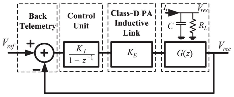
Closed-loop power transfer discrete-time model.
| (1) |
where x[n] is input to the control unit (i.e., back telemetry data), and y[n] is the output of the control unit, which is the PA supply voltage.
Because of the low back telemetry and power update frequencies and for simplicity, the class-D PA and inductive link are considered to be wideband and modeled only with a gain factor KE, which is the ratio of the average current delivered to the rectifier RC load (Ir) to the PA supply voltage. The rectifier capacitive Ic[n] and resistive IRL[n] load currents are given by
| (2) |
where T is the digital potentiometer counter clock period, Vrec[n] is the rectifier voltage at time t = nT, and q is the total charge stored in the rectifier capacitor. G(z), which is the impedance of the rectifier RC load, can be found from
| (3) |
Using (1)–(3), the closed-loop system transfer function in the Z-domain can be written as
| (4) |
which has two poles at
| (5) |
From basic control theory, a discrete-time system is stable if and only if every pole of its transfer function has a magnitude less than one, i.e., all poles must reside within the unit circle on the Z-plane. It can be shown that both poles in (5) are inside the unit circle, and the system is always stable. However, there are two different conditions for the system operation. If , then the poles are real, and the system is overdamped. Otherwise, the poles are complex and the system is under damped. The poles’ magnitude in this case can be found from (6), shown at the bottom of the page, which is obviously less than one.
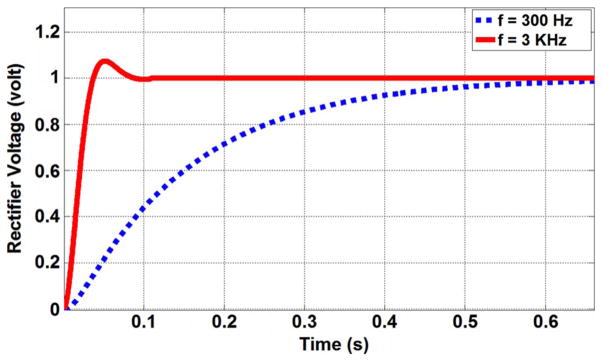
Using (5), it is possible to predict at what counter clock frequency 1/T the system is overdamped or underdamped. In our design, the loop response is overdamped for 1/T < 1.2 kHz. The normalized step responses of the closed-loop system for two clock frequencies of 300 Hz and 3 kHz are shown in Fig. 4. Our measurements support the accuracy of this simplified model. However, it should be noted that increasing the potentiometer clock frequency 1/T moves the poles closer to the unit circle and results in poor stability of the system.
Fig. 4.
Step response of the system for two counter clock frequencies.
IV. Measurement Results
Fig. 5 shows the RFID-based closed-loop wireless power transmission test setup. The TRF7960 maximum output power is 200 mW, which is sufficient for powering a virtual IMD with 10-mW power consumption at coil separations up to 2 cm. Two planar spiral coils were designed with their geometries optimized for fP = 13.56 MHz and a nominal relative distance of d = 1 cm (see Table I) and fabricated on FR4 printed circuit boards [8]. The coils were held in place using only nonconductive material (Plexiglas) and plastic screws to
Fig. 5.
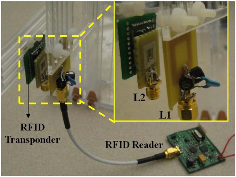
RFID-based closed-loop wireless power transfer measurement setup.
TABLE I.
System Specifications and Measured Results
| Parameters | Measured Values |
|---|---|
| Transmitter coil (L1) | Inductance = 0.4 μH |
| Outer diameter = 2 cm | |
| Inner diameter = 1 cm | |
| Number of turns = 4 cm | |
| Receiver coil (L2) | Inductance = 0.48 μH |
| Outer diameter = 1 cm | |
| Inner diameter = 0.6 cm | |
| Number of turns = 6 cm | |
| Power transmission frequency | 13.56 MHz |
| Back telemetry frequency | 600 Hz |
| Power update frequency | 300 Hz |
| Overall efficiency of the closed loop system (d = 1 cm) | 6.9 % |
| Overall efficiency of the open loop system (d = 1 cm) | 1.1 % |
| (6) |
eliminate eddy currents. On the transponder, a Vreg = 3.3 V regulator provides the MSP430 and a resistive load with a constant supply voltage, all of which consume 11.2 mW.
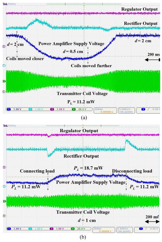
We used two methods to verify the functionality of the closed-loop system. First, we looked at variations in k by changing d and the coils’ alignment. Fig. 6(a) shows Vrec and Vreg on the transponder and PA supply voltage and L1 voltage on the transmitter side. When d = 2 cm, TX_VDD is 5.5 V, Vrec = 3.6 V, and Vreg = 3.3 V. In about 200 ms after the beginning of the trace, d is suddenly changed to 0.5 cm, while trying to maintain the coils’ alignment. As a result of this step increase in k, Vrec increases, while the closed-loop feedback starts reducing TX_VDD to oppose this perturbation.
Fig. 6.
Closed-loop power transmission system measured waveforms. (a) Changing the coils’ relative distance from 2 to 0.5 cm and the coupling coeficient. (b) Changing the transponder loading from 11.2 to 18.7 mW.
It takes ~0.4 s for Vrec to return back to 3.6 V and TX_VDD to settle in its new value, which is slightly more than 3 V. It can be seen that, as a result of increased k, the transmitted power has been decreased, and the system behavior is overdamped, as predicted by our model in Section III for 1/T = 300 Hz. ~1.1 s after the beginning of the trace, coils are returned back to their original position at d = 2 cm, resulting in TX_VDD returning back to 5.5 V as well. What is important is that, during all these changes, the first trace from the top in Fig. 6(a), which shows the transponder regulator Vreg, is maintained constant at 3.3 V. In this experiment, the ripple rejection capacitor after the rectifier was C = 10 μF (see Fig. 2).
Second, we observed the effects of changing the transponder loading RL on the closed-loop system. This was done by connecting and disconnecting a 1.45-kΩ resistor across the regulator output. RL changes the transponder power consumption from 11.2 to 18.7 mW. The transient response in Fig. 6(b) shows that the regulator and rectifier voltages slightly decrease by applying the load as the IMD power consumption suddenly increases (e.g., stimulation begins). It can be seen that TX_VDD increases to compensate for the higher power demand on the transponder side. Conversely, after disconnecting the additional load, all voltages return back to their original values. A voltage limiting or detuning circuit is needed before the rectifier to avoid large voltages across L2 when the coils move too close or when the IMD power consumption significantly drops, resulting in a sudden increase in the loaded quality factor of L2.
Power efficiency improvement is an added benefit of the closed-loop power transmission system. In an open-loop system, the transmitter power is always constant, while the received power can change as a result of variations in k and loading. To ensure functionality of the IMD in all conditions, the transmitter power should be high enough to energize the IMD in the worst-case scenarios such as the largest possible d, worst misalignments, or maximum loading. These result in poor efficiency when k is high or loading is low. To make things worse, the extra power is dissipated as heat on both Tx and Rx sides, increasing the risk of tissue damage. In a closed-loop system, however, the transmitter power is increased only as much as needed based on the k value and loading conditions.
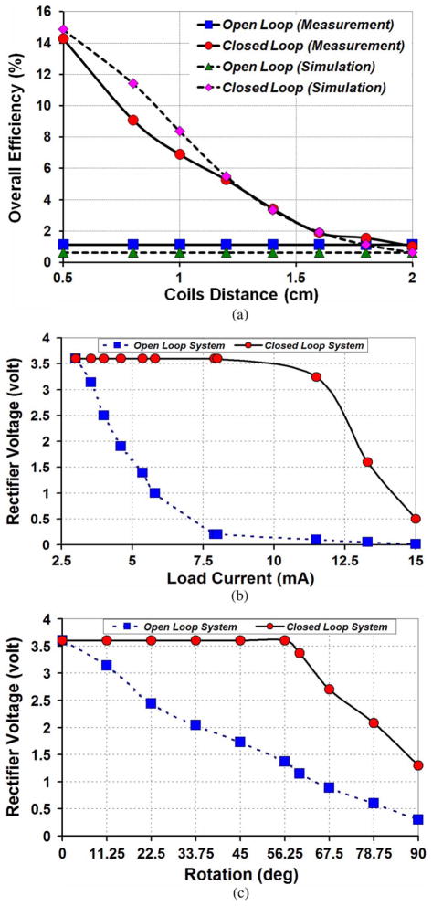
Fig. 7(a) compares the measured and simulated overall power efficiency values from the battery in the Tx unit to the transponder loading after the regulator (η% = ηdc–dc converter% × ηPA% × ηinductive link% × ηrectifier% × ηregulator%) for the open-loop and closed-loop systems. As expected, closed-loop power control has significantly increased η% when the coils are close to each other.
Fig. 7.
(a) Simulated and measured overall efficiency values versus the coils’ distance in open- and closed-loop conditions. (b) Open- and closed-loop load regulation. (c) Open- and closed-loop voltage variations vs. Tx coil rotations.
The load regulation capability of the system is demonstrated in Fig. 7(b). The closed-loop system increases the transmitted power to keep the rectifier voltage constant for loads up to 8 mA, which is the maximum power that Tx can provide in this system at d = 1 cm. In the open-loop system, Vrec decreases when the transponder load current increases because the transmitted power remains constant. Fig. 7(c) shows the performance of the closed-loop system compared to the open-loop system for the rotation of L1 with respect to L2 at d = 1 cm. In this case, the closed-loop system can tolerate rotations up to 56° with no change in the received voltage. Table I shows a summary of the RFID-based closed-loop power transmission system specifications and measurement results.
V. Conclusion
We have presented a standalone closed-loop wireless power transmission system to maintain the delivered power to a transponder, representing an IMD, constant over loading or coupling variations. Instead of designing a custom ASIC, we have taken advantage of a single-chip 13.56-MHz commercial RFID reader to send power and detect back telemetry data. The transponder, powered by the reader, returns data on the IMD received power. Our models and experimental results show that the system remains stable in all conditions. We have changed the coils’ distance from 0.5 to 2 cm, misaligned and rotated the Tx coil, and increased loading with no change in the transponder supply voltage. Using a closed-loop power transmission system for IMDs instead of designing an open-loop system based on worst-case scenarios can improve the power transfer efficiency by more than six times on the average.
Acknowledgments
The authors would like to thank U.M. Jow from the GT-Bionics Laboratory, School of Electrical and Computer Engineering, Georgia Institute of Technology, Atlanta, GA, for his help with the coil designs.
This work was supported in part by the National Science Foundation under Grant ECCS-824199 and in part by the National Institutes of Health under Grant 1R01NS062031-01A1. This paper was recommended by Associate Editor D. Heo.
Footnotes
Color versions of one or more of the figures in this paper are available online at http://ieeexplore.ieee.org.
References
- 1.Finkenzeller K. RFID—Handbook. 2. Hoboken, NJ: Wiley; 2003. [Google Scholar]
- 2.Catrysse M, Hermans B, Puers R. An inductive power system with integrated bidirectional data-transmission. Sens Actuators A, Phys. 2004 Sep;115(2/3):221–229. [Google Scholar]
- 3.Bawa G, Ghovanloo M. Active high power conversion efficiency rectifier with built-in dual-mode back telemetry in standard CMOS technology. IEEE Trans Biomed Circuits Syst. 2008 Sep;2(3):184–192. doi: 10.1109/TBCAS.2008.924444. [DOI] [PubMed] [Google Scholar]
- 4.Baker MW, Sarpeshkar R. Feedback analysis and design of RF power links for low-power bionic systems. IEEE Trans Biomed Circuits Syst. 2007 Mar;1(1):28–38. doi: 10.1109/TBCAS.2007.893180. [DOI] [PubMed] [Google Scholar]
- 5.Wang G, Liu W, Sivaprakasam M, Kendir GA. Design and analysis of an adaptive transcutaneous power telemetry for biomedical implants. IEEE Trans Circuits Syst I, Reg Papers. 2005 Oct;52(10):2109–2117. [Google Scholar]
- 6.Chaimanonart N, Zimmerman M, Young DJ. Adaptive RF power control for wireless implantable bio-sensing network to monitor untethered laboratory animal real-time biological signals. Proc IEEE Sensors Conf. 2008 Oct;:1241–1244. [Google Scholar]
- 7.Si P, Hu AP, Malpas S, Budgett D. A frequency control method for regulating wireless power to implantable devices. IEEE Trans Biomed Circuits Syst. 2008 Mar;2(1):22–29. doi: 10.1109/TBCAS.2008.918284. [DOI] [PubMed] [Google Scholar]
- 8.Jow UM, Ghovanloo M. Design and optimization of printed spiral coils for efficient transcutaneous inductive power transmission. IEEE Trans Biomed Circuits Syst. 2007 Sep;1(3):193–202. doi: 10.1109/TBCAS.2007.913130. [DOI] [PubMed] [Google Scholar]


