Abstract
Active illumination microscopy (AIM) is a method of redistributing dynamic range in a scanning microscope using real-time feedback to control illumination power on a sub-pixel time scale. We describe and demonstrate a fully integrated instrument that performs both feedback and image reconstruction. The image is reconstructed on a logarithmic scale to accommodate the dynamic range benefits of AIM in a single output channel. A theoretical and computational analysis of the influence of noise on active illumination feedback is presented, along with imaging examples illustrating the benefits of AIM. While AIM is applicable to any type of scanning microscope, we apply it here specifically to two-photon microscopy.
OCIS codes: (110.0180) Microscopy, (180.2520) Fluorescence microscopy, (180.5810) Scanning microscopy, (190.4180) Multiphoton processes
1. Introduction
Scanning fluorescence microscopy techniques such as confocal [1] and two-photon [2] microscopy have become indispensable tools in the biomedical community. In their conventional implementations, a laser beam of constant power is scanned through a sample, leading to a fixed illumination energy per pixel integration time. Recently, it has been shown that a dynamic control of the illumination energy per pixel integration time can lead to several benefits. For example, Controlled Light Exposure Microscopy (CLEM) [3], wherein the laser power is shut off once a prescribed amount of signal is detected from a given pixel, minimizes exposure of the sample to unnecessary illumination, leading to reduced photobleaching. Alternatively, a technique called Adaptive Illumination Microscopy (AIM) [4] operates by adjusting the laser power in an analog manner to maintain a constant signal level per pixel. The benefits of AIM are primarily the elimination of detector saturation, thanks to the ability of a feedback circuit to scale down the illumination power for bright objects, and an enhanced sensitivity to weak signals resulting from an increased illumination of dim objects. These two improvements can together be considered an enhancement of dynamic range. A difficulty with our previous implementation of AIM was that it required two detection channels, one for the signal and another for the laser power. We describe here a much more practical implementation of AIM that requires only a single detection channel, and can be operated as a simple drop-in addition to any standard scanning microscope, provided this is equipped with an analog laser power controller. Moreover, we equip our AIM microscope with direct log output to accommodate our enhanced dynamic range. While AIM is a general technique that can be applied to any scanning microscope, we apply it here specifically to two-photon microscopy, and provide a detailed theoretical description of the resultant benefits in signal to noise ratio (SNR) and dynamic range (DR). These results are corroborated with two-photon microscopy images of GFP labeled neurons in a mouse brain slice. Finally, we note that we have changed the name of our technique to Active Illumination Microscopy (still abbreviated AIM) to avoid confusion with adaptive optics, which is unrelated to this work.
2. Layout
The overall setup of the system is shown in Fig. 1. This is a conventional two-photon excited fluorescence (TPEF) microscope equipped with an electro-optic modulator (EOM, Conoptics 350-80) to control the laser power P. The amplifiers used in the feedback circuit are high bandwidth op-amps, primarily the Maxim Integrated Products MAX477 (300 MHz bandwidth) and the Texas Instruments OPA604 (20 MHz bandwidth). The bandwidth of the system is limited therefore by the EOM and not the electronics. The typical pixel rate of our TPEF system is approximately 100 kHz, while the EOM bandwidth approaches 1 MHz, allowing the circuit to rapidly control power on an intra-pixel time scale.
Fig. 1.
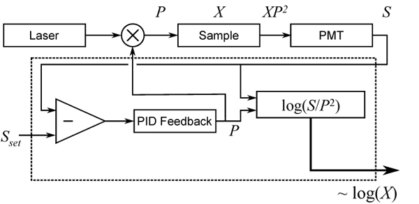
AIM layout for two-photon microscopy. Dashed line represents the integrated AIM instrument. Fluorescent output XP2 from a sample X is detected by a photomultiplier tube (PMT), producing a signal S that is maintained at a set point Sset by analog feedback to an EOM that controls the illumination power P. X is reconstructed and output on a log scale.
We define the fluorescent sample strength X to be a variable that includes all factors contributing to the local fluorescent emissivity, including concentration, cross-section, and quantum yield, such that the detected two-photon excited fluorescence is S = XP2. The feedback system, encased in the dotted line in Fig. 1, uses negative feedback to hold the detected fluorescence to a constant Sset by controlling the input illumination power, up to a user-defined maximum power Pmax. When sufficient power is available to hold Sset, the system is in “feedback-active” mode. When more than Pmax would be needed to reach Sset, the power is automatically set to Pmax and the system switches to “power-limited” mode. In either case, the desired quantity of interest is the sample strength X = S/P2. This is evaluated directly in the electronic instrument and supplied as an output. We emphasize that our feedback system is entirely self-contained here, and can be implemented in conventional TPEF microscopy as a simple add-on. The output of our instrument thus plays the role of the direct detector output of a conventional microscope.
The conversion to a single output instrument represents a practical improvement over our previous implementation of AIM [4] in which two output channels were recorded simultaneously (S and P) and image reconstruction was performed in software. Representing reconstructed AIM data in a single channel allows AIM to be more readily applied as a drop-in enhancement to a wider selection of instruments, since no software reconstruction is required to visualize the AIM image in real time, and not all microscope systems have two available input channels. However, care must be taken that the gain in dynamic range obtained by AIM not be undermined by a limitation in the dynamic range of the process itself of analog-to-digital conversion of our single output. In order to fully accommodate the enhanced dynamic range of our system, while maintaining the practicality of a single output, we decided to represent our reconstructed image (i.e. X) in logarithmic scale, achieved using Texas Instruments logarithmic amplifier TL441 (bandwidth = 40 MHz). On the log scale, the output of our AIM is given by
| (1) |
(Note: the factor of 2 is specific to two-photon excitation) On a linear scale, each successive step on the ladder represents an equal change in signal, whereas on a logarithmic scale each step corresponds to an equal change in decibels (or percentage) from the previous rung on the ladder. Consequently, on the low end of the range, the step size on the log-scale is much smaller than on the high end. The price of the low-end precision is degraded high-end precision. However, this is not a heavy cost. Though the signal-to-noise ratio of a shot noise-limited measurement scales with √N (where N is the number of detected photons for a given pixel), the overall noise increases at higher photon counts, also scaling with √N. Equal precision at the high range is therefore wasted, since the uncertainty in that range is higher anyway. A log-scale output is thus well-suited to AIM images, since this matches the characteristic of good low signal precision and high overall range. Additionally, from a practical standpoint, the reconstruction equation is more easily implemented in the electronics as a logarithm (subtraction) than on a linear scale (division).
Using a log scale amplifier alone without performing AIM will not increase dynamic range unless the limiting factor is the analog-to-digital converter, which is rarely the case. The dynamic range of the detector, which is usually the bottleneck, cannot be increased by processing the signal differently downstream. AIM is able to circumvent dynamic range limitations of the detector by allowing the illumination power to vary and carry information. We use the log amplifier to ensure that the new enhanced dynamic range is not lost when digitized by the computer.
It should be noted that whether data is represented in linear or log scale, it remains the same data (arguments related to SNR and dynamic range notwithstanding). Any subsequent conversion from log scale to linear scale, if desired, can therefore readily be performed a posteriori in software (we will be seeing examples of this in Section 5).
3. Principle of AIM
The shot-noise limited SNR’s for conventional and AIM systems are illustrated in Figs. 2a and 2b, respectively. We represent a minimum acceptable SNR (which may simply be 1, where signal begins to exceed noise) and a maximum SNR (due to saturation of the detector) as dashed lines. When the SNR is between these lines, we are within the dynamic range of our system.
Fig. 2.
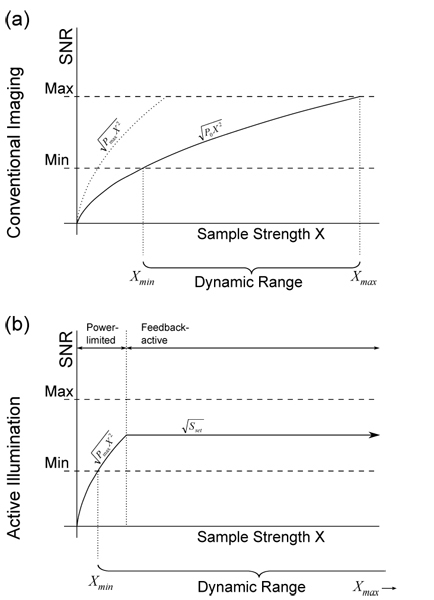
Signal to noise ratio (SNR) vs. fluorescent sample strength (X) under varying AIM settings. SNR follows standard shot noise model in the power-limited regime but is capped to a constant maximum once the system reaches Sset.
In a conventional TPEF system, the SNR rises proportionately with √X due to the properties of shot noise. Figure 2a provides an illustration of the dynamic range of the system when using an illumination power P0. Increasing power, up to the maximum available laser power, enables the measurement of lower values of X, but also lowers the saturation threshold. The dynamic range Xmax/Xmin of a conventional system remains constant regardless of power setting.
In an AIM system, there are two regimes of operation, as illustrated in Fig. 2b. A feedback circuit is designed to hold the detected signal at a user-defined set point, thus preventing the possibility of detector saturation. When the sample is strong enough for the set point to be attained, the system is said to be in feedback-active mode. On the other hand, if the sample is so weak that the maximum available power is insufficient to attain the set point, then the system switches to power-limited mode. When in power-limited mode, the AIM essentially behaves as a conventional system, but with an illumination power Pmax rather than P0, thereby enabling a measurement of the smallest possible Xmin.
The question arises as to what values should be used for and Sset and Pmax. When in feedback-active mode, the number of detected photons per pixel dwell time is held constant, and hence the shot-noise limited SNR is also held constant. The user can therefore select Sset based on a desired SNR performance. Since SNR is constant, noise becomes a constant fraction of the signal, which on the logarithmic scale is simply additive noise whose magnitude is independent of X. However, aside from preventing saturation, limiting signal output from a local region of the sample also limits phototoxic effects. Thus, while higher Sset improves the SNR in feedback-active mode, it also increases the potential for phototoxicity. Similarly, in power-limited mode, while a higher Pmax allows measurement of smaller X, it also increases the potential for photobleaching. Pmax is therefore practically limited not only by available laser power, but by the maximum permissible photobleaching.
It should be noted that photobleaching and phototoxicity are related but disparate phenomena. Photobleaching is the permanent transformation of a fluorophore into a non-fluorescent state [5], and phototoxicity refers to the adverse biological effects, usually caused by the generation of free radicals or singlet oxygen during fluorescent imaging [6]. For a given fluorophore species and excitation wavelength, photobleaching rate is determined primarily by illumination power (fluorophore concentration independent), whereas phototoxicity effects depend on total illumination absorption from a given volume (concentration and illumination dependent). A high concentration of fluorophores illuminated at low intensity will exhibit less photobleaching than a low concentration of fluorophores imaged under high excitation power such that the total fluorescent output is equal in both cases. However, both scenarios do result in equal phototoxicity.
In order to reduce phototoxicity in a conventional scanning fluorescence system, the only recourse is to reduce overall illumination power, the obvious cost of which is reduced SNR in regions of weak sample strength despite low risk of phototoxicity in these areas. On the other hand, with the AIM system, phototoxicity is constrained by Sset, whereas photobleaching, which becomes potentially problematic only when the sample strength is low, is constrained by Pmax. The proper choices of Sset and Pmax that maximize image quality while abiding by the constraints of phototoxicity and photobleaching thus ultimately depend on the sample in question.
We also note that while AIM provides a mechanism for limiting photobleaching by limiting Pmax, the same could be done on an ordinary TPEF microscope by simply turning down the power. If a sample can be imaged using standard TPEF using a given power level without saturation, AIM will not provide an improvement in image quality when Pmax is set to the same power level. Additionally, photobleaching in the focal plane may be somewhat nonuniform due to the varying illumination power, which may complicate the use of any photobleaching correction algorithms. However, AIM will still provide a reduction in phototoxicity, since any trouble areas that generate high fluorescent output per unit volume will receive reduced illumination.
4. Analysis of performance
In conventional imaging, the impact of noise sources such as electronic noise is well understood. However, with AIM, we must evaluate noise in the context of a closed-loop feedback system. We will assume that the detector introduces some amount of noise, represented by the random variable δS, such that the detected signal is Ŝ = GXP2+δS, where G is the detector gain. We also introduce a power-control noise δP that represents a discrepancy between the electronically measured signal P and the actual laser power leaving the EOM. Figure 3 shows the feedback system diagram with noise sources included.
Fig. 3.
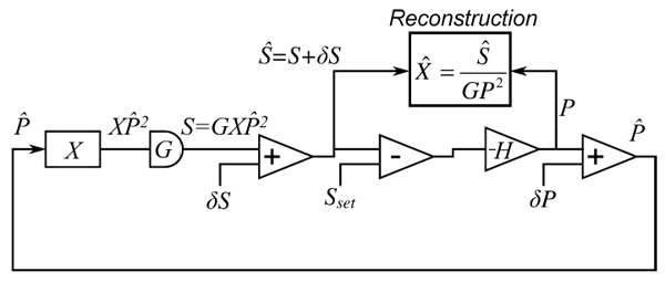
Block diagram of feedback circuit components with noise introduced.
The illumination power determined by the feedback system can be written as
| (2) |
where H is the transfer function of the feedback system. Taking the limit where H is very large, and using the approximation that δP is small compared to P, we have
| (3) |
Solving for P and ignoring the nonphysical negative solution leads to
| (4) |
We attempt to recover X using our noisy measurements of S and P to yield the reconstructed X̂:
| (5) |
We can rearrange the above in terms of the desired signal X:
| (6) |
Again using small noise assumptions while substituting in P from Eq. (4):
| (7) |
The SNR associated with our reconstruction of X is thus
| (8) |
where the noise standard deviations are defined by and .
From this equation, we see that the SNR from independent circuit noises scales with the set point Sset. When the detector noise is dominant over power-control noise (σS > σP), the SNR scales directly with Sset. When the reverse is true (σP > σS) the SNR scales with .
Let us compare this result with the SNR for a conventional TPEF microscope that uses a power P0 to image a fluorescence strength X. Before proceeding, we note that the noise σP can be broken down into two independent components: laser intensity fluctuations σPL and electronic measurement error σPM; σPL is common to both conventional TPEF and AIM, while σPM is unique to AIM. Using the same process as above, the SNR for conventional two-photon imaging can be shown to be
| (9) |
The ratio SNRAI/SNR0 should be greater than unity in order for AIM to yield an advantage. Using Eqs. 8 and 9, the ratio is
| (10) |
where
| (11) |
In Eq. 10, Sset/GXP02 is the ratio of the signals, and ξ is the ratio of the noises. The behavior of ξ depends on whether detector noise or power noise is more dominant. The best-case scenario is when σS is dominant, and ξ → 1. When the σP terms exceed σS, ξ scales with √X, reflecting the fact that AIM uses lower P for higher X, making this term more susceptible to fluctuations and noise.
If the power signal is known with perfect accuracy (i.e. σPM = 0), and the set point is fixed to same signal level recorded in conventional imaging (i.e. Sset = GXP02), then the SNR of AIM is identical to the conventional case, as expected.
We now evaluate the effect of this system on dynamic range (DR). DR is typically treated as the maximum recordable value divided by the minimum resolvable difference in values (which is often defined by noise rather than bit-depth). In a conventional configuration, the maximum measureable sample strength is Xmax = Smax/P02 where Smax is the output intensity at which detector saturation occurs. The minimum resolution is similarly σX = σS/P02. Thus, for conventional imaging the DR, defined by Xmax/σX, is given by
| (12) |
In AIM, saturation only occurs when the feedback circuit has already lowered P to the minimum resolvable value, which is σP, in order to hold S = Sset. Therefore Xmax = Sset/σP2. The minimum σX is defined the same way as in the conventional case, since at the low end of X the AIM system is power-limited while using constant illumination power Pmax, so σX = σS/Pmax2. The DR of AIM is then
| (13) |
The dynamic range enhancement of AIM therefore lies in the term (Pmax/σP)2, which is simply the dynamic range of the illumination power control system, with an extra power of 2 as a result of two-photon imaging. The last term, Sset/Smax, accounts for the eventuality that the full dynamic range of the detector is not used. That is, because of feedback, no value of S higher than Sset can occur. In practice, (Pmax/σP)2 can be several orders of magnitude while Sset/Smax can be set fairly close to 1 (limited only by the possibility of phototoxicity). That is, in practice the DR improvement obtained with AIM can be quite substantial, as we will see below.
5. Results
Imaging results in Fig. 4 demonstrate the advantages of AIM.
Fig. 4.
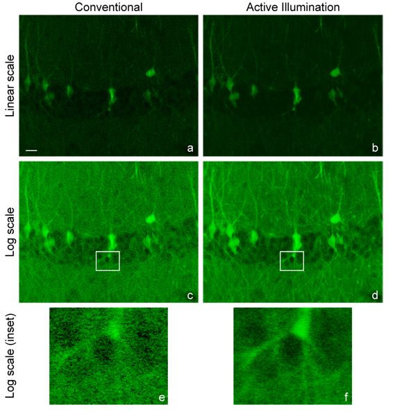
Image of mouse brain labeled with GFP (scale bar 20 μm). Conventional TPEF image, linear scale (a) and log scale (c). AIM image, linearized in software (b) and as acquired on log scale (d). Magnified insets of (c) and (d) shown respectively in (e) and (f). Video online of (a) to (d) showing a depth scan through 98 μm at a 2 μm spacing between slices.(Media 1 (2.3MB, AVI) )
The sample imaged is a mouse brain hippocampus labeled by cytoplasmic EGFP by in utero electroporation [7]. Figs. 4a and 4d are the unaltered images obtained with TPEF microscopy operated in standard mode (linear scale) and with AIM (logarithmic scale). These are the images as they are acquired by the user in real time. The log AIM image of course exhibits increased visibility in weakly fluorescent areas simply due to the logarithmic scale, however the benefits of AIM go much beyond this simple change of scale. The pixel rate on these images is 125 kHz, which is well within the roughly 1 MHz feedback system bandwidth.
To properly compare both images on the same scale, either a logarithm can be applied numerically to the conventional image, or an anti-logarithm can be applied numerically to the AIM image. For example, comparing both images on the logarithmic scale (Figs. 4c and 4d) demonstrates that the improvement from AIM is not limited to log-scale contrast. The application of a logarithm to the data from Fig. 4a produces Fig. 4c, but the simple emulation of the log lookup table does not duplicate the improved SNR available to the AIM system resulting from increased illumination power. While the total laser power available with or without AIM is unchanged, the maximum power that can be used in a conventional image is limited by saturation. For the conventional images in Fig. 4, the illumination power was set as high as possible without experiencing detector saturation (90 mW at 835 nm entering the scan head). AIM is able to use more power (220 mW) yet avoids saturation.
Alternatively, Fig. 4b shows the AIM image in 4d reconstructed on a linear scale. That is, once the data is collected on a logarithmic scale, the AIM image may be readily converted to a linear scale in software, with the same result that the effective dynamic range of the linearized image produced from AIM is higher than in the conventional linear image (Fig. 4a). Though not as obvious when presented on a linear scale, the SNR associated with dimmer regions appears superior when using AIM for the same reasons described above. In both AIM images, the transition between power-limited and feedback-active pixels is seamless and cannot be seen on the images.
The SNR improvement is also demonstrated in the power spectral density functions of an arbitrary line through the linear images, shown in Fig. 5. The ratio of the conventional to AI noise floor levels is 6.8, determined by averaging each power density function outside the spatial frequency kx = 1/6 pixels-1, where all of the power present is due to noise. This approximately corresponds to the ratio expected from the power increase when using AIM, which is (Pmax/P0)2 = 6.
Fig. 5.
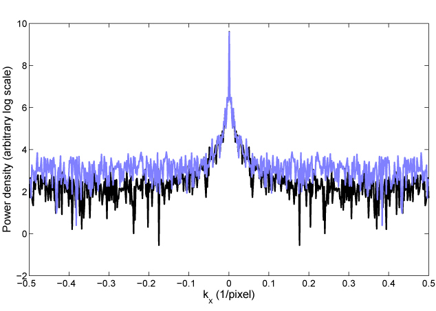
Line profile of power spectral density of images from Fig. 4a (conventional image, blue trace) and 4b (AIM image, black trace). Power density shown on a log scale against kx on x-axis and ky = 0. The noise floor for AIM (black) is lower than for normal imaging (blue), reflecting improved SNR.
Figure 4 primarily showcases the low-signal advantages of AIM when the conventional two-photon image is driven to the brink of saturation. To showcase the high-signal benefits, conventional two-photon microscopy is taken beyond the brink of saturation in Fig. 6 (top). The problem of saturation is completely remedied in Fig. 6 (bottom) where we observe that the AIM image not only avoids saturation in the strong sample regions but does so without sacrificing SNR in the weak sample regions.
Fig. 6.
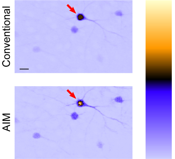
Image of GFP-labeled mouse neurons; conventional TPEF (top) cannot properly quantify what should be a bright neuron body indicated by arrow due to saturation. Saturation is avoided and the fluorescence of the neuron is properly captured in the linearized AIM image (bottom) without sacrificing SNR for dim objects. Arbitrary units of fluorescence are represented by a color look-up table (right) to highlight this effect; the bottom of the bar is zero fluorescence. Scale bar is 20 μm.
In summary, we have shown that our log-scale AIM system is able to confer dynamic range and exposure management improvements while using a single A/D channel. We demonstrate imaging results using TPEF microscopy. Additionally, since all of the components are integrated into a self-contained instrument, our AIM device can be easily applied to any scanning imaging system equipped with a fast modulator, such as a scanning confocal microscope equipped with acousto-optic modulator controlled laser illumination.
Acknowledgments
We thank Jinhyun Kim at the Janelia Farm Research Campus, Ashburn, VA for providing mouse tissue samples.
We gratefully acknowledge the NIH for partial support of this work.
References and links
- 1. Pawley J. B., Handbook of biological confocal microscopy (Springer, New York, 2006). [Google Scholar]
- 2. Denk W., Strickler J. H., Webb W. W., “Two-photon laser scanning fluuorescence microscopy,” Science 248, 73–76 (1990). [DOI] [PubMed] [Google Scholar]
- 3. Hoebe R. A., Van Oven C. H., Gadella T. W. J., Jr., Dhonukshe P. B., Van Noorden C. J. F., Manders E. M. M., “Controlled light-exposure microscopy reduces photobleaching and phototoxicity in fluorescence live-cell imaging,” Nature Biotechnology 25, 249–253 (2007). [DOI] [PubMed] [Google Scholar]
- 4. Chu K. K., Lim D., Mertz J., “Enhanced weak-signal sensitivity in two-photon microscopy by adaptive illumination,” Opt. Lett. 32, 2846–2848 (2007). [DOI] [PubMed] [Google Scholar]
- 5. Patterson G. H., Piston D. W., “Photobleaching in two-photon excitation microscopy,” Biophys. J. 78, 2159–2162 (2000). [DOI] [PMC free article] [PubMed] [Google Scholar]
- 6. Steinbauer M., Harris A. G., Abels C., Messmer K., “Charactierization and prevention of phototoxic effects intravital fluorescence microscopy in the hamster dorsal skinfold model,” Langenbeck’s Arch. Surg. 385, 290–298 (2000). [DOI] [PubMed] [Google Scholar]
- 7. Navarro-Quiroga I., Chittajalu R., Gallo V., Haydar T. F., “Long-term, selective gene expression in developing and adult hippocampal pyramidal neurons using focal in utero electroporation,” J. Neurosci. 27, 5007–5011 (2007). [DOI] [PMC free article] [PubMed] [Google Scholar]


