Abstract
A dual mode scanning acoustic microscope is investigated, yielding simultaneously images with optical and acoustical contrast. Short laser pulses are used to excite acoustic waves in a sample for the photoacoustic imaging mode. At the same time the pulses irradiate a conical target generating limited diffraction acoustic waves (X-waves) for large depth of field ultrasound imaging. For photoacoustic as well as for ultrasound imaging a focusing, ring shaped detector is applied. First phantom experiments demonstrate the possibility to acquire data for both imaging modes in a single scan, by separating images due to their different time of flight.
OCIS codes: (110.5120) Photoacoustic imaging, (110.7170) Ultrasound
1. Introduction
Combining two or more examination methods for medical imaging provides supplemental information for detection of tissue abnormalities. Because they use partly the same instrumentation but yield complementary imaging information, the combination of photoacoustic and conventional ultrasound imaging techniques in one device has recently received much attention [1]. Photoacoustic (PA) imaging uses the optical contrast of the examined object. Contrast is generated by absorption of pulsed light that propagates diffusely in the object [2]. Preferential heating and thermal expansion of structures with higher optical absorption compared to their surroundings cause broad band ultrasound waves, which are detected outside the object. Images reveal information about optical properties, but the applied technique is based on acoustic methods. On the other hand, classical ultrasound (US) imaging is based on the acoustic impedance contrast of observed targets. In the pulse echo mode, imaging information arises from backscattering of an incident ultrasound wave. To combine both imaging methods, the usual way is to add a pulsed laser source and an illumination system to a conventional ultrasound imaging device [1,3]. A drawback is the finite, often narrow bandwidth of the used piezoelectric transducers, which transmit and receive the ultrasound waves. They are not optimally suited for detection of photoacoustically generated ultrasound waves, which are intrinsically broadband.
An approach used both in PA and US imaging is the microscopy design, based on a fixed focus transducer that scans along the surface of the examined object and at each position samples a depth profile of back scattered or photoacoustically generated ultrasound signals. Images are formed by converting these amplitude (A-) scans into brightness values and arranging them column wise in an image array. The advantage of this approach is the possibility to optimize the transducer for this brightness (B-) scan mode in terms of sensitivity and resolution [4]. The frequently employed spherical lenses have a severe limitation, namely the trade off between lateral resolution and depth of field (DOF). Therefore, high resolution microscopes sometimes need depth scanning in addition to lateral scanning, which considerably increases the scanning time.
The solution proposed in this work addresses at the same time the limitations caused by bandwidth and DOF in a scanning, microscopic imaging device. By using a light pulse hitting an absorbing target for ultrasound generation we can employ the same wideband, receive-only sensors for both imaging modes. Furthermore, an axicon lens design for the generation and detection of ultrasound yields a large DOF.
2. Methods
2.1 Generation of focused ultrasonic pulses for the US mode
Ultrasound generation for the pulse echo mode is done by irradiating an absorbing target outside the object with a fraction of the laser pulse that is needed for PA excitation in the sample. For achieving a focused ultrasound field with higher DOF compared to a spherical lens, we use quasi diffraction free pulses, also called X-waves [5,6] generated on a conical target [7]. For manufacturing this special target we cut a negative cone into a piece of PMMA (polymethyl methacrylate). The surface of the cone was coated with black acrylic dye. By irradiating this so called axicon from the back with short laser pulses, focused broadband ultrasonic pulses are excited. In comparison to spherical ultrasonic lenses the depth of field is wavelength independent. It is only determined by the radius Rax and the angle ζ1 of the axicon transducer.
| (1) |
Figure 1 shows the setup of an axicon transducer. The lateral and axial widths of the center of the X-shaped acoustic wave pattern depend on the axicon angle and on an overall transfer function accounting for the finite laser light penetration into the acrylic dye and the finite laser pulse duration [8]. In the area of the focus the pressure is in the order of one bar.
Fig. 1.
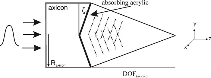
Layout of an axicon transducer. Laser pulses absorbed in a black layer on a conical surface give rise to acoustic waves that converge on an axis along a length given by the DOF.
2.2 Broadband focused piezoelectric detector for the US and PA mode
A thin piezoelectric polymer film (polyvinylidenfluoride - PVDF) was used for ultrasound detection. To optimize the bandwidth, the ultrasound transducer was only used to receive but not to transmit acoustic waves. The detector had a ring shape with inner and outer radii Ri and Ro. For achieving high resolution in a range along the ring axis, the detector was attached to a cone with an angle ζ2 (Fig. 2 ). The cone of the detector is made out of gray PVC with inserted aluminum electrodes. Due to the conical shape, waves emanating from the focal range had perpendicular or almost perpendicular incidence on the PVDF film. For the ultrasound detector used in this work the values were: ζ2 = 57°, Ri = 14.2 mm and Ro = 14.7 mm. By changing the sensor diameter and cone angle, the focal range can be slightly adjusted. The focal range of the detector, DOF(detector) was made to overlap with the focal zone of the axicon transducer [9]. Hence the same transducer could obtain information for both, the PA and US mode images simultaneously within one single scan.
Fig. 2.
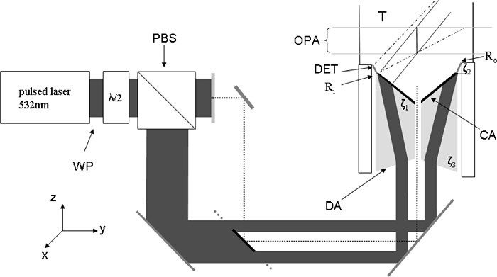
schematic experimental setup for dual mode scanning acoustic microscopy (DSAM): ring shaped illumination (IA) for the pulse echo-mode, free beam illumination (IP) for the photoacoustic mode; T: water filled tank; DET: piezoelectric ultrasound detector; CA: black coated axicon; DA: divergent optical axicon; OPA: operating area of the DSAM; Ri and Ro: inner and outer radii of the ultrasound detector.
2.3 Dual Mode Scanning Acoustic Microscope (DSAM)
The conical target and the piezoelectric ring detector were combined in the imager head as shown in Fig. 2. The laser pulse energy between the two imaging modes was split using a half wave plate and a polarizing cubic beam splitter. By rotating the half wave plate a continuous tuning of the pulse energy ratio between the photoacoustic (IP) and laser ultrasound (IA) illumination paths was possible, depending on the observed targets. The separated illumination paths were made collinear using a glass plate with a small, circular mirror made of a deposited gold layer. The imager head combined an optical and an acoustical axicon, both made of optically transparent polycarbonate (PC) with conical shape. The latter was coated with black acrylic paint as optical absorber for the excitation of broadband acoustic pulses (Fig. 2) as described in Section 2.1. The radius Rax of the axicon was 14 mm and the axicon angle ζ1 was 28°. The optical axicon with an angle ζ3 generated a ring shaped illumination pattern on the optical absorber. This created the X-wave only along a part of the axis, in the range of highest resolution of the piezoelectric ring detector. Operating in the acoustic mode, the photoacoustically excited X-wave propagates to an object and is reflected or backscattered due to the impedance variations in the object or between object and the surrounding water.
For the photoacoustic mode a laser beam propagating through a small hole in the device illuminated the sample. Both, the back scattered wave and the wave created by absorption directly in the object were detected by the piezoelectric ring sensor described above, which was mounted coaxially to the acoustic axicon. Due to the different materials of the axicon transducer (transparent polycarbonate) and of the detector (gray PVC) no direct light can be incident on the PVDF. Figure 2 illustrates the common operating area, as well as the illuminated ring pattern for exciting the X-waves. This common focal area, which has a length in the range of 10 mm represents the operating range of the microscope.
An acoustic source, either a small optical absorber or a small acoustical scatterer, located on this focal line gives rise to a single peak in the received signal. For a source laterally displaced from the focus the signal splits into two pulses (Fig. 3 ). Assuming a point source within the focal area with both, acoustic and optical contrast, the time delay between the received acoustic and photoacoustic signals is defined by the ring detector radius and the geometry of the absorbing axicon. The pulse-echo signal has an almost two times longer time of flight than the photoacoustic signal (see Fig. 3). Hence, PA and US signals are well separated. For an extended object, the US signal from the point on the axis closest to the detector should arrive later than the PA signal from the farthest point. For image acquisition the specimen is scanned in direction perpendicular to the transducer axis across the sample. The received signals are then separated in PA and US A-scans and converted from time into true depth axis.
Fig. 3.
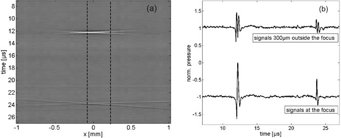
(a) Cross section image of a horse hair (b) temporal signals in and 300µm outside the focus, at the positions marked in (a) with dashed lines.
The width and the angle of the detector influence its lateral and axial resolution. In the pure acoustic mode also the angle of the axicon transducer influences resolution.
3. Results
A horse hair phantom was used to demonstrate the separation of the acoustic and the photoacoustic signal. In the experiment laser pulses with 10 ns duration coming from the frequency doubled output (532nm) of a Nd:YAG laser system were used to illuminate the black coated axicon and the observed target. Figure 3a shows an image composed of the full A-scans. The scan direction was oriented perpendicular to the hair. The photoacoustic signal appears at t = 12 µs. The acoustic signal is identified at approximately t = 23 µs. Figure 3b shows two A-scans at the positions indicated as dashed lines in image 3a. The signal in the focus (lower trace) has higher amplitude than the signal outside the focus. Furthermore, a transition of one single signal inside the focus to two separated signals outside the focus can be seen. This separation gives rise to the X-shaped images of the hair.
To investigate both contrast mechanisms in a simultaneously acquired image we used a phantom consisting of a black horse hair loop which had been glued onto the bottom of a plastic tube. The horse hair had a diameter of about 150 µm and the plastic tube had a diameter of 9 mm. The horse hair exhibited at the same time photoacoustic and pure acoustic contrast.
The plastic tube had almost no optical absorption; hence it was a purely acoustically visible object. Scanning was performed in the plane perpendicular to the transducer axis in step sizes of 100 µm and 50 µm in x and y direction, respectively. To save acquisition time, the step size in the (manually scanned) x direction was larger but still below the anticipated resolution limit. For illumination we used again pulses from a Nd:YAG laser with an excitation wavelength of 532 nm and pulse duration of 10 ns. For data acquisition an amplifier with a bandwidth from DC to 14 MHz was used. Hence a time increment of 40 ns was sufficient. Figure 4 shows the maximum amplitude projections in direction of the transducer axis for the acoustic and photoacoustic time windows. The limits of the photoacoustic time window were chosen from 11.53 µs to 12.17 µs and for the pure acoustic image from 22.33 µs to 22.96 µs. Due to the small dimensions of the phantom only narrow time windows were chosen. As expected, in the acoustic image the horse hair and the plastic tube can be observed. Photoacoustically, only the horse hair loop appears (Fig. 4).
Fig. 4.
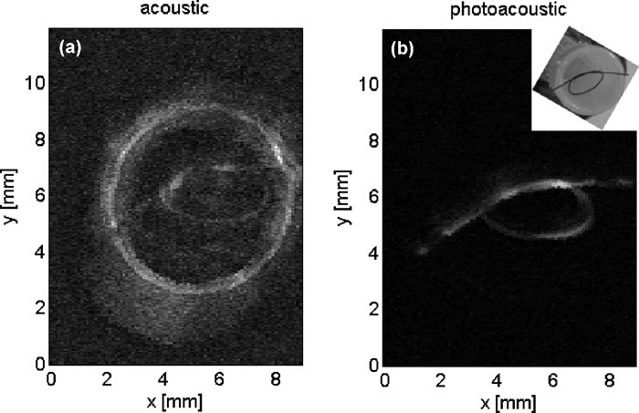
Maximum amplitude projection images of the acoustic mode (left) and the photoacoustic mode (right) of the horse hair phantom (see inset)
In the photoacoustic and acoustic projections the overlapping area of the hair loop appears brighter and broader (y ~7 mm). In the images, the typical width of the hair is ~150 µm in the acoustic mode and 250 µm in the photoacoustic mode. Considering an actual width of ~150 µm of the hair, the resolution can be estimated to lie in the range of 150 µm. The acoustic resolution is higher, as a result of a multiplication of the focusing patterns of transducer and detector. The photoacoustic resolution is mainly determined by the resolution limit of the detector. Furthermore the contrast mechanisms are different. To investigate the resolution in z-direction for the pulse-echo imaging mode we used a crossed hair phantom as an object. The hairs (diameter 150 µm) were suspended in a plane perpendicular to the transducer axis (the x-y-plane). Again, scanning was performed over an area perpendicular to the transducer axis in step sizes of 100 µm and 50 µm in x and y directions, respectively. Each of the two crossed hairs was located at a slightly different z-position. This is can be seen in Figs. 5a and 5b, showing each hair separately at true depth relative to the upper edge of the transducer plane. A maximum amplitude projection in z-direction is shown in image 5c. The resolution in z-direction is in the range of 100µm.
Fig. 5.
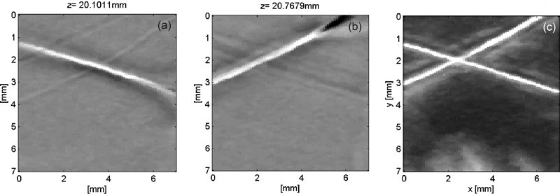
(a,b): Section images perpendicular to the z-axis at two depths, showing each horse hair separately. (c) Maximum amplitude projection in z-direction.
4. Discussion
The main feature of the presented imaging device is the fact that both, the acoustic waves for ultrasound imaging and for photoacoustic imaging, are generated by the same short laser pulse. With this concept the same broadband acoustic detector can be used for photoacoustic and ultrasound signals. If this detector is based on some kind of optical sensing principle, an entirely optical transducer can be made without any electrical connection. A possible implementation is the use of an optical, interferometric fiber sensor [10,11]. The images in Fig. 3 show that a small object like the cross section of the horse hair appears as an “X”. Although the exact position of the object can be obtained from the intersection point of the two lines forming the X, these artefacts may cause ambiguities in complex objects. A single ring detector as well as a conical detector cause this kind of side lobes [9,12]. Double ring sensors [13] or some kind of deconvolution [9] may help reducing the artefacts. An even better result is expected from an annular array for dynamic focusing. An expected benefit of the axicon imager design is the extended DOF. The depth positions of the presented specimens were 13 mm for the hair loop, 17 mm for the single hair and about 21 mm for the crossed hair phantom. To use the full available DOF of the axicon transducer the detector has to be adapted. As expected, the acoustic images show higher resolution but lower contrast. The resolution is in the range of 150 µm but can be enhanced with an annular detector array.
5. Conclusion
In conclusion, the presented setup allows simultaneously to record photoacoustic and ultrasonic A-scan data from the same object. It is therefore useful for imaging tasks where both optical and acoustical contrast is present. Using the technique of limited diffraction beams extends the depth of field, making possible the simultaneous imaging of shallow and deep structures with comparable resolution.
Acknowledgments
This work has been supported by the Austrian Science Fund FWF Project Nos. L418-N20 and S10502-N20.
References and links
- 1.Niederhauser J. J., Jaeger M., Lemor R., Weber P., Frenz M., “Combined ultrasound and optoacoustic system for real-time high-contrast vascular imaging in vivo,” IEEE Trans. Med. Imaging 24(4), 436–440 (2005). 10.1109/TMI.2004.843199 [DOI] [PubMed] [Google Scholar]
- 2.Xu M. H., Wang L. V., “Photoacoustic Imaging in Biomedicine,” Rev. Sci. Instrum. 77(4), 041101 (2006). 10.1063/1.2195024 [DOI] [Google Scholar]
- 3.Harrison T., Ranasinghesagara J. C., Lu H., Mathewson K., Walsh A., Zemp R. J., “Combined photoacoustic and ultrasound biomicroscopy,” Opt. Express 17(24), 22041–22046 (2009). 10.1364/OE.17.022041 [DOI] [PubMed] [Google Scholar]
- 4.Zhang H. F., Maslov K., Stoica G., Wang L. V., “Functional photoacoustic microscopy for high-resolution and noninvasive in vivo imaging,” Nat. Biotechnol. 24(7), 848–851 (2006). 10.1038/nbt1220 [DOI] [PubMed] [Google Scholar]
- 5.Lu J. Y., Greenleaf J. F., “Nondiffracting X waves-exact solutions to free-space scalar wave equation and their finite aperture realizations,” IEEE Trans. Ultrason. Ferroelectr. Freq. Control 39(1), 19–31 (1992). 10.1109/58.166806 [DOI] [PubMed] [Google Scholar]
- 6.Lu J. Y., Greenleaf J. F., “Experimental verification of nondiffracting X waves,” IEEE Trans. Ultrason. Ferroelectr. Freq. Control 39(3), 441–446 (1992). 10.1109/58.143178 [DOI] [PubMed] [Google Scholar]
- 7.Passler K., Nuster R., Gratt S., Burgholzer P., Paltauf G., “Laser-generation of ultrasonic X-waves using axicon transducers,” Appl. Phys. Lett. 94(6), 064108 (2009). 10.1063/1.3083550 [DOI] [Google Scholar]
- 8.Passler K., Nuster R., Gratt S., Burgholzer P., Paltauf G., “Photoacoustic Generation of X-waves and their Application in a Dual Mode Scanning Acoustic Microscope,” Proc. SPIE 7371, 73710R (2009). [Google Scholar]
- 9.Gratt S., Passler K., Nuster R., Paltauf G., “Photoacoustic imaging using a conical axicon transducer,” Proc. SPIE 7371, 73710W (2009). [Google Scholar]
- 10.Berer T., Gruen H., Hofer C., Burgholzer P., “Photoacoustic microscopy with large integrating optical annular detectors,” Proc. SPIE 7371, 73710X (2009). [Google Scholar]
- 11.H. Gruen, T. Berer, R. Nuster, G. Paltauf, and P. Burgholzer, “Fiber-based Detectors for Photoacoustic Imaging,” Proc. SPIE 73710T (2009). [DOI] [PubMed] [Google Scholar]
- 12.Paltauf G., Gratt S., Passler K., Nuster R., Burgholzer P., “Photoacoustic imaging with limited diffraction beam transducers,” Proc. SPIE 7177, 77170S (2009). [Google Scholar]
- 13.Kolkman R. G. M., Hondebrink E., Steenbergen W., van Leeuwen T. G., de Mul F. F. M., “Photoacoustic imaging of blood vessels with a double-ring sensor featuring a narrow angular aperture,” J. Biomed. Opt. 9(6), 1327 (2004). 10.1117/1.1805556 [DOI] [PubMed] [Google Scholar]


