Abstract
Background
Increasingly, acetabular retroversion is recognized in patients undergoing hip arthroplasty. Although prosthetic component positioning is not determined solely by native acetabular anatomy, acetabular retroversion presents a dilemma for component positioning if the surgeon implants the device in the anatomic position.
Questions/purposes
We asked (1) whether there is a difference in ROM between surface replacement arthroplasty (SRA) and THA in the retroverted acetabulum, and (2) does increased femoral anteversion improve ROM in the retroverted acetabulum?
Methods
Using a motion analysis tracking system, we determined the ROM of eight cadaveric hips and then created virtual CT-reconstructed bone models of each specimen. ROM was determined with THA and SRA systems virtually implanted with (1) the acetabular component placed in 45° abduction and matching the acetabular anteversion (average 23° ± 4°); (2) virtually retroverting the bony acetabulum 10°; and (3) after anteverting the THA femoral stem 10°.
Results
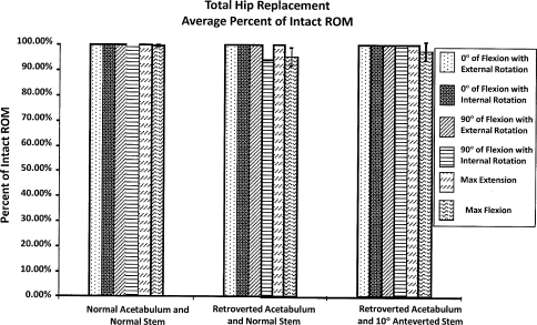
SRA resulted in ROM deficiencies in four of six maneuvers, averaging 25% to 29% in the normal and retroverted acetabular positions. THA restored ROM in all six positions in the normal acetabulum and in four of the six retroverted acetabula. The two deficient positions averaged 5% deficiency. THA with increased femoral stem anteversion restored ROM in five positions and showed only a 2% deficiency in the sixth position. Compared with the intact hip, ROM deficits were seen after SRA in the normal and retroverted acetabular positions and to a lesser extent for THA which can be improved with increased femoral stem anteversion.
Conclusion
Poor ROM may result after SRA if acetabular retroversion is present.
Introduction
Acetabular retroversion is increasingly being recognized in patients undergoing hip arthroplasty [4, 14]. Retroversion of the acetabulum has been associated with labral tears, femoral acetabular impingement, and the development of hip arthritis [1, 2, 12]. Patients may present earlier in life with degenerative hip disease for which hip arthroplasty may be recommended. Although THA predictably restores durable pain relief and function in patients with hip arthritis, SRA has been increasingly popular, especially for younger patients because of the perceived benefits of improved hip function, preservation of bone stock, and increased stability [8]. Another reported benefit of SRA is the large head, which has been associated with a decreased risk of dislocation (4% vs 0%) [11] and improved ROM (hip flexion 98° vs 112°) measured by physical examination [15].
Soft tissue impingement or restrictions resulting from fat, muscles, or capsular ligaments can limit hip motion before any prosthetic impingement. Computer simulations overestimate in vivo hip ROM because there are no soft tissue restrictions [8]. Although implant, bone, or soft tissue can limit motion, these factors become less important if they occur at positions that the patient cannot reasonably expect to achieve. Hip ROM studies show limitation of motion occurs for hip flexion more than hip extension [10]. Recently, we reported a comparison of prosthetic hip ROM with the normal hip in a cadaveric model with intact soft tissues [5]. These data showed decreased hip ROM, particularly flexion, for SRA compared with THA.
However, ROM studies generally examine only normal hips, and not those with retroversion. With a retroverted acetabulum, the anterior wall of the acetabulum protrudes more than the posterior wall. Acetabular implant placement is not straightforward in this situation. If the surgeon’s goal is to place the component parallel with the anterior and posterior walls of the acetabulum, then posterior hip instability may result. Alternatively, if a surgeon places the acetabular component in a predetermined position (45° abduction/20° anteversion), then a substantial portion of the acetabular component will be uncovered posteriorly.
We therefore asked two questions: (1) Is there a difference in ROM between SRA and THA in the retroverted acetabulum; (2) Does increased femoral anteversion improve ROM in the retroverted acetabulum?
Materials and Methods
This experimental study was performed as a combination of cadaveric and computer simulation. We developed a method to physically simulate the kinematics of the normal intact hip through application of standard loading conditions across cadaveric hips in multiple positions encompassing the arc of motion. Using computer reconstructions of the same specimens, we virtually implanted THA and SRA components in precisely controlled positions and orientations. The physical maneuvers performed on each cadaver then were repeated virtually using the implanted computer model to determine whether normal joint motion could be replicated without impingement. The bony acetabulum of the virtual models then was retroverted 10º using computer simulation and component placement and impingement measurements were repeated. Finally, the impingement maneuvers were repeated in the cases with the THA but with 10º of increased femoral stem anteversion.
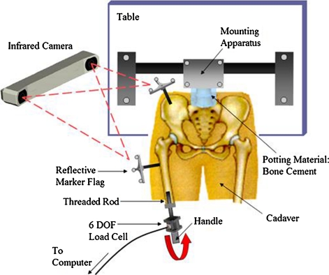
Eight cadavers (average age, 74.3 ± 18.3 years) were harvested beneath the L5 vertebra to obtain fresh-frozen lower extremity specimens. The femurs underwent a pathologic screening process for decreased neck-shaft angles, head-to-neck ratios less than 1.2, and any other abnormalities that potentially could eliminate the option to resurface. We used CT of each hip to view the distal pelvis and distal and proximal femur at 1.25-mm slices, and each femur was cut at approximately half the distance between the head and distal condyles. To provide full hip extension, the lumbar spine was potted in bone cement and mounted in a customized holding apparatus that lifted the pelvis free of the examination table. A six-axis load cell was mounted on the distal cut end of each femur through an intramedullary rod. Each cadaveric spine was secured in the holding apparatus in the supine position (Fig. 1). For motion analysis tracking, metal brackets supporting an array of three precisely placed reflective markers were attached to the pelvis and femur.
Fig. 1.
A diagram of the intact cadaveric testing apparatus (not to scale) is shown. Using a 3-D motion analysis system, each position of the bone was tracked while applying torque on the femur through a load cell.
Next, we placed both femurs in 12 unique positions of internal/external rotation (IR/ER), abduction/adduction (AB/AD), and flexion/extension (F/E) until they reached the limit of motion. For ease of presentation, six maneuvers were measured (Table 1). This limit of motion was established for each maneuver based on its position after applying 100 Nm (calculated from the load cell) to the hip while using a three-dimensional (3-D) motion analysis system (Polaris, NDI, Waterloo, Ontario, Canada) to track the reflective markers on each bone for a more accurate position.
Table 1.
The six measured impingement maneuvers
| Anterior impingement | Posterior impingement |
|---|---|
| Internal rotation at 0° | External rotation at 0° |
| Internal rotation at 90° | External rotation at 90° |
| Maximum flexion | Maximum extension |
Computer models of each specimen’s bony anatomy were generated by reconstructing CT Dicom files of the pelvis and femurs of each hip. The soft tissues of each hip were not reconstructed owing to the difficulty in simulating their structures.
Based on those models, we calculated morphologic descriptors of the femur and pelvis using axes defined by bony landmarks according to Beaule et al. [1]. Descriptors derived from each reconstruction included the intact subchondral head size, the head-to-neck ratio, the neck/shaft angle, and femoral anteversion.
The starting position of the pelvis was configured based on a vertically oriented pubic symphysis and a plane tangent to the anterior surfaces of both anterior-superior iliac spines. By creating a vector joining the anterior-superior iliac spines, a horizontal (medial-lateral) pelvic axis could be established. The initial femoral orientation was created in terms of: (1) neutral F/E, defined by aligning the vertical axis of the pelvis and the line tangent to the posterior cortex at the midlength of the diaphysis; (2) neutral adduction, defined by orienting the epicondylar axis of the femur parallel to the horizontal plane; and (3) neutral axial rotation, defined by aligning the posterior condyles and the vertical, coronal plane. Using custom software (Fig. 2), we measured the limit of motion for each hip maneuver relative to the initial position (IR/ER, AB/AD, and F/E) using an established axis-based coordinate system. This allowed us to calculate the average hip ROM of each specimen for each intact maneuver.
Fig. 2.
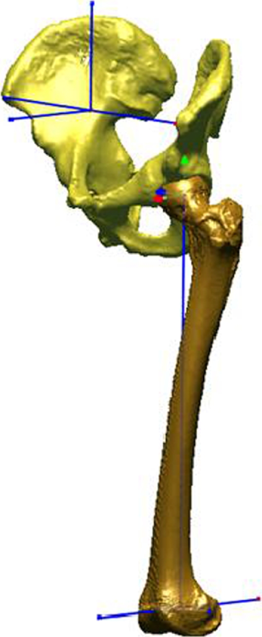
The neutral position, shown here in the anterolateral view, was established using anatomic axes for measurement purposes of the three rotations of the hip. These axes were defined by bony landmarks on the femur and pelvis.
CAD models of commonly used THA and SRA components were implanted virtually into each 3-D–modeled hip at the conclusion of intact cadaveric testing. The resurfacing system used a 3-mm thick femoral head and 170°-acetabular cup of equal 3-mm thickness. The cup, placed in 45° inclination, was matched to the anteversion of each acetabulum (average, 23° ± 4°). The intact head center served as a guide for placement of the component head to avoid impingement. If necessary, we used a larger head size to avoid notching of the femoral neck. The acetabulum of each model was virtually retroverted 10° and each cup reimplanted to match the new version of the acetabulum to the created retroverted case of each model. In 45° inclination and with the anteversion matched to each acetabulum, we virtually implanted a hemispheric cup in each pelvis for THA. A CAD model of a common canal-filling stem with a 132° neck-shaft angle, a 32-mm head, and 12-mm neck diameter was used on the femoral side. The head center and anteversion of the stem were aligned congruently with each intact femur. Each stem was virtually anteverted by 10° to create anteverted prostheses.
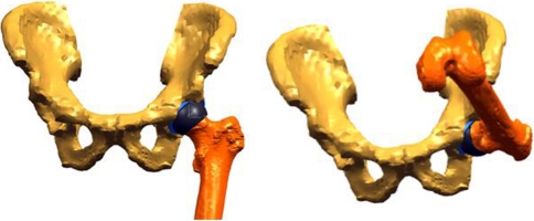
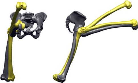
The same 12 maneuvers completed during intact cadaveric testing then were simulated using the computer-based replicas of each specimen implanted with CAD models of the resurfacing and hip replacement components. We used a custom collision-detection routine to detect bony or prosthetic impingement to determine the ROM to impingement after THA and SRA (Figs. 3, 4). The ROM of each implanted hip during each maneuver was compared with values recorded from the same specimen in the intact condition. This allowed us to determine whether each reconstruction could restore the full functional motion of the hip in each position or whether motion deficits were present resulting from impingement (Appendix 1).
Fig. 3.
A ROM simulation is shown. The femur of one typical specimen is first placed in the neutral position after hip resurfacing and then undergoes maximum flexion. (From ORS Transaction #0276: Doherty SD, Thompson MT, Usrey MM, Murihead-Allwood S, Noble PC. Does hip resurfacing restore normal range of motion and provide better joint motion than THR? Trans Orthop Res Soc. 2007;32:paper 0276.)
Fig. 4.
Various positions of the femur recreated in the anterior and lateral views are shown. The maneuvers in yellow represent the motion during resurfacing, which, on average, exhibited nearly 25% less motion compared with the intact specimens.
For ease of comparison and to focus on the most clinically relevant maneuvers, the 12 positions were narrowed down to six for presentation. These consist of three functional maneuvers generating anterior impingement (internal rotation in neutral flexion/extension and in 90° flexion; maximum flexion in neutral rotation and adduction) and three maneuvers generating posterior impingement (external rotation in neutral F/E and in 90° flexion; hyperextension in neutral rotation and adduction) (Table 1). Paired t-tests at each maneuver were performed between SRA and THA ROM in the retroverted acetabulum to answer the first research question (Microsoft Excel 2007, Microsoft Corp, Redmond, WA, USA). Paired t-tests at each maneuver also were performed between a standard THA with a retroverted acetabulum and an anteverted stem with a retroverted acetabulum to examine the effect of increased anteversion (Microsoft Excel 2007).
Results
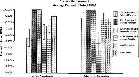
SRA resulted in ROM deficiencies in four of the six maneuvers, averaging 25% to 29% in the normal and retroverted acetabular positions (Fig. 5). In contrast to SRA, THA in the retroverted acetabulum resulted in deficiencies in ROM in only two of the six maneuvers. The two deficient positions averaged 5% deficiency (p < 0.05).
Fig. 5.
When compared with the intact specimens, ROM was restored in only two of the six maneuvers after SRA for the normal and retroverted acetabula with an average of 25% to 29% deficiency for the other four maneuvers.
Comparing normal THA and retroverted THA with increased femoral stem anteversion, the differences were less dramatic. THA allowed normal ROM in all six positions in the normal acetabulum and in four of the six retroverted acetabula. Increasing femoral stem anteversion restored ROM in five positions and showed only a 2% deficiency in the sixth position (Fig. 6) with acetabular retroversion.
Fig. 6.
Compared with the intact specimens, ROM was fully restored using THA in all six maneuvers in the normal acetabulum, but only four of the six maneuvers were in retroverted acetabula.
Discussion
Recent advancements in hip arthroplasty have focused attention on hip ROM and impingement [8–11, 15]. Also, acetabular retroversion is increasingly recognized to be associated with hip disorders and arthrosis [1, 2, 4, 6, 12, 13]. Although prosthetic component positioning is not determined solely by native acetabular anatomy, acetabular retroversion can create a problem if the surgeon implants the device in the anatomic position. We therefore asked: (1) Is there a difference in ROM between SRA and THA in the retroverted acetabulum; (2) Does increased femoral anteversion improve ROM in the retroverted acetabulum?
By its nature, this study has several limitations. First, it is a cadaveric study. Generally, hip ROM studies involve either cadaveric testing or virtual simulations. Often, cadaveric testing eliminates soft tissue structures which may define the limit of natural hip ROM (soft tissue restraints). Computer simulation models tend to overestimate hip ROM based on the collision of only bony structures. By combining cadaveric measurements with intact soft tissues and computer simulation to ideally place arthroplasty components, we have tried to overcome the limits of these studies by describing natural hip motion in a reproducible fashion and examining postoperative ROM in the natural hip ROM. Furthermore, we believe direct measurement of hip ROM in this study is superior to clinical testing by physical examination of patients’ hip motion after arthroplasty, which introduces biases including patient discomfort, examiner effort, and adjacent spinal motion [15]. Second, we arbitrarily selected 10° acetabular retroversion in our model. From a practical point of view, locating cadaveric specimens that had acetabular retroversion is not possible. Additionally, we are not aware of a reliable quantitative evaluation of acetabular retroversion. For example, in a detailed analysis of acetabular retroversion in 96 hips with developmental dysplasia, Jamali et al. could not easily quantify the degree of acetabular version, but instead relied on the presence of the crossover sign [8]. Third, we selected the acetabular component position based on the anterior and posterior walls of the acetabulum (or the transverse acetabular ligament) to guide acetabular component placement. We selected this position to maximize the ROM potential of the arthroplasty. A recent study showed that any acetabular component uncovered anteriorly or posterior uncoverage greater than 5 mm leads to substantial impingement and decreased ROM [10]. In the clinical setting, 15° to 20° acetabular anteversion is preferred by many surgeons to minimize prosthetic posterior hip dislocation. When acetabular retroversion is present, to achieve this amount of desired anteversion, the acetabular component will need to have much more than 5 mm of posterior uncoverage. Posterior impingement or poor component stability will likely result in this situation [7].
Retroversion of the acetabulum is increasingly recognized to be associated with mechanical abnormalities of the hip [12]. Troelsen et al. suggested reduced acetabular anteversion was a risk factor for a poor result from periacetabular osteotomy and attributed this to the difficulty in achieving proper acetabular reorientation [14]. With hip arthroplasty components, it is understandable that the ideal position for the acetabular component also would be difficult to define given this anatomic variant. Furthermore, it may be important to optimally define and achieve acetabular positioning in cases of abnormal anatomy. Optimal acetabular positioning may be even more important in metal-on-metal prosthetic designs, including SRA. De Haan et al. reported that with metal-on-metal hip resurfacing, an arc of cover less than 10 mm was correlated with a greater risk of a higher concentration of serum metal ions, which most likely is the result of edge loading [3]. Our data show that limited hip motion will result with both procedures in the presence of acetabular retroversion.
Based on our data, we believe that hip arthroplasty impingement can be avoided even in the presence of 10° acetabular retroversion by a compensatory increase of an additional 10° femoral anteversion without any acetabular component uncoverage posteriorly. If more acetabular component anteversion is desired, then some posterior uncoverage or anterior acetabular bone removal may be considered. SRA offers very limited ability to change the anteversion of the femoral component. THA, however, especially with modular components, readily allows increased anteversion which we propose will be useful in the case of acetabular retroversion.
Acknowledgments
We acknowledge and thank Sabir K. Ismaily BS, for his contributions to the manuscript.
Appendix 1
Steps involved in virtual cup implantation and simulated acetabular retroversion
The intact acetabulum is reconstructed into a 3-D model from DICOM CT images and is oriented in an anatomic position based on anterior-superior iliac spine points and points at the pubic symphysis (Fig. 1).
For normal acetabula, a cup then is virtually implanted in the acetabulum in 45° inclination and matched to the anteversion of the acetabulum based on a plane fit through rim points (Fig. 2).
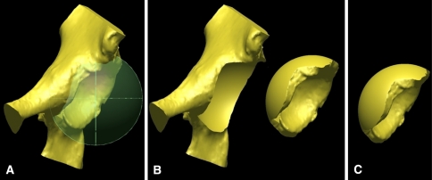
After implantation and ROM simulation with the normal acetabulum, each acetabulum is retroverted 10° through a process in which a sphere large enough to enclose any impinging portion of the rim (5 mm greater in diameter than the implanted cup) is centered in the acetabulum (Fig. 3A). The acetabulum only in this sphere (Fig. 3B) then is retroverted 10o, resulting in a retroverted acetabulum (Fig. 3C). The rest of the pelvis remains in its initial position.
The cup then is reimplanted, matching the version of the retroverted acetabulum (Fig. 4). Finally, ROM is repeated for the implanted, retroverted acetabulum.
Fig. 1.
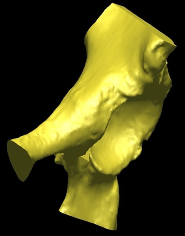
An intact reconstructed acetabulum in its anatomic initial position is shown.
Fig. 2.
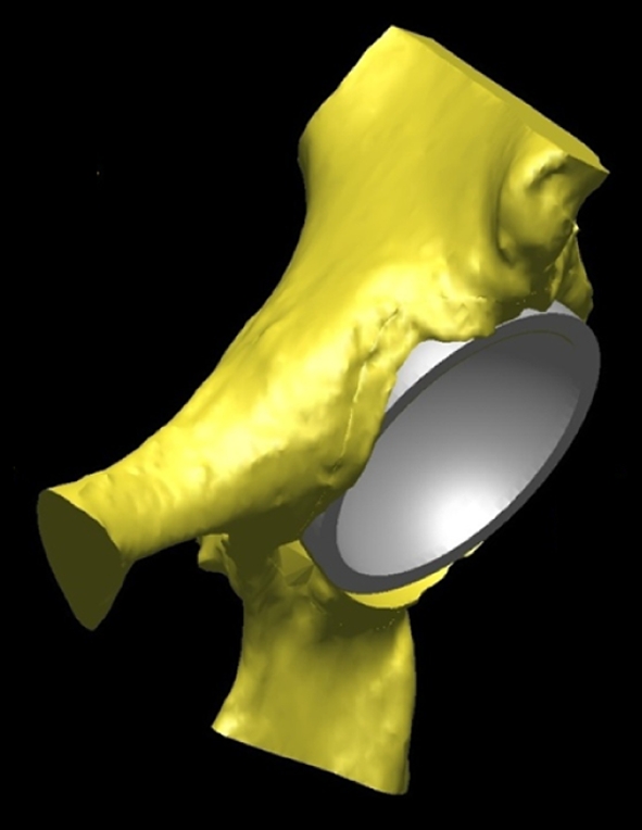
The virtually implanted resurfacing cup in the normal acetabulum (45o inclination, matched anteversion) is shown.
Fig 3A–C.
(A) A large sphere encompassing any impinging portion of the rim is centered in the acetabulum. (B) The portion of the acetabulum in this sphere is disconnected from the rest of the pelvis so that only the acetabulum can be rotated. The two pieces are shown separated here for emphasis, but the acetabulum is actually still centered at the same spot of the pelvis. (C) The acetabulum then is retroverted 10°, shown here separated from the pelvis for emphasis and comparison with Illustration B.
Fig. 4.
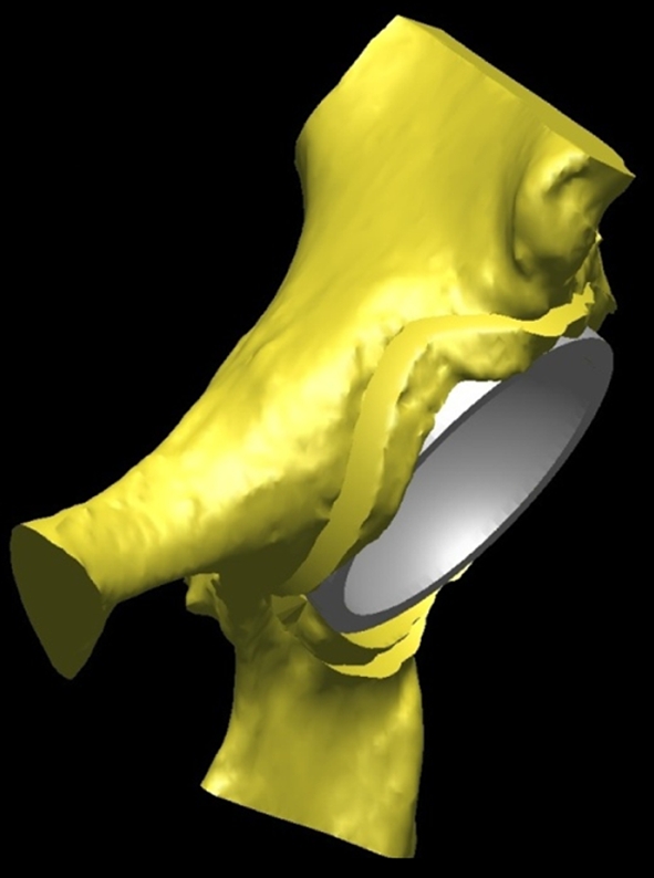
The virtually implanted resurfacing cup in the retroverted acetabulum (45° inclination with version matched to the retroverted acetabulum) is shown.
Footnotes
Each author certifies that he or she has no commercial associations (eg, consultancies, stock ownership, equity interest, patent/licensing arrangements, etc) that might pose a conflict of interest in connection with the submitted article.
Each author certifies that his or her institution approved the human protocol for this investigation, that all investigations were conducted in conformity with ethical principles of research, and that our board of ethics does not require informed consent for participation in such a study.
This work was performed at The Methodist Hospital, Houston, TX, USA.
References
- 1.Beaule PE, O’Neill M, Rakhra K. Acetabular labral tears. J Bone Joint Surg Am. 2009;91:701–710. doi: 10.2106/JBJS.H.00802. [DOI] [PubMed] [Google Scholar]
- 2.Burnett RS, Della Rocca GJ, Prather H, Curry M, Maloney WJ, Clohisy JC. Clinical presentation of patients with tears of the acetabular labrum. J Bone Joint Surg Am. 2006;88:1448–1457. doi: 10.2106/JBJS.D.02806. [DOI] [PubMed] [Google Scholar]
- 3.Haan R, Pattyn C, Gill HS, Murray DW, Campbell PA, Smet K. Correlation between inclination of the acetabular component and metal ion levels in metal-on-metal hip resurfacing replacement. J Bone Joint Surg Br. 2008;90:1291–1297. doi: 10.1302/0301-620X.90B10.20533. [DOI] [PubMed] [Google Scholar]
- 4.Ganz R, Parvizi J, Beck M, Leunig M, Notzli H, Siebenrock KA. Femoroacetabular impingement: a cause for osteoarthritis of the hip. Clin Orthop Relat Res. 2003;417:112–120. doi: 10.1097/01.blo.0000096804.78689.c2. [DOI] [PubMed] [Google Scholar]
- 5.Incavo SJ, Thompson MT, Gold JE, Patel RV, Icenogle KD, Noble PC. Which procedure better restores intact hip range of motion: total hip arthroplasty or resurfacing? A combined cadaveric and computer simulation study. J Arthroplasty. 2010 Apr 7. [Epub ahead of print]. [DOI] [PubMed]
- 6.Jamali AA, Mladenov K, Meyer DC, Martinez A, Beck M, Ganz R, Leunig M. Anteroposterior pelvic radiographs to assess acetabular retroversion: high validity of the “cross-over-sign”. J Orthop Res. 2007;25:758–765. doi: 10.1002/jor.20380. [DOI] [PubMed] [Google Scholar]
- 7.Jolles BM, Zangger P, Leyvraz PF. Factors predisposing to dislocation after primary total hip arthroplasty: a multivariate analysis. J Arthroplasty. 2002;17:282–288. doi: 10.1054/arth.2002.30286. [DOI] [PubMed] [Google Scholar]
- 8.Kluess D, Zietz C, Lindner T, Mittelmeier W, Schmitz KP, Bader R. Limited range of motion of hip resurfacing arthroplasty due to unfavorable ratio of prosthetic head size and femoral neck diameter. Acta Orthop. 2008;79:748–754. doi: 10.1080/17453670810016803. [DOI] [PubMed] [Google Scholar]
- 9.Mont MA, Schmalzried TP. Modern metal-on-metal hip resurfacing: important observations from the first ten years. J Bone Joint Surg Am. 2008;90(suppl 3):3–11. doi: 10.2106/JBJS.H.00750. [DOI] [PubMed] [Google Scholar]
- 10.Patel AB, Wagle RR, Usrey MM, Thompson MT, Incavo S, Noble P. Guidelines for implant placement to minimize impingement during activities of daily living after total hip arthroplasty. J Arthroplasty. 2009 Dec 17. [Epub ahead of print]. [DOI] [PubMed]
- 11.Schmalzried TP, Silva M, la Rosa MA, Choi ES, Fowble VA. Optimizing patient selection and outcomes with total hip resurfacing. Clin Orthop Relat Res. 2005;441:200–204. doi: 10.1097/01.blo.0000192354.76792.bb. [DOI] [PubMed] [Google Scholar]
- 12.Siebenrock KA, Schoeniger R, Ganz R. Anterior femoro-acetabular impingement due to acetabular retroversion: treatment with periacetabular osteotomy. J Bone Joint Surg Am. 2003;85:278–286. doi: 10.2106/00004623-200302000-00015. [DOI] [PubMed] [Google Scholar]
- 13.Tonnis D, Heinecke A. Acetabular and femoral anteversion: relationship with osteoarthritis of the hip. J Bone Joint Surg Am. 1999;81:1747–1770. doi: 10.2106/00004623-199912000-00014. [DOI] [PubMed] [Google Scholar]
- 14.Troelsen A, Elmengaard B, Soballe K. Medium-term outcome of periacetabular osteotomy and predictors of conversion to total hip replacement. J Bone Joint Surg Am. 2009;91:2169–2179. doi: 10.2106/JBJS.H.00994. [DOI] [PubMed] [Google Scholar]
- 15.Vail TP, Mina CA, Yergler JD, Pietrobon R. Metal-on-metal hip resurfacing compares favorably with THA at 2 years followup. Clin Orthop Relat Res. 2006;453:123–131. doi: 10.1097/01.blo.0000238852.08497.92. [DOI] [PubMed] [Google Scholar]


