

Abstract
Electromechanical reshaping (EMR) has been recently described as an alternative method for reshaping facial cartilage without the need for incisions or sutures. This study focuses on determining the short- and long-term viability of chondrocytes following EMR in cartilage grafts maintained in tissue culture. Flat rabbit nasal septal cartilage specimens were bent into semi-cylindrical shapes by an aluminum jig while a constant electric voltage was applied across the concave and convex surfaces. After EMR, specimens were maintained in culture media for 64 days. Over this time period, specimens were serially biopsied and then stained with a fluorescent live–dead assay system and imaged using laser scanning confocal microscopy. In addition, the fraction of viable chondrocytes was measured, correlated with voltage, voltage application time, electric field configuration, and examined serially. The fraction of viable chondrocytes decreased with voltage and application time. High local electric field intensity and proximity to the positive electrode also focally reduced chondrocyte viability. The density of viable chondrocytes decreased over time and reached a steady state after 2–4 weeks. Viable cells were concentrated within the central region of the specimen. Approximately 20% of original chondrocytes remained viable after reshaping with optimal voltage and application time parameters and compared favorably with conventional surgical shape change techniques such as morselization.
Keywords: Cartilage reshaping, Chondrocytes, Tissue viability, Electrochemistry
Introduction
Electromechanical reshaping (EMR) of cartilage7 is a new technique that can be used to reshape cartilage tissue without the need for incisions, suturing, scoring, or morselization.3,12 EMR has been developed as an alternative to thermally assisted cartilage reshaping—a method utilizing laser8,19,28 or radio frequency9 induced heating to reshape or thermoform facial cartilage tissue. In EMR, cartilage is placed between two conductive surfaces that (a) mechanically deform cartilage into a desired shape and (b) serve as electrodes to create a DC electric field within the tissue.7,21 Recently, we demonstrated that EMR can reshape flat, rectangular porcine, or rabbit nasal septal grafts into stable semi-cylindrical geometries, with, the degree of the shape change being dependent on applied voltage and application time.21 Unlike thermal reshaping methods, EMR did not produce any significant temperature rises in the tissue, suggesting an electro-chemical mechanism for the process, rather than just simply resistive heating.7,21 Additional evidence supporting the electrochemical nature of this process is that shape change is strongly correlated with total electric charge transferred in the EMR circuit during voltage application time.21
Cartilage is a charged polymer hydrogel composed of a collagen and a proteoglycan matrix filled with an aqueous solution of Na+, K+, Cl−, and other ions. Mechanical contact between the metal electrode and the wet cartilage specimen initiates a number of oxidation–reduction reactions at the metal–tissue interface.2,5 Application of external voltage to these electrodes may change the intensity or reverse direction of these chemical reactions, depending on voltage strength and polarity.1,29 Regardless of what precise role electrochemical reactions play in producing shape change during EMR, the reactions themselves and their by-products alter the chemical composition of the tissue, possibly creating tissue damage. In other biomedical applications, electrically driven chemical reactions have been suggested as a low-cost means of cancer treatment for large, solid tumors, in which the toxic by-products of electrochemical reactions around the cathode alter the pH of the tissue, leading to necrosis.15–18,29,30 Similar oxidation–reduction reactions may occur at the electrode–tissue interface during EMR.
We expect that increase in applied voltage and application time will decrease cartilage viability due to increase in production and accumulation of the toxic byproducts of electrochemical reactions. Total chemical injury sustained by cartilage after EMR might not be detected immediately following the treatment as some chondrocytes damaged beyond repair die trough apoptosis. We also expect that the most intensive injury to cartilage will be in the vicinity of electrodes, where intensity of electrochemical reactions is high. In this study, we determine long-term cartilage viability after EMR as a function of applied voltage, application time, and electric field configuration. It was our objective to determine the spatial distribution of viable chondrocytes in cartilage grafts subjected to EMR at various settings both immediately and after preservation in tissue culture for 64 days. Characterization of cartilage viability in ex vivo specimens after EMR is an important first step in determining the potential long-term response of electrically treated cartilage and is critical in the development of EMR as a viable treatment modality for reconstructive and esthetic facial surgery.
Materials and Methods
Tissue Harvest
Nasal septal cartilage was harvested from the crania of freshly euthanized New Zealand white rabbits (2–2.5 kg) using a previously described method34 in accordance with the Institutional Animal Care and Use Committee (IACUC) regulations at the University of California, Irvine. A rectangular slab (15.2 ± 0.2 × 5.1 ± 0.1 × 1.1 ± 0.1 mm3) was dissected using a razor from the central region of each septum perpendicular to the caudal–cephalic axis and meticulously dissected free of perichondrium.
Electromechanical Reshaping
Immediately after dissection, cartilage specimens were placed between the two semi-cylindrical aluminum electrodes of the electroforming jig (Fig. 1a).7,21 The convex and concave electrodes were connected to the positive and negative terminals of a DC power supply (Model PPS-2322, Amrel, Arcadia, CA, USA), respectively, which supplied a constant electrical voltage. Voltage and application time combinations were 3, 4, 5, and 6 V and 1, 2, and 3 min, respectively. Over this range of voltages and application times shape change varies from being just detectable at “low” EMR parameters (i.e., 3 V and 1 min) to significant where the specimen shape conforms exactly to that of the jig (at 5 V, 2 min and 6 V, 1 min).21 Two control groups were used for this study. First control group consisted of four specimens evaluated immediately for viability. In the second control group specimens were placed in the jig for 1, 2, and 3 min without voltage application. Four specimens were used for each time interval for a total of 12 specimens. In the treatment group two, three or four samples were electroformed at each voltage–time combination for a total of 42 specimens. Four specimens per parameter set were used in most sets except for 3 min and 4, 5, and 6 V were used for 3, 2, and 2 specimens, respectively. Two variants of standard EMR were performed to investigate specific issues related to electric field configuration on cell viability: (1) to study the effect of the electrode polarity on chondrocyte viability, the polarity of the electrodes was reversed; (2) to study the effect of electric field configuration, the central section of cartilage specimen was insulated from the convex electrode by the insertion of a rectangular piece (5 × 5 × 0.1 mm3) of Teflon insulating tape. These experiments used an electroforming voltage of 5 V applied for 2 min. Previous studies identified this combination of voltage and time as producing maximum shape with the current jig and setup.21
FIGURE 1.

Experimental procedure to determine viability of chondrocytes after electroforming. A rectangular cartilage specimen is excised from a rabbit septum and placed into the electroforming jig (a). After EMR, cartilage specimen is removed from the jig (specimens reshaped at 5 V for 2 min (i) and 0 V for 2 min (ii) are shown) and thin (>200 μm) section of tissue is dissected from it (b). The thin section is stained with a “live–dead assay” and then imaged using a confocal fluorescent microscope (c). The bulk of the specimen is returned to cell culture (d). After 48–72 h, the specimen is again removed from the culture, and another thin section is excised (e), stained, and imaged for viable cells (f). The process is repeated, and the specimen is returned to culture (g)
Confocal Imaging and Viability Analysis
After EMR, cartilage specimens were examined for chondrocyte viability using the Live/Dead viability assay for mammalian cells (Molecular Probes, Eugene, OR, USA), combined with confocal microscopy.6,11,13,23–25,31,35 Following removal from electroforming jig, specimens were stored in 0.9% 0.154 M saline solution at a room temperature of +21 °C for no longer than 1 h. Imaging was performed serially over a span of 64 days on each specimen by sectioning a thin specimen from the specimen and then imaging it (Figs. 1b–1d). Sectioning was performed on the same side. The remainder of the specimen was then returned to culture. At regular intervals the specimen was removed from culture, and another thin specimen at the edge was sectioned off and imaged using confocal microscopy (Figs. 1e–1g). Each serial section was extremely thin, and the bulk of the reshaped graft was returned to culture after each imaging sequence.
A thin rectangular cross section of cartilage (approximately 200 ± 50-μm thick, measured with digital micrometer) was meticulously excised from the specimen as shown in Fig. 1b using microdissection techniques and scalpels. The section was placed in a Live/Dead assay staining solution consisting of 4 mL of SYTO 10 and 2 mL of DEAD Red (Molecular Probes, Eugene, OR, USA) in 1 mL of Hank’s Buffered Saline Solution. The remaining section was returned to cell culture (see below).
Laser-scanning confocal microscope (Carl Zeiss MicroImaging GmbH, Jena, Germany) employing a 488-nm argon laser excitation source at 10× magnification and axial resolution better than 1 μm was used to image the section (Fig. 1c). Live and dead cells emitted green and red fluorescence signals, respectively. Ten to eleven frames spanning the entire section were collected during the imaging, stored on the computer system linked with the microscope in BMP file format, and subsequently assembled into digital montage using AdobePhotoshop (Adobe Systems Inc., San Jose, CA, USA) (Fig. 5). Live (green) cells in the image plane were identified. The green channel information was extracted from the image file and thresholded (Figs. 2a and 2b); live (green) cells were automatically counted using ImageJ (National Institute of Health) software. The number of live cells was manually counted on 10 randomly selected images and compared with the automated count. The correlation between the two counting methods was better than 98% (Fig. 2c). The area of the section was measured on digital montage and surface cell density (number of cells per unit area) was calculated.
FIGURE 5.
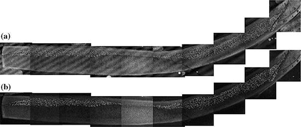
Digital montage of a thin section of a septal cartilage electroformed at 5 V for 2 min after 62 days in culture media showing distributions of (a) non-viable and (b) viable cells obtained using, respectively, red and green channels of confocal fluorescent microscope. Regular streak pattern on the red-channel image is due to interference of laser light in the cover glass. Positive and negative electrodes were at the concave and convex sides of the sample, respectively
FIGURE 2.

(a) Magnified image of cartilage section acquired from the green (live) channel of confocal microscope. Live cells are visible as bright round dots in the middle and right-hand side of grayscale image. (b) The same image thresholded for an automated cell count of green (live) cells. (c) Correlation between automated and manual count of green (live) cells
The remainder of the specimen was then washed three times (15 min each) in an antibiotic solution containing phosphate buffered saline with gentamicin (200 mg/L) and amphotericin B (22.4 mg/L) under sterile conditions, placed in tissue culture in Dulbecco’s Modified Eagle’s Media (Sigma, St. Louis, MO, USA) containing 10% fetal calf serum, gentamicin sulfate (Fisher Scientific, Pittsburgh, PA, USA), penicillin, streptomycin, and glutamine and incubated at 37 °C and 7.5% CO2 (Fig. 1d). The media were replaced daily. No specimens were lost due to contamination. The cartilage specimens were removed from the culture every 48 or 72 h and new thin, rectangular sections were dissected from them (Fig. 1e). Dissected sections were stained and then imaged with confocal microscope following procedure described above (Fig. 1f). After dissection, the remaining portion of the specimen was again washed in antibiotic solution, placed in culture media, and returned to the incubator (Fig. 1g). Controls were placed into the jig and held without application of electric voltage for 1, 2, and 3 min, then imaged using the same sequence as the electroformed specimens. All specimens were maintained in culture for total of 64 days. Well before this time a nearly steady-state concentration of viable chondrocytes was observed in most samples electroformed for 1 and 2 min.
The number of live (green) cells in the sample regions in contact with the anode and cathode was compared. A straightline dividing section approximately in half was drawn on each consecutive frame, and the number of live cells in each half was counted. Sections obtained from specimens immediately after removal from the jig and after 30 and 62 days in culture were studied.
Results
Cell viability vs. Applied Voltage and Application Time
The analysis of electroformed septal cartilage using confocal microscopy identified live and dead cells within samples. A representative distribution of live and dead cells in control specimen (group II, 2 min) obtained immediately after specimen was removed from the jig is shown in Fig. 3-(i). Sections dissected from the samples just after extraction from the crania (control group I) and following deformation in the jig (control group II) contained predominantly green fluorescent cells with a small number (<1%) of red cells evenly distributed throughout the section (Fig. 3-(i)). A region of predominantly red fluorescent cells surrounded the periphery of the sections in both electroformed and control samples (Fig. 2). In controls, these regions of red fluorescence were the narrowest (approximately 50 μm wide). Average density of the green cells in samples from both control groups was 470 ± 80 cells/mm2. No statistical difference in the green cell density in both control groups was detected.
FIGURE 3.

Distribution of (a) non-viable (red) and (b) viable (green) cells in septal cartilage observed using, respectively, red and green channels of confocal fluorescent microscope. Non-viable (red) and viable (green) cells are visible as bright round dots on the corresponding grayscale images: (i) control, (ii) immediately after electroforming at 5 V for 2 min, (iii) after electroforming at 5 V for 2 min with electric insulation tape (EIT) inserted between cartilage and electrode. Indicated position of positive and negative electrodes is the same on all images
In the electroformed samples a mixed population of green and red fluorescent cells was present. In all cartilage samples maintained in culture, the number of the green fluorescent cells decreased with time in cell culture. In the dying cells, the green fluorescent signal was first replaced with red. Then, after approximately 20 days, the red fluorescence disappeared, signifying loss of cell structural integrity. Figure 4 shows the green cell density (number of cells per unit area) in cartilage sections as a function of time in culture after 1, 2, and 3 min of EMR at 0, 3, 4, 5, and 6 V. Data were normalized relative to the average value (N = 4) of initial density of viable (green) cell in samples from control group II measured after EMR and prior to placement the sample in culture. Content of the green cells in cartilage samples from control group II is shown for comparison. The density of the green cells in control samples steadily declined to 350 ± 90 cells/mm2 after 64 days, indicating that the process of cell culture results, to some degree, in cell death for large septal explants.
FIGURE 4.

The normalized density (number of cells per unit area) of the green (viable) cells in cartilage after electroforming for (a) 1, (b) 2, and (c) 3 min as a function of time in culture. The content is shown as a percentage of the average number of viable cells observed in samples from control group II before placement in culture. Standard deviation is indicated
In the electroformed samples, the initial percentage of the viable cells was less than in controls and in general decreased with an increase in either voltage or application time. Although this trend was observed for average values of viable cell densities for all electroformed specimens during 62 days in culture or until viable cells were detected, statistical analysis with ANOVA revealed no significant difference between electroforming for 1 min at 3 and 4 V as well as 5 and 6 V. The number of viable cells detected in the samples exposed to 5 V for 2 min after 62 days in culture is approximately 20% of the value of control samples evaluated immediately after specimen harvest (Figs. 4 and 5). No viable cells were detected in any specimens electroformed for 3 min after 3 weeks in culture (Fig. 4c). As the time in tissue culture increased, fewer viable chondrocytes were identified at the peripheral sections of the specimen, and the extent of this peripheral region of non-viable cells increased with time. At the same time, viable cells were always located closer to the cathode (Fig. 5).
Effect of Electric Field Configuration on Cell Viability
The green signal intensity was greatest near the cathode (concave electrode) and decreased toward the anode (convex electrode) (Fig. 3b-(ii)). The red signal followed the reverse pattern: being greatest in proximity to the anode (Fig. 3a-(ii)). This pattern was independent of the choice of the concave or convex electrode as a cathode. Figure 6 demonstrates average percentage of live (green) cells in the specimen half adjacent to the cathode. Analysis of live cells number using ANOVA demonstrated no statistical difference between the two halves in samples from both control groups and between samples from control group II treated for 1, 2, and 3 min. In all electroformed samples the half closest to the cathode had the largest live cell content during all 62 days of the study. In the samples treated for 1 min, immediately after electroforming the relative content of live cells in the half located near the cathode was changing from 67 ± 8 to 79 ± 8% in samples treated using 3 and 6 V, respectively (Fig. 6a). The change in the live cell content in the opposite half located near the anode was from 30 ± 8 to 23 ± 8% in samples treated using 3 and 6 V, respectively (Fig. 6c). In the samples treated for 2 min, immediately after electroforming the relative content of live cells in the half located near the cathode was changing from 72 ± 8 to 100% in samples treated using 3 and 6 V, respectively (Fig. 6b). Similarly, the change in the live cell content in the opposite half located near the anode was from 24 ± 6 to 0% (Fig. 6d). The relative content of live cells increased with time in culture in all samples. After 62 days in culture, it was in the range from 90 ± 10 to 100% in all aforementioned samples. In all samples treated for 3 min 100% of live cells were located in the half near the cathode.
FIGURE 6.
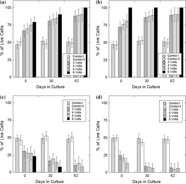
Average percentage of live (green) cells in the half of the sample closest to the cathode after treatment for 1 (a) and 2 min (b) and anode after treatment for 1 (c) and 2 min (d). Standard deviation is indicated
In all specimens electroformed without the insertion of an insulator between the tissue and the electrode surface, the longitudinal distribution of the both live and dead cells was relatively uniform (Fig. 3-(ii)). Introduction of the thin insulator produced a region containing predominantly green fluorescent cells immediately adjacent to the insulator with a clear demarcation between predominately live and mixed live–dead cell populations. This green cell zone is as wide as the insulation and extends from the sample–insulator interface to approximately half the thickness of the sample, the same thickness as observed without the insulator (Fig. 3-(iii)).
Discussion
EMR is a potentially transformative surgical technique because it achieves shape change without the use of sutures or scalpels and exploits the intrinsic properties of cartilage as a charged polymer hydrogel. Our previous work has demonstrated the dependence of EMR on total charge transfer and suggests that the basis for this effect is in situ redox chemistry. The next most important issue that needs to be resolved is whether tissue viability can be maintained after EMR. The present studies investigated the effects of electro-mechanical reshaping on the viability of rabbit nasal septal cartilage and represent the next step needed to move this technology toward potential clinical implementation. During cartilage EMR, the applied electric field initiates and drives electrochemical reactions at the electrodes. The by-products of these reactions may have toxic effects on cartilage chondrocytes. Cartilage cells within the entire tissue volume may be affected by the reaction products, which are free to move down electrical potential and concentration gradients away from the immediate vicinity of the electrode–tissue interface.
Even without the application of current, the ions in the extracellular fluid and metal electrodes can initiate redox reactions immediately upon contact. However, without application of external voltage, the intensity of these reactions is insufficient to create any measurable damage to the cells (Fig. 3a-(i)). The thin peripheral layer of dead cells identified in control cartilage samples (Fig. 3a-(i)) was also observed previously in native cartilage samples11 and may occur as a consequence of subtle mechanical injury to the tissue during removal of the adherent perichondrium. The application of voltage results in more intense chemical reactions and consequently destruction of chondrocytes begins with the cells located closest to the electrodes. At the anode, formation of hydrogen ions from hydrolysis and aluminum oxidation,2,20 combined with formation of molecular chlorine, results in pH drop, harming tissues.16–18 At the cathode, production of hydroxyl ions results in a pH increase and at appropriate concentrations, also produces tissue damage.16–18 We have found that the most intense cellular injury occurs near the anode (Figs. 3-(ii), 5, and 6), regardless of whether it served as a concave or convex electrode. This observation is consistent with the use of anodic current for destruction of malignant tissues as described in previous cancer applications of in situ redox chemistry5,10,29; however, the use of electrochemically active aluminum for the electrodes might needlessly increase these toxic effects. In this study we have used aluminum sheet as electrode material as it can be easily formed into semi-cylindrical shape, consistent with the geometry used in our previous study of cartilage reshaping.7,9,11,21 However, in future investigations, we are evaluating the use of platinum and graphite electrodes as suitable electrode materials for EMR, as they do not generate reactive species. Likewise, this study is focused on the use of platinum needles as electrodes, as they can be used to spatially limit the extent of tissue injury. Needle-based systems for EMR can be embodied into minimally invasive percutaneous and transmucosal procedures and devices.
Diffusion of hydrogen and hydroxyl ions from the electrodes is partially countered by the intrinsic buffering capacity of the extracellular matrix and fluid.16–18 Chondrocytes farther away from the electrodes are exposed to lower concentrations of these species and do not sustain acute injury as evidenced by the spatial distribution of viable cells immediately following EMR (Fig. 3-(ii) and (iii)) Rather, the changes in the surrounding extracellular milieu may trigger apoptosis or may even have no effect at all. Continued chondrocyte death occurred most rapidly during the first 3 weeks in culture (Fig. 4). This rate slowed significantly after 3 weeks and reached a rate comparable with those observed in controls. This suggests that the remaining chondrocytes are either completely recovered from the toxic effects, or remain unaffected. Viable chondrocytes are concentrated in the central portion of the specimen about 0.2–0.5 mm away from the electrodes (Fig. 5). Thus, viable and non-viable cells can be spatially separated from one another in electroformed cartilage. Also, chondrocytes can be selectively preserved by insulating the cartilage surface (Fig. 3-iii). In such a configuration, the electric field decreases rapidly outside the insulated zone, limiting production and spread of toxic electrochemical products.
Previously, we demonstrated that in the electroformed specimens the shape retention increases with increase in electroforming voltage and time.7,21 Specimens exposed to 5 V for 2 min retain about 80% of the jig’s curvature,21 and here we have determined that under the same conditions, approximately 20% of initial chondrocyte populations remains viable (Figs. 4 and 5). A value of 20% for viable cells observed in these specimens exceeds the figure of 10% viable chondrocytes reported for morselized human nasal cartilage.4 Morselization is a common technique used to shape cartilage grafts for facial operations through the crushing of tissue. Conventional procedures to shape cartilage involve morselization, carving, and excising cartilage tissue which are intrinsically destructive processes, or suture placement which are used to counter the forces in cartilage that resist deformation. Bujia4 evaluated the viability of cartilage within several hours after the morselization. In contrast, the viability of electroformed cartilage exceeded 50% for all voltages at 1 and 2 min 48 h after EMR. Hence, cultured morselized cartilage would likely show even lower viability counts after this time interval elapsed. Note that a reduction in the viable chondrocyte population by 20% was also observed in control samples (Fig. 4). This maybe a consequence of the tissue culture process or from mechanical trauma related to extraction from the crania. Since these factors will be absent during in vivo EMR procedures, it may likely that an additional 20% of cells will remain viable, particularly in a native, vascularized tissue bed surrounded by a stem cell-rich perichondrium. Cell culture/ex vivo methods thus likely overestimate tissue injury.
The identification of viable chondrocytes regions in reshaped specimens combined with the establishment of clinically relevant shape change demonstrates that EMR can be performed in a spatially selective way, similar to the method used in the laser cartilage reshaping of the nasal septum19 and the ear.14,28 In laser cartilage reshaping, heating is generated at selected sites across the surface of mechanical deformed specimens, minimizing spatial extent of thermal injury, while at the same time creating sufficient thermally induced stress relaxation to preserve shape change.26,27,32,33 In general, mechanical deformation of a cartilaginous structure into a desired shape creates a complex non-uniform internal stress field with distinct regions of stress concentration.22 EMR can be limited to these zones using either surface or needle electrodes positioned at the locations of stress concentration. Diffusion of toxic reaction products into cartilage and subsequent cell damage can be controlled by the choice of electrode composition and geometry, applied voltage, and time, and potential rehydration with either saline or a suitable buffer solution. The chondrocytes surviving beyond the region of tissue injury may be able to repopulate the collagen matrix at least partially and maintain overall structural integrity, at least to the same degree observed in conventional surgical techniques.
Conclusion
The present results represent an important step in the potential development of cartilage EMR. We have demonstrated that though electroforming results in cell injury, a prudent selection of voltage and application time producing clinically relevant shape change and selectively preserving cells can be identified. Limiting application of electric voltage to specific regions of stress concentrations can also spatially localize cell injury. In light of these results, electroforming likely has a therapeutic potential primarily due to the creation of spatially selective changes in tissue mechanical properties at the expense of tissue injury in the same site. Therefore, the future goal of electro-mechanical reshaping may rely on the strategic targeting of electrical energy to regions of concentrated stress to elicit the greatest shape change and the development of methods to limit collateral electrochemical toxicity.
Open Access
This article is distributed under the terms of the Creative Commons Attribution Noncommercial License which permits any noncommercial use, distribution, and reproduction in any medium, provided the original author(s) and source are credited.
References
- 1.Bard AJ, Faulkner LR. Electrochemical Methods: Fundamentals and Applications. New York: Wiley; 2001. [Google Scholar]
- 2.Berendson, J., and D. Simonsson, Electrochemical aspects of treatment of tissue with direct current. Eur. J. Surg. Supp. 574:111–115, 1994. [PubMed]
- 3.Brent B. Technical advances in ear reconstruction with autogenous rib cartilage grafts: personal experience with 1200 cases. Plast. Reconstruct. Surg. 1999;104:319–334. doi: 10.1097/00006534-199908000-00001. [DOI] [PubMed] [Google Scholar]
- 4.Bujia J. Determination of the viability of crushed cartilage grafts: clinical implications for wound healing in nasal surgery. Ann. Plast. Surg. 1994;32(3):261–265. doi: 10.1097/00000637-199403000-00006. [DOI] [PubMed] [Google Scholar]
- 5.Colombo L, et al. Ion transport in tumors under electrochemical treatment: in vivo, in vitro and in silico modeling. Bioelectrochemistry. 2007;71(2):223–232. doi: 10.1016/j.bioelechem.2007.07.001. [DOI] [PubMed] [Google Scholar]
- 6.Diaz SH, Nelson JS, Wong BJF. Rate process analysis of thermal damage in cartilage. Phys. Med. Biol. 2003;48:19–29. doi: 10.1088/0031-9155/48/1/302. [DOI] [PubMed] [Google Scholar]
- 7.Ho KH, et al. Electromechanical reshaping of septal cartilage. Laryngoscope. 2003;113:1916–1921. doi: 10.1097/00005537-200311000-00011. [DOI] [PubMed] [Google Scholar]
- 8.Karamzadeh AM, et al. Long-term in vivo stability of rabbit nasal septal cartilage following laser cartilage reshaping: a pilot investigation. Lasers Surg. Med. 2005;36(2):147–154. doi: 10.1002/lsm.20123. [DOI] [PubMed] [Google Scholar]
- 9.Keefe M, et al. Radiofrequency cartilage reshaping: efficacy, biophysical measurements, and tissue viability. Arch. Facial Plast. Surg. 2003;5:46–52. doi: 10.1001/archfaci.5.1.46. [DOI] [PubMed] [Google Scholar]
- 10.Li K, et al. Effects of direct current on dog liver: possible mechanisms for tumor electrochemical treatment. Bioelectromagnetics. 1997;18(1):2–7. doi: 10.1002/(SICI)1521-186X(1997)18:1<2::AID-BEM2>3.0.CO;2-6. [DOI] [PubMed] [Google Scholar]
- 11.Li C, et al. Analysis of Nd:YAG laser-mediated thermal damage in rabbit nasal septal cartilage. Lasers Surg. Med. 2007;39(5):451–457. doi: 10.1002/lsm.20514. [DOI] [PubMed] [Google Scholar]
- 12.Lovice DB, Mingrone MD, Toriumi DM. Grafts and implants in rhinoplasty and nasal reconstruction. Otolaryngol. Clin. North Am. 1999;32:113–141. doi: 10.1016/S0030-6665(05)70118-3. [DOI] [PubMed] [Google Scholar]
- 13.Mainil-Varlet P, et al. Quantification of laser-induced cartilage injury by confocal microscopy in an ex vivo model. J. Bone Joint Surg. Am. 2001;83:566–571. doi: 10.2106/00004623-200104000-00012. [DOI] [PubMed] [Google Scholar]
- 14.Mordon S, et al. Laser cartilage reshaping in an in vivo rabbit model using a 1.54 micron Er:Glass laser. Lasers Surg. Med. 2004;34:315–322. doi: 10.1002/lsm.20029. [DOI] [PubMed] [Google Scholar]
- 15.Nillson E, Berendson J, Fontes E. Development of a dosage method for electrochemical treatment of tumours: a simplified mathematical model. Bioelectrochem. Bioenerg. 1998;47:11–18. doi: 10.1016/S0302-4598(98)00157-3. [DOI] [Google Scholar]
- 16.Nilsson E, Berendson J, Fontes E. Electrochemical treatment of tumours: a simplified mathematical model. J. Electroanal. Chem. 1999;460:88–99. doi: 10.1016/S0022-0728(98)00352-0. [DOI] [Google Scholar]
- 17.Nilsson E, Fontes E. Mathematical modelling of physicochemical reactions and transport processes occurring around a platinum cathode during the electrochemical treatment of tumours. Bioelectrochemistry. 2001;53:213–224. doi: 10.1016/S0302-4598(01)00097-6. [DOI] [PubMed] [Google Scholar]
- 18.Nilsson E, et al. Electrochemical treatment of tumours. Bioelectrochemistry. 2000;51(1):1–11. doi: 10.1016/S0302-4598(99)00073-2. [DOI] [PubMed] [Google Scholar]
- 19.Ovchinikov Y, et al. Laser septochondrocorrection. Arch. Facial Plast. Surg. 2002;4:180–185. doi: 10.1001/archfaci.4.3.180. [DOI] [PubMed] [Google Scholar]
- 20.Picard T, et al. Cathodic dissolution in the electrocoagulation process using aluminium electrodes. J. Environ. Monit. 2000;2(1):77–80. doi: 10.1039/a908248d. [DOI] [PubMed] [Google Scholar]
- 21.Protsenko DE, Ho K, Wong BJ. Stress relaxation in porcine septal cartilage during electromechanical reshaping: mechanical and electrical responses. Ann. Biomed. Eng. 2006;34(3):455–464. doi: 10.1007/s10439-005-9051-y. [DOI] [PubMed] [Google Scholar]
- 22.Protsenko DE, Wong BJ. Engineering of a straighter septum: numerical model of mechanical stress relaxation in laser-heated septal cartilage. Conf. Proc. IEEE Eng. Med. Biol. Soc. 2007;2007:5399–5402. doi: 10.1109/IEMBS.2007.4353563. [DOI] [PubMed] [Google Scholar]
- 23.Rasouli A, Karamzadeh A, Wong BJF. Quantitative assessment of chondrocyte viability after laser-mediated reshaping: a novel application of flow cytometry. Lasers Surg. Med. 2003;32:3–9. doi: 10.1002/lsm.10142. [DOI] [PubMed] [Google Scholar]
- 24.Rasouli A, et al. Use of flow cytometry to assess chondrocyte viability after laser-reshaping of porcine cartilage. Proc. SPIE. 2000;3907:328–338. doi: 10.1117/12.386270. [DOI] [Google Scholar]
- 25.Rauch B, et al. Comparison of techniques for determination of chondrocyte viability after thermal injury. Am. J. Vet. Res. 2006;67(8):1280–1285. doi: 10.2460/ajvr.67.8.1280. [DOI] [PubMed] [Google Scholar]
- 26.Sobol EN, et al. Stress relaxation and cartilage shaping under laser radiation. Proc. SPIE. 1996;2681:358–363. doi: 10.1117/12.239596. [DOI] [Google Scholar]
- 27.Sobol EN, et al. Mechanism of laser-induced stress relaxation in cartilage. Proc. SPIE. 1997;2975:310–315. doi: 10.1117/12.275495. [DOI] [Google Scholar]
- 28.Trelles MA, Mordon SR. Correction of ear malformations by laser-assisted cartilage reshaping (LACR) Lasers Surg. Med. 2006;38(7):659–662. doi: 10.1002/lsm.20372. [DOI] [PubMed] [Google Scholar]
- 29.Turler A, et al. Experimental low-level direct current therapy in liver metastases: influence of polarity and current dose. Bioelectromagnetics. 2000;21(5):395–401. doi: 10.1002/1521-186X(200007)21:5<395::AID-BEM8>3.0.CO;2-B. [DOI] [PubMed] [Google Scholar]
- 30.Turler A, et al. Local treatment of hepatic metastases with low-level direct electric current: experimental results. Scand. J. Gastroenterol. 2000;35(3):322–328. doi: 10.1080/003655200750024227. [DOI] [PubMed] [Google Scholar]
- 31.Voss JR, et al. Effects of thermal energy on chondrocyte viability. Am. J. Vet. Res. 2006;67(10):1708–1712. doi: 10.2460/ajvr.67.10.1708. [DOI] [PubMed] [Google Scholar]
- 32.Wong BJF, et al. Stress relaxation of porcine septal cartilage during Nd:YAG (λ = 1.32 mm) laser irradiation: mechanical, optical, and thermal responses. J. Biomed. Opt. 1998;3:409–414. doi: 10.1117/1.429896. [DOI] [PubMed] [Google Scholar]
- 33.Wong BJF, et al. Feedback controlled laser mediated cartilage reshaping. Arch. Facial Plast. Surg. 1999;1:282–287. doi: 10.1001/archfaci.1.4.282. [DOI] [PubMed] [Google Scholar]
- 34.Wong BJF, et al. The porcine and lagomorph septal cartilages: models for tissue engineering and morphologic cartilage research. Am. J. Rhinol. 2001;15:109–116. doi: 10.2500/105065801781543790. [DOI] [PubMed] [Google Scholar]
- 35.Wong BJ, et al. Identification of chondrocyte proliferation following laser irradiation, thermal injury, and mechanical trauma. Lasers Surg. Med. 2005;37(1):89–96. doi: 10.1002/lsm.20180. [DOI] [PubMed] [Google Scholar]