Abstract
Objective
Flow diversion is a novel concept for intracranial aneurysm treatment. The recently developed Enterprise Vascular Reconstruction Device (Codman Neurovascular, Raynham MA) provides easy delivery and repositioning. Although designed specifically for restraining coils within an aneurysm, this stent has theoretical effects on modifying flow dynamics, which have not been studied. The goal of this study was to quantify the effect of single and multiple self-expanding Enterprise stents alone or in combination with balloon-mounted stents on aneurysm hemodynamics using computational fluid dynamics (CFD).
Methods
The geometry of a wide-necked, saccular, basilar trunk aneurysm was reconstructed from computed tomographic angiography images. Various combinations of 1–3 stents were “virtually” conformed to fit into the vessel lumen and placed across the aneurysm orifice. CFD analysis was performed to calculate hemodynamic parameters considered important in aneurysm pathogenesis and thrombosis for each model.
Results
The complex aneurysmal flow pattern was suppressed by stenting. Stent placement lowered average flow velocity in the aneurysm; further reduction was achieved by additional stent deployment. Aneurysmal flow turnover time, an indicator of stasis, was increased to 114-117% for single-stent, 127-128% for double-stent, and 141% for triple-stent deployment. Furthermore, aneurysmal wall shear stress (WSS) decreased with increasing number of deployed stents.
Conclusion
This is the first study analyzing flow modifications associated with placement of Enterprise stents for aneurysm occlusion. Placement of 2-3 stents significantly reduced intra-aneurysmal hemodynamic activities, thereby increasing the likelihood of inducing aneurysm thrombotic occlusion.
Keywords: Aneurysm, computational fluid dynamics, flow diversion, rupture, stent, turnover time
Introduction
Endovascular treatment of intracranial aneurysms with stents is used primarily in an adjunctive role for restraining coils within the aneurysm sac where the neck is considered to be relatively broad, thus preventing coil herniation into the parent vessel and protecting the parent vessel or critical branches near the aneurysm neck. Stents are mainly used to scaffold the coil mass in wide-necked aneurysms and facilitate endothelialization of the aneurysm orifice. There has been increasing realization that stents can be used as flow diverters to 1) alter hemodynamics – to disrupt the inflow jets, reducing aneurysmal flow activities and shear stress on the aneurysm wall, and thereby thrombose the aneurysm, and 2) provide a scaffold and stimulate overgrowth of endothelial and neointimal tissue across the aneurysm neck, creating ‘biological remodeling’ across the neck. The ability of a stent to achieve these goals depends on its rigidity, metal surface coverage, and the bioactivity of the stent material, and also on its strut pattern design, which is critical for flow dynamics.
The concept of parent vessel reconstruction is quickly advancing with the very recent development of dedicated flow-diverting endovascular constructs designed for intracranial use [15]. The pore size of these constructs, while being sufficiently small to achieve flow rechanneling, is large enough to allow for the continued perfusion of branch vessels and perforators arising from the reconstructed segment of the parent vessel [24]. Because these flow-diverting devices are still in the process of technological refinement and are only available as a part of a trial at selected institutions, currently available self-expanding microstents and more trackable balloon-mounted metal stents are being primarily used for flow diversion.
Stent-alone treatment can alter aneurysm hemodynamics and create favorable flow conditions by inducing thrombosis, which excludes the aneurysm from the cerebral circulation [17, 22, 29]. Several reports exist of success with stents alone for the treatment of small dissecting and blood-blister-like aneurysms, providing additional evidence in support of “physiologically significant” stent-induced remodeling of the parent vessel–aneurysm complex after self-expanding stent implantation [1, 5, 14, 16, 32, 35, 43]. However, the results of stenting without additional coil embolization to induce immediate or permanent aneurysmal occlusion have been inconsistent [16, 28, 29, 43].
Several reports have shown that the placement of multiple stents across the aneurysm neck improves the efficiency of flow diversion by reducing the aneurysmal inflow. Benndorf et al. [2] treated a ruptured dissecting vertebral artery aneurysm with two overlapping stents. Angiographic findings were consistent with the initiation of aneurysm thrombosis after 3 days and total aneurysm occlusion after 3 months. Doerfler et al. [12] used a double-stent technique to treat small, wide-necked vertebral artery aneurysms in two patients. In each case, profound reduction of aneurysmal flow was observed on angiography, and complete occlusion was found after 7 days. On the basis of these anecdotal clinical reports, Cantón et al. [7] performed a study to quantify the hemodynamic changes induced by sequential placement of stents. These investigators measured the two-dimensional pulsatile velocity field within a flexible silicone sidewall aneurysm model using digital particle image velocimetry. The reduction of maximum averaged velocity, vorticity, and shear stress induced by placing the first stent was remarkable. Reductions in these quantities were less pronounced after a second or third stent was placed.
In a previous study, we explored the hemodynamic effects of the Neuroform (Boston Scientific, Natick MA), Wingspan (Boston Scientific), and Vision (Guidant/Abbott Vascular, Santa Clara CA) stents [26]. In the current study, we analyzed the hemodynamic effects of the more recently and commonly used stent for flow-diversion, the Enterprise Vascular Reconstruction Device (Codman Neurovascular, Raynham MA), for which hemodynamic data is as yet unavailable. Using computational fluid dynamics (CFD) and angiographic image analysis, we tested sequential placement of up to three Enterprise stents and placement of the Enterprise stent in combination with the Vision stent for comparison. The purpose was to elucidate the amount of flow alteration resulting from sequential stenting with the Enterprise stent and further our understanding of associated intra-aneurysmal hemodynamic changes.
Materials and Methods
Aneurysm Geometry Reconstruction
A 3.7 × 6.2 mm, wide-necked saccular basilar trunk aneurysm in a 67-year-old woman was selected as a reference for computer modeling in this study. This aneurysm is not suitable for simple clipping and coiling but may be a candidate for treatment by flow diversion with 1–3 stents. For CFD analysis, the geometric dimensions of the aneurysm and its parent vessel were reconstructed from computed tomographic angiography (CTA) images composed of 5123 pixels with a 153 mm2 field of view (Figure 1). The resolution between planes was 0.4 mm. During the geometry reconstruction process, bone detail was subtracted, and the resulting vascular structure was segmented and smoothed for rendering.
Figure 1.
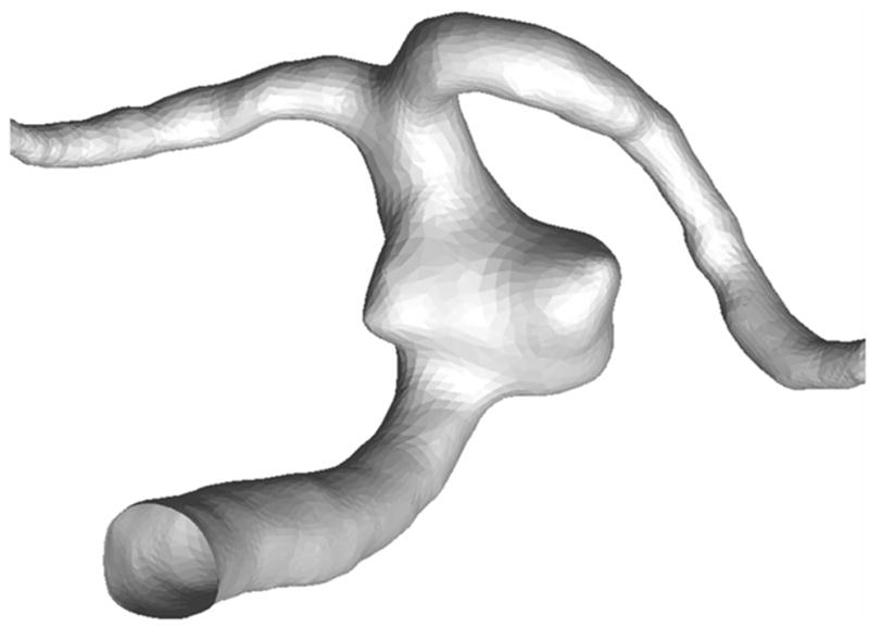
Geometry of a basilar trunk saccular aneurysm and parent artery reconstructed from a patient's CTA images.
Stent Geometry
The reconstructed aneurysm was virtually treated with 1–3 stents; an unstented scenario of the aneurysm model served as a control. The stent designs modeled by computer-assisted design (CAD) software (ProEngineer; PTC, Needham, MA) were the aforementioned intracranial self-expanding Enterprise stent (deployed 2.3 × 12 mm) and coronary balloon-mounted Vision™ stent (deployed 2.3 × 12 mm, Guidant, Santa Clara, CA). The ProE models of the straight stents are shown in Figure 2. The mean strut sizes (metal width of the stent strut) in the models were 50 μm for the Enterprise stent and 60 μm for the Vision stent. The stent porosities (the percentage of total stent wall area that is fenestrated) for the deployed stents were 94% for the Enterprise and 88.5% for the Vision stent. The stents were virtually conformed to fit into the parent vessel lumen and deployed across the aneurysm neck. A description of the unstented and stented aneurysm models, including the sequence in which the modeling was performed, is provided in Table 1. For the multiple-stent models, the struts of the additional stents were deployed to evenly divide the openings of the first stent. The geometries of all stented aneurysm models are shown in Figure 3.
Figure 2.
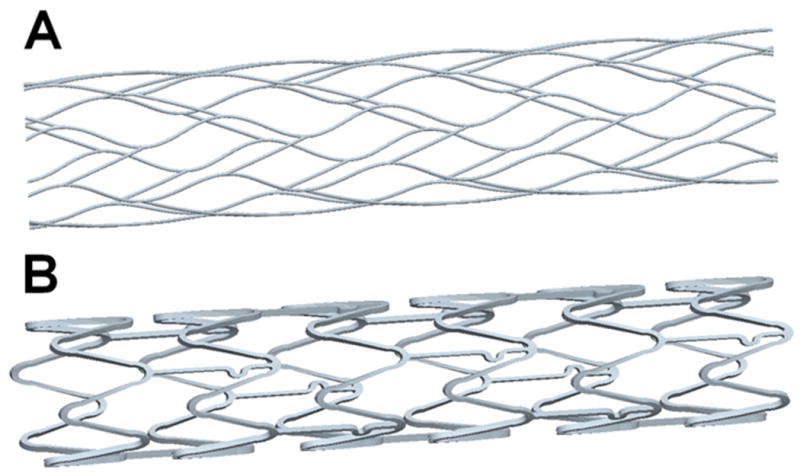
Modeled stent geometries: A) Enterprise stent, B) Vision™ stent.
TABLE 1. Unstented and stented aneurysm models.
| Sequence | Model | Model Description |
|---|---|---|
| Unstented | U | Unstented |
| Single stent | E | Enterprise stent |
| V | Vision™ stent | |
| Double stent | E2 | Two Enterprise stents |
| EV | One Enterprise and one Vision™ stent | |
| Triple stent | E3 | Three Enterprise stents |
For multiple-stented aneurysm models, each additional stent was angularly and longitudinally shifted from the previous stent position to equally divide the existing porous space so as to minimize the flow permeability of the stent combinations.
Figure 3.
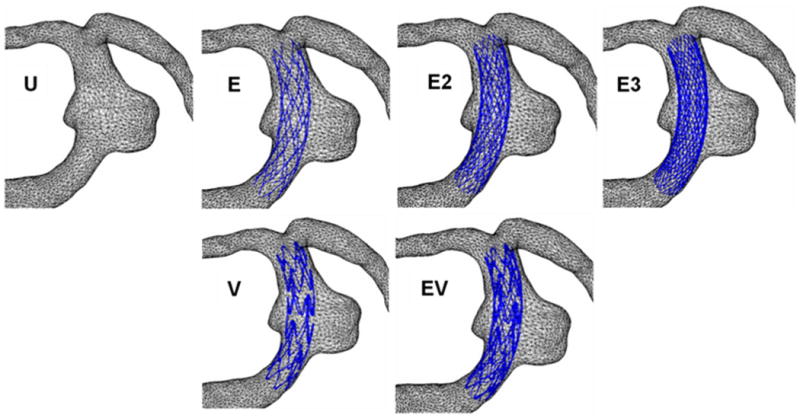
Geometries of the aneurysm models. U, unstented; E, single Enterprise stent; E2, double Enterprise stent; E3, triple Enterprise stent; V, single Vision stent; EV, Enterprise stent plus Vision stent.
CFD Modeling
Computational grids consisting of approximately 1–10 million tetrahedral elements with 0.3 mm maximum element size were created for the unstented and stented models with ICEM-CFD software (Ansys, Berkeley, CA). These grids were imported into a finite volume-based CFD code, Star-CD (CD-Adapco, Melville, NY) to solve the Navier-Stokes equations with a second-order accuracy scheme. Velocity and pressure fields were computed under the assumptions of incompressible, laminar, steady-state flow and Newtonian fluid dynamics. The Reynolds number (Re), a non-dimensional fluid dynamic similarity parameter, was 362, which is in the range of normal arterial flow conditions in the cerebrovascular circulation. The viscosity and the density of blood used in the simulations were 0.0035 kg/m sec and 1056 kg/m3, respectively.
Hemodynamic Parameters
Flow pattern, wall shear stress (WSS), magnitude of average flow velocity, turnover time, and wall pressure were used to parameterize the quantitative and qualitative effects of stenting the patient-specific aneurysm models. To illustrate the overall flow characteristics of the aneurysm, the velocity vectors in a midplane of the aneurysm models were plotted. Moreover, because the typical flow pattern in an aneurysm is rotational (Tanishita K, Ohmura.H., Ueda A, Kudo S, Tateshhima S, Ikeda M: Presentation: Frontiers of bio-fluid mechanics and mass transfer in the arterial system. Presented at the 6th World Conference on Experimental Heat Transfer, Fluid Mechanics, and Thermodynamics, April 17-21, 2005; Matsushima, Miyagi, Japan, 2005), the circulatory flow in the aneurysm was quantitatively illustrated by the vorticity contour plot on the midplane. To compare the influence of various stent combinations on the aneurysm wall, the area of elevated WSS, defined as the area where WSS is greater than the parent vessel value [8, 9], was calculated. To monitor the potential for wall deterioration through inflammation, the area of low WSS was calculated, where low-level WSS was defined as WSS <0.1 times the average value in the parent vessel [23, 40]. Intra-aneurysmal flow activity, another hemodynamic factor describing global aneurysm hemodynamics, was quantified by the volume-averaged magnitude of flow velocity in the aneurysm. To quantify stasis of flow in the aneurysm, the turnover time, which is defined as the aneurysm volume divided by the aneurysmal inflow rate at the neck, was calculated. Finally, the pressure distributions in the stented and non-stented aneurysm models were plotted.
Results
Aneurysmal Flow Pattern
From the velocity vectors plotted to visualize aneurysmal flow patterns, two distinct vortices were observed in the unstented aneurysm (Figure 4). This complex flow pattern was dampened by stenting, even with a single stent. With an increasing number of stents, the vortical flow pattern was decreased further. Moreover, the regions of high flow velocity (shown in red in Figure 4) were seen to migrate into the stent lumen as the number of stents increased.
Figure 4.
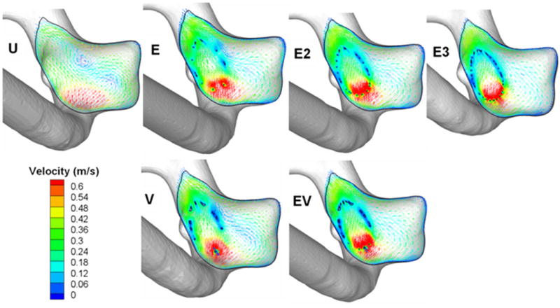
Flow patterns in the midplane of the aneurysm. U, unstented model; E, single Enterprise stent; E2, double Enterprise stent; E3, triple Enterprise stent; V, single Vision stent; EV, Enterprise stent plus Vision stent.
Detailed circulatory flow characteristics in the aneurysm are shown in Figure 5 as vorticity contours plotted on the midplane of each aneurysm model. The colors indicate the magnitude of vorticity perpendicular to the plane, with red indicating counterclockwise rotation and blue indicating clockwise rotation. The vorticity magnitude in the aneurysm dome was reduced by single stent insertion, and further reduction in vorticity was achieved by deploying additional stents. Single Enterprise or Vision stent placement resulted in a similar degree of attenuation of vorticity within the aneurysm. Likewise, two Enterprise stents reduced the vorticity by roughly the same amount as a Vision plus an Enterprise stent. Vorticity reduction was maximized when three Enterprise stents were used.
Figure 5.
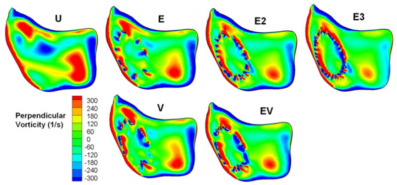
Perpendicular vorticity component in the midplane. U, unstented model; E, single Enterprise stent; E2, double Enterprise stent; E3, triple Enterprise stent; V, single Vision stent; EV, Enterprise stent plus Vision stent.
Aneurysmal WSS
Figure 6 shows the surface distribution of WSS in all models, and the average WSS on the aneurysm wall is given in Table 2 as a percentage of the unstented value. A single Vision or Enterprise stent reduced the average WSS by approximately the same amount (to 85.1 and 85.9% of the unstented value), which was further reduced by an Enterprise stent plus a Vision stent or a double Enterprise stent (69.2 and 71.3%). The triple Enterprise stent model showed the largest reduction of average WSS (54.7%). The area of elevated aneurysmal WSS is also given in Table 2 as a percentage of the value for the unstented case. In the single-stented (E or V) aneurysm models, the Vision stent reduced the elevated WSS significantly more than the Enterprise stent (reduction to 73.0% for the Vision stent and to 81.6% for the Enterprise stent). The same was true for the double-stented models, in which the Enterprise plus Vision stent combination (EV) achieved a much stronger reduction of elevated WSS (54.8%) than the double Enterprise (E2) stent model (75.6%). Thus, the E2 stent model reduced the elevated WSS slightly less than a single Vision (V) stent. Finally, the elevated WSS was reduced by the largest amount in the triple Enterprise stent model (E3) among all the models (reduction to 37.6%, compared with the unstented model).
Figure 6.
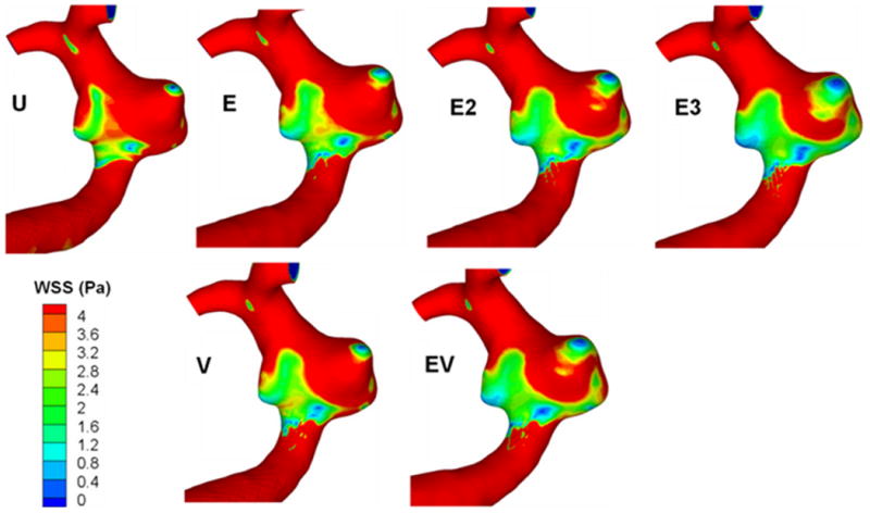
Surface distribution of wall shear stress (WSS). U, unstented model; E, single Enterprise stent; E2, double Enterprise stent; E3, triple Enterprise stent; V, single Vision stent; EV, Enterprise stent plus Vision stent.
TABLE 2. Aneurysmal flow parameters in the unstented and stented models.
| Sequence | Model | Average WSS (%) |
Elevated WSS Area (%) |
Low WSS Area† (%) |
Average Velocity Magnitude (%) |
Turnover Time (%) |
Pressure Reduction†† (mmHg) |
|---|---|---|---|---|---|---|---|
| Unstented | U | 100 | 100 | 0.11 | 100 | 100 | 0.00 |
| Single stent | E | 85.9 | 81.6 | 0.25 | 84.9 | 113.8 | 0.99 |
| V | 85.1 | 73.0 | 0.18 | 84.6 | 117.1 | 1.43 | |
| Double stent | E2 | 71.3 | 75.6 | 2.20 | 73.6 | 127.2 | 1.47 |
| EV | 69.2 | 54.8 | 0.81 | 71.2 | 128.5 | 1.94 | |
| Triple stent | E3 | 54.7 | 37.6 | 1.32 | 61.9 | 141.0 | 1.85 |
All parameters are expressed as percentages of the unstented case, except for the Low WSS Area† and Pressure Reduction††.
Given as a percentage of the entire aneurysm sac area. Low-level WSS was defined as WSS <0.1 times the average value in the parent vessel.
Given as the pressure drop from the unstented case.
Table 2 gives the aneurysmal area exposed to low-level WSS as a percentage of the total aneurysm sac area. In the unstented case, a mere 0.11% of the aneurysmal wall is exposed to low-level WSS. This area is slightly increased by stenting but remains insignificant in all cases, never exceeding 2.2% for any stent combination.
Average Aneurysmal Flow Velocity and Turnover Time
Intra-aneurysmal flow activity was quantified by the magnitude of average flow. In Table 2, the average flow velocity magnitude at the dome of each aneurysm model is given as a percentage of that in the unstented aneurysm. The diminution of inflow caused by stent placement resulted in the attenuation of flow activity in the aneurysm. Consequently, the magnitude of the average aneurysmal flow velocity was reduced. Even with a single stent, aneurysmal flow velocity reductions were substantial (reduction to approximately 85% for both stent designs). Supplementary inflow reduction and flow activity decrease were obtained by the placement of an additional stent, with the EV and E2 models achieving velocity reduction to 71.2% and 73.6%, respectively. Maximum diminution in average flow velocity was obtained after the consecutive placement of three Enterprise stents (reduction to 61.9% for the E3 model).
Additional quantification of stent-induced aneurysm hemodynamics was performed using turnover time (Table 2). The increase in turnover time in the single-stented aneurysm models was not remarkable, compared with that in the unstented aneurysm model (1.1 and 1.2 times longer for E and V models, respectively). A larger increase in turnover time, however, was obtained by double stenting (1.27 and 1.28 times longer for E2 and EV models, respectively). A turnover time of approximately 1.41 times longer than that in the unstented aneurysm model was attained in the triple-stented model (E3).
Pressure
The pressure at the vascular walls is illustrated in Figure 7 for all models, and the average pressure on the aneurysm wall is given in Table 2. The pressure decreased in all models, by an amount of 0.99 mmHg (E) to 1.94 mmHg (EV) compared to the unstented case. These pressure reductions are insignificant compared to physiological blood pressure (≈100 mmHg).
Figure 7.
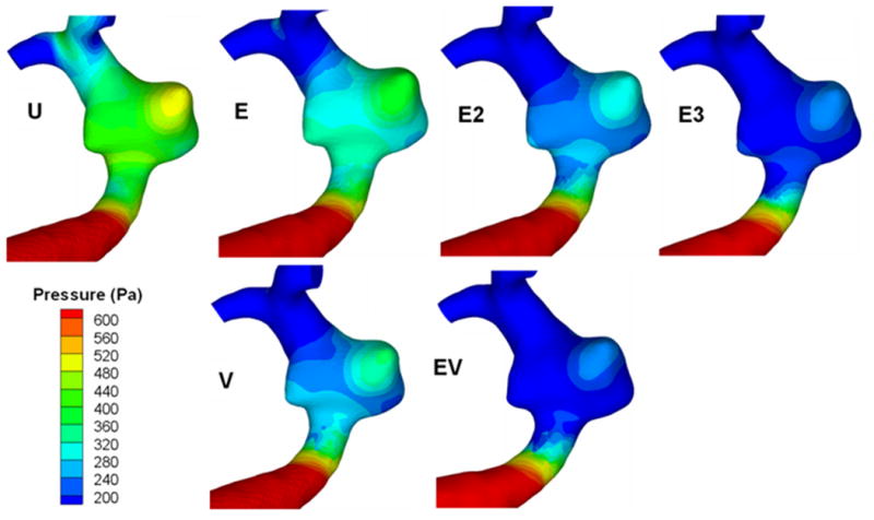
Surface distribution of pressure. U, unstented model; E, single Enterprise stent; E2, double Enterprise stent; E3, triple Enterprise stent; V, single Vision stent; EV, Enterprise stent plus Vision stent.
Discussion
Stent Monotherapy
Occasionally, small, dissecting, blood-blister-like pseudoaneurysms that are not amenable to either coil embolization or surgical clipping can be effectively treated with one or sometimes multiple overlapping stents, without embolization coils [14]. Conversely, in wide-necked aneurysms with segmental defects of the parent vessel, parent vessel reconstruction with stents remains the only endovascular option for aneurysm occlusion with vessel preservation. Recently, dedicated flow-diverting endovascular constructs designed for intracranial use have been developed, but these are still in the process of technological refinement and only available as a part of a trial at selected institutions. Therefore, currently available self-expanding microstents and more trackable balloon-mounted metal stents are being primarily used when stenting for aneurysms is required.
Although not indicated for intracranial aneurysms, the balloon-mounted stents (for example, the Vision stent) provide a greater degree of metal surface area coverage and may be more effective in diverting flow than currently available self-expanding microstents, and in ultimately providing scaffolding for tissue overgrowth. However, the trauma induced during the manipulation of these rigid coronary devices to the targeted landing zone and the relatively high-pressure balloon inflation risk perforation of the fragile intracranial vessels. In the future, highly maneuverable flow-diverting stents with higher metal surface area specifically designed for the intracranial vasculature, such as the Pipeline Embolization Device (ev3, Irvine CA) and SILK flow-diverting device (BALT, Montmorency, France), may replace these stents. At present, these devices are being tested and are not widely available. This report elaborates the hemodynamic changes with currently available devices, the Enterprise and the Vision stent, to allow safer choices when stent monotherapy is considered.
The Enterprise Vascular Reconstruction Device is a self-expanding closed-cell microcatheter-delivered nitinol microstent with superelasticity, which allows these stents to differentially expand to accommodate diametrically different adjacent vascular segments. This design provides several key advantages: 1) prior to full deployment, the device is retrievable; 2) the stent does not splay open along the outer curvature of vascular bends; and 3) each cell is incorporated into the entire device structure, making the individual cells more durable and less likely to become damaged during attempted microcatheter traversal. There are also disadvantages associated with the closed-cell construct: 1) the loss of segmental flexibility created by the continuous closed-cell structure may result in the device “kinking” or forming a “cobra-head” configuration around tight vascular curves, potentially resulting in poor vessel wall apposition and suboptimal parent vessel protection [3, 13]; and 2) the closed-cell construct exerts less chronic outward force (i.e., outward pressure upon the vessel wall), potentially making it more prone to migration during attempted catheterization of the aneurysm or in some anatomical configurations [25].
The Vision stent is a cobalt-chromium balloon-mounted coronary stent (BMCS) that has thinner struts and low stent-metal volume, when compared to previous BMCS. These devices have the following advantages: 1) a much higher degree of metal surface area coverage (Vision: 11.5%) in comparison to the self-expanding devices (Enterprise: 6%), 2) a much more rigid construct within the vessel that is more resistant to displacement or damage from other devices used during treatment, and 3) greater radiopacity than the self-expanding stents. However, BMCS are deployed through the inflation of a high-pressure angioplasty balloon, producing a much greater level of intimal and endothelial disruption.
Aneurysmal Flow Alteration through Stent Monotherapy
The primary goal of stent-alone treatment is to divert the flow away from the aneurysm, create favorable condition in the aneurysm sac to create rapid thrombotic occlusion, and subsequently reconstruct the vessel. Thereby, the flow diverter should:
Reduce intra-aneurysmal average flow velocity
Increase intra-aneurysmal flow turnover time
Although reduction of average aneurysmal flow velocity is intuitively indicative of flow activity suppression, the intra-aneurysmal flow turnover time is related to stasis, an indicator of potential of thrombotic occlusion. The turnover time is easy to calculate from CFD by dividing the aneurysm volume by the aneurysm inflow rate. Therefore, we examined whether stent placement resulted in significant increase of turnover time.
The secondary goal of stent-alone treatment is to eliminate the risk of rupture. It is particularly important that the stent placement does not alter the hemodynamics in such a way that it inadvertently increases the aneurysm's rupture risk. Although no metrics exist at present that would foretell aneurysm rupture, it is important that we monitor the intra-aneurysmal WSS to reduce high WSS regions and control for low WSS regions. These will be discussed in detail below.
Flow Turnover Time and Thrombosis
To afford lasting protection against rupture, the aneurysm needs to be hemodynamically “excluded” from the arterial circulatory system. It is expected that stents can accomplish this by generating slow recirculating flows and stimulating aneurysmal thrombosis [30]. A strong similarity was found between the intra-aneurysmal regions with CFD-predicted slow, recirculating flows and the regions of thrombus deposition observed in vivo in follow-up magnetic resonance studies [38]. As the primary goal of stent treatment is to thrombose the entire aneurysm sac, it is expected that the aneurysmal flow turnover time – an indicator of overall stasis – will increase drastically to induce thrombus formation in cerebral aneurysms [6, 18, 27]. In the present study, aneurysmal inflow and flow activity were consistently decreased by sequential stenting (Table 2). As flow activity decreases, the turnover time increases in an inverse proportion, and therefore the chance of aneurysmal thrombosis likely increases.
Wall Shear Stress and Rupture Potential
There are two hypothesized mechanisms of aneurysm wall degradation and rupture, both related to the WSS, but the relationship of aneurysmal WSS to its rupture propensity is not clearly understood and is quite controversial. Cebral et al. [9] and Shojima et al. [40] suggested that high WSS was associated with ruptured aneurysms, whereas Jou et al. [23] found that a greater proportion of ruptured aneurysms had low WSS. Our research has led us to believe that both high WSS and low WSS could contribute to aneurysm growth and rupture, and both situations should be avoided.
Prolonged high WSS is known to cause internal elastic lamina fragmentation [34] and may be responsible for cerebral aneurysm initiation and progression [36, 40]. High WSS is often associated with flow impingement on the wall [19, 21]. Therefore, blocking the impingement jet and eliminating the high WSS zone inside the aneurysm is paramount for flow-diverting stents.
The current study involves a wide-necked aneurysm with a segmental defect of the parent vessel. CFD simulations in this model show that it does not involve flow impingement either in the aneurysm sac or at the distal neck. The stents further deflected the inflow into the aneurysm and restrained the WSS elevation on the aneurysm wall. This result is consistent with our previous finding that stenting could lessen exposure of the distal aneurysm neck to high WSS [37], thus potentially deferring further expansion of the aneurysm neck.
Apart from the high-WSS-mediated destructive remodeling pathways [18, 19, 34, 37], an inflammatory and atherosclerotic pathway triggered by low WSS has also been implicated in aneurysm development and growth [4, 11, 39, 43, 44]. Excessively low WSS within the aneurysm sac could lead to atherosclerotic inflammatory infiltration [33], causing deterioration of the aneurysm wall that could ultimately lead to rupture [42]. Stenting, by lowering the average WSS and increasing the area of low WSS, could inadvertently increase aneurysm rupture risk unless the entire aneurysm is quickly thrombosed. This should be kept in mind when using stents.
In the current study, the area of low WSS was small (only 0.11% of the entire sac area). After the placement of multiple stents, the low WSS area in the dome of the aneurysm became larger but never exceeded 2.2% of the sac area. Although this area is small, it is important to recognize that we currently do not have a precise understanding of the detailed mechanobiologic mechanisms that eventually lead to aneurysm rupture. If low WSS may induce focal inflammation (and subsequent tissue destruction or degradation) in the aneurysm dome (the usual site of rupture) and primary stenting increases the low WSS area, there is a theoretical possibility that stent monotherapy could induce aneurysm rupture.
Aneurysmal Flow Pattern
Besides WSS, aneurysmal flow pattern has often been examined and related to rupture potential. Cebral et al. [9] found that ruptured aneurysms were more likely to have complex flow patterns, whereas unruptured aneurysms were more likely to have simple flow patterns. Ujiie et al. [41, 42] associated secondary flow circulation, which is often found in an aneurysm with a large aspect ratio, with increased rupture risk. Complex flow patterns have been thought to increase inflammatory cell infiltration in the aneurysmal wall, thereby increasing rupture risk [10, 20, 42]. In the present study, the flow pattern in the unstented wide-necked basilar trunk aneurysm had two distinct vortices. This complex flow pattern was simplified and the vortices suppressed by stenting with placement of 1–3 stents. This finding indicates that stent placement in this aneurysm geometry may reduce the risk of aneurysm rupture by dampening the flow complexity, even though a single stent may not be enough to induce complete aneurysm thrombosis.
Multiple Stenting
Consistent with our previous study [26], we have shown here that the flow modification effect amplifies as the number of stents sequentially deployed at the same location increases. By further decreasing intra-aneurysmal flow velocity and increasing turnover time, multiple stenting helps to create stasis condition conducive for thrombotic occlusion of the aneurysm sac. However, multiple stenting also decreases WSS. If the whole sac is not thrombosed quickly enough, there might be an increased risk of rupture.
Furthermore, although the potential risk of infarction or ischemia caused by a single stent compromising perforating branches may not be important [24, 31], as the number of stents increases, there is a greater theoretical chance for interruption of flow into perforating branches. Therefore, careful consideration for use of single or multiple stenting technique is required, taking into account the patient's neurovascular anatomy.
Limitations and Strengths of the Study
The limitations of this study are as follows: 1) The results of flow simulation performed in a single patient-specific aneurysm at a particular location may not be generalized. However, it is our hope that this work furthers our understanding of the hemodynamic changes induced by stenting. 2) The assumption in flow conditions, fluid properties, inlet velocity, and outlet flow splits for the CFD simulations were made to reflect typical conditions in the cerebral circulation but may not be applicable to all possible clinical situations. 3) Typically, when multiple stents are placed in the clinical setting, they cannot be so accurately placed as to divide the stent cells equally, as was assumed in the CFD simulations. However, it is expected that placement accuracy will further increase along with progressive development in imaging modalities and delivery techniques.
This study is akin to our previous investigation of flow alterations in conjunction with virtual placement of Neuroform, Vision, and Wingspan stents in the same aneurysm model [26]. The present study is an important improvement over the previous study, because flow dynamics modifications associated with the Enterprise stent have not been studied and that stent is the most common microstent that is widely used for flow diversion of intracranial aneurysms. Evaluation of all these stent technologies in the same model gives a reference for comparison of these technologies. In the future, advances in CFD simulation may allow virtual stenting of patient-specific anatomy and assessment of hemodynamic effects before the interventionist actually performs the procedure. This may allow safer treatment decisions to be made when flow diversion is used for aneurysm treatment.
Conclusion
The flow alterations caused by the more navigable closed-cell intracranial microstent, the Enterprise stent, have been analyzed for the first time with CFD in this study. Triple Enterprise stent placement led to the largest WSS reduction (54.7% compared to the unstented model) and the longest turnover time increase (141%) in a patient-specific model. In the single- and double-stented cases, models involving the Vision stent reduced the elevated WSS more than if only the Enterprise stent was used. Because the effect of stent placement on aneurysmal hemodynamics may adversely influence rupture risk, further studies of the biological response to stent placement are required. This may be increasingly relevant as the endovascular market is rapidly expanding to include a plethora of flow-diverting devices for intracranial aneurysms that cannot safely be coiled with currently available technology.
Acknowledgments
Sujan Dhar MS, for helpful discussions on creating stent models and Debra J. Zimmer AAS CMA-A for editorial assistance.
Funding: NIH grants NS047242 (Meng) and NS064592 (Meng, Siddiqui)
Abbreviations
- BMCS
balloon-mounted coronary stents
- CAD
computer-assisted design
- CFD
computational fluid dynamics
- CTA
computed tomographic angiography
- sec
seconds
- WSS
wall shear stress
Footnotes
Publisher's Disclaimer: This is a PDF file of an unedited manuscript that has been accepted for publication. As a service to our customers we are providing this early version of the manuscript. The manuscript will undergo copyediting, typesetting, and review of the resulting proof before it is published in its final citable form. Please note that during the production process errors may be discovered which could affect the content, and all legal disclaimers that apply to the journal pertain.
References
- 1.Ansari SA, Lassig JP, Nicol E, Thompson BG, Gemmete JJ, Gandhi D. Thrombosis of a fusiform intracranial aneurysm induced by overlapping Neuroform stents: case report. Neurosurgery. 2007;60:E950–1. doi: 10.1227/01.NEU.0000255427.08926.DC. [DOI] [PubMed] [Google Scholar]
- 2.Benndorf G, Herbon U, Sollmann WP, Campi A. Treatment of a ruptured dissecting vertebral artery aneurysm with double stent placement: case report. AJNR Am J Neuroradiol. 2001;22:1844–8. [PMC free article] [PubMed] [Google Scholar]
- 3.Benndorf G, Klucznik RP, Meyer D, Strother CM, Mawad ME. “Cross-over” technique for horizontal stenting of an internal carotid bifurcation aneurysm using a new self-expandable stent: technical case report. Neurosurgery. 2006;58:ONS-E172. doi: 10.1227/01.NEU.0000193530.95489.D8. [DOI] [PubMed] [Google Scholar]
- 4.Boussel L, Rayz V, McCulloch C, Martin A, Acevedo-Bolton G, Lawton M, Higashida R, Smith WS, Young WL, Saloner D. Aneurysm growth occurs at region of low wall shear stress: patient-specific correlation of hemodynamics and growth in a longitudinal study. Stroke. 2008;39:2997–3002. doi: 10.1161/STROKEAHA.108.521617. [DOI] [PMC free article] [PubMed] [Google Scholar]
- 5.Brassel F, Rademaker J, Haupt C, Becker H. Intravascular stent placement for a fusiform aneurysm of the posterior cerebral artery: case report. Eur Radiol. 2001;11:1250–3. doi: 10.1007/s003300000697. [DOI] [PubMed] [Google Scholar]
- 6.Burleson AC, Turitto VT. Identification of quantifiable hemodynamic factors in the assessment of cerebral aneurysm behavior. On behalf of the Subcommittee on Biorheology of the Scientific and Standardization Committee of the ISTH. Thromb Haemost. 1996;76:118–23. [PubMed] [Google Scholar]
- 7.Canton G, Levy DI, Lasheras JC, Nelson PK. Flow changes caused by the sequential placement of stents across the neck of sidewall cerebral aneurysms. J Neurosurg. 2005;103:891–902. doi: 10.3171/jns.2005.103.5.0891. [DOI] [PubMed] [Google Scholar]
- 8.Cebral JR, Castro MA, Appanaboyina S, Putman CM, Millan D, Frangi AF. Efficient pipeline for image-based patient-specific analysis of cerebral aneurysm hemodynamics: technique and sensitivity. IEEE Trans Med Imaging. 2005;24:457–67. doi: 10.1109/tmi.2005.844159. [DOI] [PubMed] [Google Scholar]
- 9.Cebral JR, Castro MA, Burgess JE, Pergolizzi RS, Sheridan MJ, Putman CM. Characterization of cerebral aneurysms for assessing risk of rupture by using patient-specific computational hemodynamics models. AJNR Am J Neuroradiol. 2005;26:2550–9. [PMC free article] [PubMed] [Google Scholar]
- 10.Chiu JJ, Chen CN, Lee PL, Yang CT, Chuang HS, Chien S, Usami S. Analysis of the effect of disturbed flow on monocytic adhesion to endothelial cells. J Biomech. 2003;36:1883–95. doi: 10.1016/s0021-9290(03)00210-0. [DOI] [PubMed] [Google Scholar]
- 11.Davies PF, Spaan JA, Krams R. Shear stress biology of the endothelium. Ann Biomed Eng. 2005;33:1714–8. doi: 10.1007/s10439-005-8774-0. [DOI] [PubMed] [Google Scholar]
- 12.Doerfler A, Wanke I, Egelhof T, Stolke D, Forsting M. Double-stent method: therapeutic alternative for small wide-necked aneurysms. Technical note. J Neurosurg. 2004;100:150–4. doi: 10.3171/jns.2004.100.1.0150. [DOI] [PubMed] [Google Scholar]
- 13.Ebrahimi N, Claus B, Lee CY, Biondi A, Benndorf G. Stent conformity in curved vascular models with simulated aneurysm necks using flat-panel CT: an in vitro study. AJNR Am J Neuroradiol. 2007;28:823–9. [PMC free article] [PubMed] [Google Scholar]
- 14.Fiorella D, Albuquerque FC, Deshmukh VR, Woo HH, Rasmussen PA, Masaryk TJ, McDougall CG. Endovascular reconstruction with the Neuroform stent as monotherapy for the treatment of uncoilable intradural pseudoaneurysms. Neurosurgery. 2006;59:291–300. doi: 10.1227/01.NEU.0000223650.11954.6C. [DOI] [PubMed] [Google Scholar]
- 15.Fiorella D, Kelly M, Woo H. Flow diversion for intracranial aneurysm treatment. Endovascular Today. 2009 September;:67–74. [Google Scholar]
- 16.Geremia G, Haklin M, Brennecke L. Embolization of experimentally created aneurysms with intravascular stent devices. AJNR Am J Neuroradiol. 1994;15:1223–31. [PMC free article] [PubMed] [Google Scholar]
- 17.Han PP, Albuquerque FC, Ponce FA, MacKay CI, Zabramski JM, Spetzler RF, McDougall CG. Percutaneous interacranial stent placement for aneurysms. J Neurosurg. 2003;99:23–30. doi: 10.3171/jns.2003.99.1.0023. [DOI] [PubMed] [Google Scholar]
- 18.Hashimoto S, Nishiguchi K, Abe Y, Nie M, Takayana T, Asari H, Kazama S, Ishihara A, Sasada T. Thrombus formation under pulsatile flow: effect of periodically fluctuating shear rate. Jpn J Artif Organs. 1990;19:1207–10. [Google Scholar]
- 19.Hashimoto T, Meng H, Young WL. Intracranial aneurysms: links among inflammation, hemodynamics and vascular remodeling. Neurol Res. 2006;28:372–80. doi: 10.1179/016164106X14973. [DOI] [PMC free article] [PubMed] [Google Scholar]
- 20.Hinds MT, Park YJ, Jones SA, Giddens DP, Alevriadou BR. Local hemodynamics affect monocytic cell adhesion to a three-dimensional flow model coated with E-selectin. J Biomech. 2001;34:95–103. doi: 10.1016/s0021-9290(00)00139-1. [DOI] [PubMed] [Google Scholar]
- 21.Hoi Y, Meng H, Woodward SH, Bendok BR, Hanel RA, Guterman LR, Hopkins LN. Effects of arterial geometry on aneurysm growth: three-dimensional computational fluid dynamics study. J Neurosurg. 2004;101:676–81. doi: 10.3171/jns.2004.101.4.0676. [DOI] [PubMed] [Google Scholar]
- 22.Howington JU, Hanel RA, Harrigan MR, Levy EI, Guterman LR, Hopkins LN. The Neuroform stent, the first microcatheter-delivered stent for use in the intracranial circulation. Neurosurgery. 2004;54:2–5. doi: 10.1227/01.neu.0000099370.05758.4d. [DOI] [PubMed] [Google Scholar]
- 23.Jou LD, Lee DH, Morsi H, Mawad ME. Wall shear stress on ruptured and unruptured intracranial aneurysms at the internal carotid artery. AJNR Am J Neuroradiol. 2008;29:1761–7. doi: 10.3174/ajnr.A1180. [DOI] [PMC free article] [PubMed] [Google Scholar]
- 24.Kallmes DF, Ding YH, Dai D, Kadirvel R, Lewis DA, Cloft HJ. A new endoluminal, flow-disrupting device for treatment of saccular aneurysms. Stroke. 2007;38:2346–52. doi: 10.1161/STROKEAHA.106.479576. [DOI] [PubMed] [Google Scholar]
- 25.Kelly ME, Turner RI, Moskowitz SI, Gonugunta V, Hussein MS, Fiorella D. Delayed migration of a self-expanding intracranial microstent. AJNR Am J Neuroradiol. 2008;29:1959–60. doi: 10.3174/ajnr.A1224. [DOI] [PMC free article] [PubMed] [Google Scholar]
- 26.Kim M, Levy EI, Meng H, Hopkins LN. Quantification of hemodynamic changes induced by virtual placement of multiple stents across a wide-necked basilar trunk aneurysm. Neurosurgery. 2007;61:1305–13. doi: 10.1227/01.NEU.0000280168.25968.49. [DOI] [PMC free article] [PubMed] [Google Scholar]
- 27.Kim M, Taulbee DB, Tremmel M, Meng H. Comparison of two stents in modifying cerebral aneurysm hemodynamics. Ann Biomed Eng. 2008;36:726–41. doi: 10.1007/s10439-008-9449-4. [DOI] [PMC free article] [PubMed] [Google Scholar]
- 28.Krings T, Hans FJ, Moller-Hartmann W, Brunn A, Thiex R, Schmitz-Rode T, Verken P, Scherer K, Dreeskamp H, Stein KP, Gilsbach J, Thron A. Treatment of experimentally induced aneurysms with stents. Neurosurgery. 2005;56:1347–60. doi: 10.1227/01.neu.0000159887.03290.d1. [DOI] [PubMed] [Google Scholar]
- 29.Lanzino G, Wakhloo AK, Fessler RD, Hartney ML, Guterman LR, Hopkins LN. Efficacy and current limitations of intravascular stents for intracranial internal carotid, vertebral, and basilar artery aneurysms. J Neurosurg. 1999;91:538–46. doi: 10.3171/jns.1999.91.4.0538. [DOI] [PubMed] [Google Scholar]
- 30.Liou TM, Liou SN. Pulsatile flows in a lateral aneurysm anchored on a stented and curved parent vessel. Exp Mech. 2004;44:253–60. [Google Scholar]
- 31.Lopes DK, Ringer AJ, Boulos AS, Qureshi AI, Lieber BB, Guterman LR, Hopkins LN. Fate of branch arteries after intracranial stenting. Neurosurgery. 2003;52:1275–9. doi: 10.1227/01.neu.0000064567.15270.27. [DOI] [PubMed] [Google Scholar]
- 32.Lylyk P, Cohen JE, Ceratto R, Ferrario A, Miranda C. Endovascular reconstruction of intracranial arteries by stent placement and combined techniques. J Neurosurg. 2002;97:1306–13. doi: 10.3171/jns.2002.97.6.1306. [DOI] [PubMed] [Google Scholar]
- 33.Malek AM, Alper SL, Izumo S. Hemodynamic shear stress and its role in atherosclerosis. JAMA. 1999;282:2035–42. doi: 10.1001/jama.282.21.2035. [DOI] [PubMed] [Google Scholar]
- 34.Masuda H, Zhuang YJ, Singh TM, Kawamura K, Murakami M, Zarins CK, Glagov S. Adaptive remodeling of internal elastic lamina and endothelial lining during flow-induced arterial enlargement. Arterioscler Thromb Vasc Biol. 1999;19:2298–307. doi: 10.1161/01.atv.19.10.2298. [DOI] [PubMed] [Google Scholar]
- 35.Mehta B, Burke T, Kole M, Bydon A, Seyfried D, Malik G. Stent-within-a-stent technique for the treatment of dissecting vertebral artery aneurysms. AJNR Am J Neuroradiol. 2003;24:1814–8. [PMC free article] [PubMed] [Google Scholar]
- 36.Meng H, Wang Z, Hoi Y, Gao L, Metaxa E, Swartz DD, Kolega J. Complex hemodynamics at the apex of an arterial bifurcation induces vascular remodeling resembling cerebral aneurysm initiation. Stroke. 2007;38:1924–31. doi: 10.1161/STROKEAHA.106.481234. [DOI] [PMC free article] [PubMed] [Google Scholar]
- 37.Meng H, Wang Z, Kim M, Ecker RD, Hopkins LN. Saccular aneurysms on straight and curved vessels are subject to different hemodynamics: implications of intravascular stenting. AJNR Am J Neuroradiol. 2006;27:1861–5. [PMC free article] [PubMed] [Google Scholar]
- 38.Rayz VL, Boussel L, Lawton MT, Acevedo-Bolton G, Ge L, Young WL, Higashida RT, Saloner D. Numerical modeling of the flow in intracranial aneurysms: prediction of regions prone to thrombus formation. Ann Biomed Eng. 2008;36:1793–804. doi: 10.1007/s10439-008-9561-5. [DOI] [PMC free article] [PubMed] [Google Scholar]
- 39.Sho E, Sho M, Hoshina K, Kimura H, Nakahashi TK, Dalman RL. Hemodynamic forces regulate mural macrophage infiltration in experimental aortic aneurysms. Exp Mol Pathol. 2004;76:108–16. doi: 10.1016/j.yexmp.2003.11.003. [DOI] [PubMed] [Google Scholar]
- 40.Shojima M, Oshima M, Takagi K, Torii R, Hayakawa M, Katada K, Morita A, Kirino T. Magnitude and role of wall shear stress on cerebral aneurysm: computational fluid dynamic study of 20 middle cerebral artery aneurysms. Stroke. 2004;35:2500–5. doi: 10.1161/01.STR.0000144648.89172.0f. [DOI] [PubMed] [Google Scholar]
- 41.Ujiie H, Tachibana H, Hiramatsu O, Hazel AL, Matsumoto T, Ogasawara Y, Nakajima H, Hori T, Takakura K, Kajiya F. Effects of size and shape (aspect ratio) on the hemodynamics of saccular aneurysms: a possible index for surgical treatment of intracranial aneurysms. Neurosurgery. 1999;45:119–30. doi: 10.1097/00006123-199907000-00028. [DOI] [PubMed] [Google Scholar]
- 42.Ujiie H, Tamano Y, Sasaki K, Hori T. Is the aspect ratio a reliable index for predicting the rupture of a saccular aneurysm? Neurosurgery. 2001;48:495–503. doi: 10.1097/00006123-200103000-00007. [DOI] [PubMed] [Google Scholar]
- 43.Vanninen R, Manninen H, Ronkainen A. Broad-based intracranial aneurysms: thrombosis induced by stent placement. AJNR Am J Neuroradiol. 2003;24:263–6. [PMC free article] [PubMed] [Google Scholar]
- 44.Walpola PL, Gotlieb AI, Cybulsky MI, Langille BL. Expression of ICAM-1 and VCAM-1 and monocyte adherence in arteries exposed to altered shear stress. Arterioscler Thromb Vasc Biol. 1995;15:2–10. doi: 10.1161/01.atv.15.1.2. [DOI] [PubMed] [Google Scholar]


