Abstract
We describe initial experiences with an in-house, fast, large field-of-view optical-CT telecentric scanner (the Duke Large field of view Optical-CT Scanner (DLOS)). The DLOS system is designed to enable telecentric optical-CT imaging of dosimeters up to 24 cm in diameter with a spatial resolution of 1 mm3, in approximately 10 minutes. These capabilities render the DLOS system a unique device at present. The system is a scaled up version of early prototypes in our lab. This scaling introduces several challenges, including the accurate measurement of a greatly increased range of light attenuation within the dosimeter, and the need to reduce even minor reflections and scattered light within the imaging chain. We present several corrections and techniques that enable accurate, low noise, 3D dosimetery with the DLOS system.
1. Introduction
Telecentric scanners consist of a light source, rotation stage, telecentric lens, and an imaging array, typically CMOS or CCD. Telecentric based area scanners have been suggested by several authors and have potential to speed up the scanning process an order of magnitude over the 1st generation scanning laser systems [1–4]. Currently such systems have limited field of view (FOV) (e.g. < 10 cm diameter [3, 5]). A variety of challenges arise when attempting to scale up the relatively small telecentric scanner to a larger scanner with FOV up to 24 cm. First, telecentric lenses have an inherent internal reflection from lenses comprising the telecentric lens which produce cross talk on the entire array amounting to approximately .1 % of the maximum intensity incident on the array. If unaccounted for, this can lead to severe errors in the image reconstructions. Equally important is the increase in dynamic range required to image larger dosimeters. The detector is responsible for capturing accurate signal levels from the unattenuated light source simultaneously with the most attenuating pathlengths of the dosimeter, where attenuation follows Beer’s Law. Typical CCD detectors have inherent dynamic range of ~60 dB, which is sufficient for dosimeters up to 10 cm. This work presents our first experiences with the scanner, and considers methods to overcome the two primary challenges described above for imaging larger dosimeters.
2. Methods
2.1. Scanner
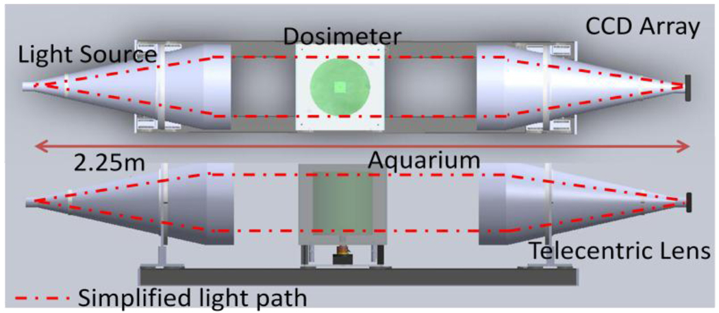
A schematic of the DLOS system is shown in figure 1. An LED light source is collimated and projected onto a dosimeter placed on a rotating stage within an anti-reflection coated glass aquarium. The aquarium is filled with a mixture of mineral oil, octyl salicylate, and octyl cinnamate such that the indices of refraction of the fluid and the dosimeter are matched to minimize reflection and refraction distortions of incident light. As the sample rotates, projection images are mapped to a CCD array via a telecentric lens, which only utilizes light rays nearly parallel (~0.1°) to the optical axis. Light rays thus pass from the source and through the dosimeter where they are differentially attenuated and continue through to the telecentric lens where they are imaged onto the 12 bit monochrome CCD array. Generally, 360 projection images with 25 averages each are acquired in 1° increments. Each projection is then flood and dark noise corrected.
Figure 1.
A schematic of the DLOS system in a top and side view showing the collimated LED light source, acquarium, rotation stage, telecentric lens and detector array.
2.2. Corrections
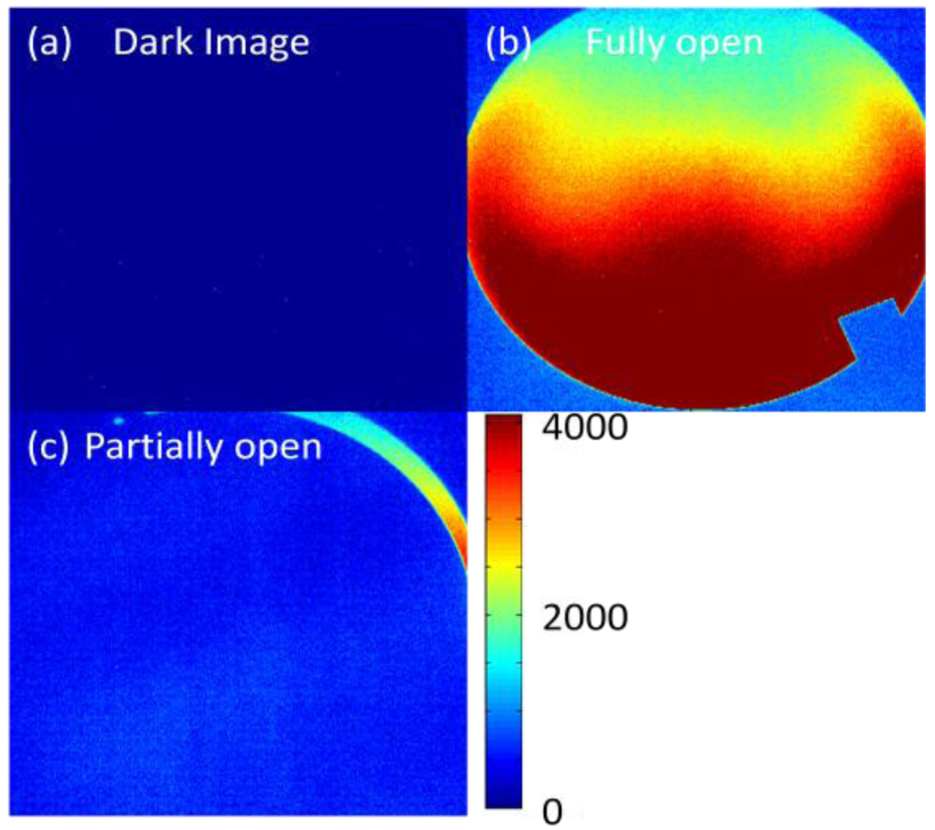
When imaging highly attenuating media, a stray light correction is required. This correction is for internal scatter caused by internal reflections within the imaging lens. Any light collected by the telecentric lens within the acceptance angle is mapped to the appropriate location. Due to internal reflections from AR coated lenses that comprise the lens, however, an approximate −50 dB signal can also be detected in the arrays other pixel locations. Figure 2 illustrates this effect. A “sliver” of light on one side of the aperture is observed to ‘spill’ over to the entire CCD array. This effect can be reduced by subtracting a scatter map of the low intensity regions created by placing an opaque structure in beam representing the higher attenuating regions of the dosimeter. This procedure achieves full dynamic range (~60 dB) from the detector and yields more accurate images.
Figure 2.
series of images showing the internal scatter present within the lens. (a) Image acquired with the lens cover on, (b) an image acquired without the lens cover and (c) an image captured with the lens cover in position to let a “sliver” of light through. Notice the contrast between (a) & (b).
When the dosimeter has a signal drop higher in magnitude than the dynamic range which the camera allows, ie > 60 dB, a separate correction needs to be introduced in combination with the stray light correction to get high dynamic range images from a low dynamic range device. The correction aims to increase the dynamic range of the system above that of the detector alone through a series of images taken with increasing exposure times, all other aspects remaining unchanged [6]. The images are converted such that pixel values are proportional to exposure rate by taking the ratio of grey scale values to exposure time. Each new image in the series replaces the previous images lower 25% exposure rates. Figure 3 shows a series of images with the intention of illustrating how the technique (combined with the previously discussed subtraction correction to account for internal scattering) can extend the inherent dynamic range of the detector. The image in figure 3a is the calculated OD of known neutral density filters placed within a filter wheel after a single exposure with no corrections applied. The image in figure 3b is an image of the same filter wheel after 3 exposures were combined to give accurate OD’s to within 3% of the expected values.
Figure 3.
(a) Image of a filter wheel with known optical densities ranging from 1 – 4 converted to OD. The OD values of ND = 1 & 2 match the known filter values, however, the higher values, ND = 3 & 4 are not near their known values. (b) An image of the same filter wheel taken with a series of 3 images with increasing exposure times to create an accurate (within 4%), high dynamic range image. This represents an image accurately covering 80 dB of dynamic range.
2.3. Irradiations, imaging & analysis
To show the DLOS system is capable of returning dosimetricly accurate images the output was compared to the images generated from MGS’s OCTOPUS scanner via 4%, 3 mm gamma analysis with a 5% threshold.
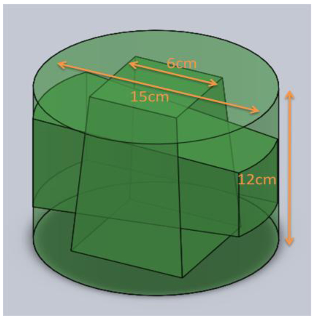
A 15 cm diameter PRESAGE dosimeter, 12 cm tall was irradiated with a simple two field plan of orthogonal 6 cm beams as shown in figure 4. The dosimeter has a sensitivity that yields a ΔOD of .06 /Gy/cm, so to match the dynamic range of the detector the dosimeter was irradiated to 2 Gy. Before irradiation, a prescan was acquired in both systems using the same refractive index matching fluid, a mixture of octyl salicylate and octyl cinnamate. Images were acquired in the DLOS system by taking an average of 16 images at each projection angle for 360 projections in one degree increments. To mimic these conditions in the MGS scanner, 360 projections were acquired in one degree increments as well. Slices were acquired 5mm apart over 15 slices covering the central 7.5 cm of the dosimeter.
Figure 4.
Sketch of the two field 6 cm × 6 cm plan delivered to the 15 cm × 12 cm dosimeter.
After irradiation the dosimeter was scanned in the DLOS system (~10 minutes) followed by a scan in the MGS scanner all with the same acquisition parameters as their respective pre scans. All images were reconstructed using the Matlab iradon function to 1 mm × 1 mm pixels. Upon image reconstructions, post and pre scans of the images were manually registered and subtracted to create a ΔOD image which isproportional to the dose delivered to the dosimeter. The two 3D data sets were then compared on a slice by slice basis with 2D gamma criteria of 4%, 3 mm. A 3D gamma analysis with identical criteria was also carried out by interpolating the MGS 5 mm gaps to 1 mm increments to match the DLOS system data set.
3. Results & Discussion
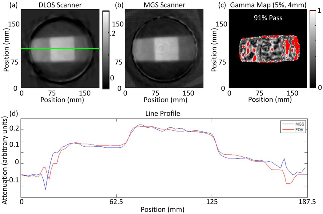
Ideally the two scanners would produce identical images. In practice this is challenging due to the differences involved in the acquiring optics among the two; however, general agreement between the two scanners is evident from figures 5a & 5b showing a representative slice from each scanner.
Figure 5.
(a) Reconstructed slice from the DLOS system. (b) The same reconstructed slice from the MGS scanner. Both scans were acquired with 360 projections over 360 degrees. (c) A 5%, 4 mm, 5% threshold for the slices shown in (a) and (b) with a 91% pass rate calculated only from pixels within the dosimeter. (d) Line profiles taken from the green line in slices (a) and (b).
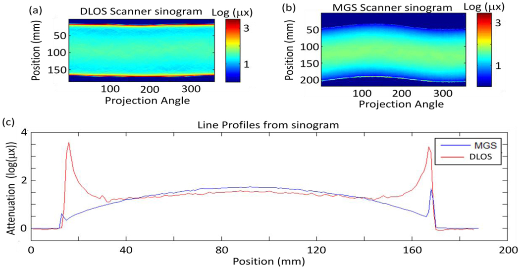
Figure 4c shows a 2D gamma comparison of the two slices showing more differences than a first glance of figures 5a & 5b may detect. The image from the laser scanner gives results that are expected by the physical setup of the system. Figures 6a & 6b show the sinograms of the slice from figure 5 for the prescans from both scanners. The sinograms are in the form of log(I0/I) and thus the grey scale values represent the amount of attenuation for each path length for a given projection angle.
Figure 6.
(a) Flood corrected sinogram from prescan captured with the large DLOS system. (b) Flood corrected sinogram from the prescan acquired with the MGS scanner & (c) a set of line profiles from each sinogram in (a) and (b) showing the differences in the scanners. Most evident are the edge artefacts present in each scanner, however, those in the DLOS system are much more pronounced and alters the shape of the curve for the 1st and last 25 mm of each projection angle. The same fluid was used in each scan and shows how the MGS scanner is much less sensitive to the refractive index match.
Two obvious differences are present in the sinograms: (1) the edge artefact is significantly more pronounced in the DLOS system and (2) the magnitude of attenuation observed is slightly higher (~10%) in the MGS scanner. Observation (1) shows that the DLOS system is much more sensitive to refractive index matching than the MGS scanner is. This is due to the relatively large collection mirror bending the laser beam after traversing the dosimeter to a collection lens which focuses the beam onto a photodiode for detection. Large changes in direction (up to ~2° can still be fully collected by the photodiode at each laser position. Conversely, when the DLOS system has the same matching fluid there is no mechanism to correct for shifts in the direction of the photons. In fact, the telecentric lens rejects any light bent more than 0.1° off the optical axis creating artificially high attenuation paths along the edges of the sinogram. The absolute attenuation difference seen in the sinograms is most likely attributable to the differences in light sources. The MGS scanner is using a very narrow bandwidth (.1 nm) 633.1 nm HeNe laser while the DLOS system is utilizing light from a 1 nm FWHM 633 nm filter from a red LED. The actual spectrum from the 1 nm is more on the order of 5 nm FWHM which can account for differences in the measured attenuation as the absorption peak for PRESAGE is 633 nm, so the laser will be preferentially attenuated.
4. Conclusion
The DLOS system was designed and built with the purpose of measuring dosimeters up to 24 cm in diameter and 20 cm in height in a short time. Initial results demonstrate a scanner with excellent spatial resolution (down to 688 µm voxels) and low noise (~10 cGy for a 2 Gy irradiation) for large dosimeters. Good agreement is observed when compared to the MGS OCTOPUS laser scanning system, when appropriate corrections are applied. Ongoing scanner commissioning work will compare DLOS 3D dosimetry for simple plans, with calculated dose distributions from a commissioned treatment planning. This work demonstrates the DLOS /Presage system has strong potential as the first large-field-of view telecentric 3D dosimetry system capable of providing high resolution 3D dosimetry in minutes.
Acknowledgement
Supported by NIH R01 CA100835
References
- 1.Doran SJ, et al. A CCD-based optical CT scanner for high-resolution 3D imaging of radiation dose distributions: equipment specifications, optical simulations and preliminary results. Phys Med Biol. 2001;46(12):3191–3213. doi: 10.1088/0031-9155/46/12/309. [DOI] [PubMed] [Google Scholar]
- 2.Oldham M, et al. High resolution gel-dosimetry by optical-CT and MR scanning. Med Phys. 2001;28(7):1436–1445. doi: 10.1118/1.1380430. [DOI] [PubMed] [Google Scholar]
- 3.Sakhalkar HS, Oldham M. Fast, high-resolution 3D dosimetry utilizing a novel optical-CT scanner incorporating tertiary telecentric collimation. Med Phys. 2008;35(1):101–111. doi: 10.1118/1.2804616. [DOI] [PMC free article] [PubMed] [Google Scholar]
- 4.Wolodzko JG, Marsden C, Appleby A. CCD imaging for optical tomography of gel radiation dosimeters. Med Phys. 1999;26(11):2508–2513. doi: 10.1118/1.598772. [DOI] [PubMed] [Google Scholar]
- 5.Clift C, et al. Toward acquiring comprehensive radiosurgery field commissioning data using the PRESAGE/optical-CT 3D dosimetry system. Phys Med Biol. 55(5):1279–1293. doi: 10.1088/0031-9155/55/5/002. [DOI] [PMC free article] [PubMed] [Google Scholar]
- 6.M Robertson SB, Stevenson L. DYNAMIC RANGE IMPROVEMENT THROUGHMULTIPLE EXPOSURES. IEEE Image Processing. 1999 [Google Scholar]


