Abstract
A method is presented to solve two-phase problems involving soluble surfactants. The incompressible Navier–Stokes equations are solved along with equations for the bulk and interfacial surfactant concentrations. A non-linear equation of state is used to relate the surface tension to the interfacial surfactant concentration. The method is based on the use of a diffuse interface, which allows a simple implementation using standard finite difference or finite element techniques. Here, finite difference methods on a block-structured adaptive grid are used, and the resulting equations are solved using a non-linear multigrid method. Results are presented for a drop in shear flow in both 2D and 3D, and the effect of solubility is discussed.
Keywords: Multiphase flows, interfacial dynamics, surfactant, soluble surfactant, surface phase, bulk phase, adsorption, desorption, complex geometry, diffuse interface, phase field, multigrid, adaptive grid, finite difference
1. Introduction
The presence of surface active agents (surfactants) at fluid interfaces can have a considerable effect on flow dynamics. Surfactants are amphiphilic organic compounds, which can be adsorbed at liquid/gas or liquid/liquid interfaces. The presence of surfactant typically alters the interface dynamics by a reduction in the surface tension of the interface. An inhomogeneous distribution of surfactants produces gradients in surface tension, which again gives rise to tangential forces along the interface. Through this so-called Marangoni effect, surfactants can play an important role in several physical phenomena such as vortex pair interaction (e.g., [1]), fingering (e.g., [2]), drop break-up and coalescence (e.g., [3, 4, 5]) and tip-streaming (e.g., [6, 4]).
From a numerical point of view, solving the problem of soluble surfactants is highly challenging. A coupled bulk/surface system of equations must be solved on a moving, complex domain, where the domain boundary may stretch, break-up or coalesce with other interfaces. Adsorption of mass to, and desorption of mass from, the interfaces poses another challenge. Further, the surface concentration may only be soluble in either the exterior or interior of the domain (e.g., amphiphilic nature of surfactants). The available numerical methods for solving these problems can roughly be divided into two categories: interface tracking and interface capturing methods. Interface tracking methods use either a separate grid for the interface, or a set of interconnected points to mark the interface. For example, boundary integral methods use a surface mesh to track the interface. In the context of surfactants, a boundary integral method for studying the effect of insoluble surfactants on drop deformation was developed in [7]. This method was extended to arbitrary viscosity ratios in [8], to 3D in [9, 4] and to soluble surfactants in [10]. See the review [11]. Another tracking method is the front-tracking method (see the review [12]), where a fixed grid is used to compute the flow, while a set of connected marker particles is used to track the interface and any interfacial quantities. A front-tracking method for insoluble surfactants was developed in [13], and this method was extended to handle soluble surfactants in [14] and [15]. A related front tracking method is the immersed boundary method (see the review [16]), which was recently used to simulate interfacial flows with insoluble surfactants using a surfactant-conserving algorithm [17]. A ghost-cell immersed boundary method was introduced in [18], and was used to study the effects of a diffusion controlled surfactant on a viscous drop injected into a viscous medium [19]. A hybrid level-set/front-tracking approach was used to study the dynamics of capillary waves with insoluble surfactant [20]. Another front-tracking method which combines a finite element methodology with adaptive body-fitted meshes was used to simulate the deformation and break-up of axisymmetric liquid bridges [21] and thin filaments [22] with insoluble surfactants. Very recently, Booty & Siegel [23] developed a hybrid numerical method to simulate bubbles in Stokes flow by combining a boundary integral method with a fixed grid solution of the bulk surfactant equation (using a mapped domain) that incorporates a singular perturbation analysis to account for the rapid variation of the bulk surfactant concentration near the interface when the bulk Peclet number is large. In general, interface tracking methods can be made very accurate but can be relatively complicated to implement, especially in three dimensions and for problems involving topological changes.
In interface capturing methods, the interface is not tracked explicitly, but instead is implicitly defined through an auxilliary function (e.g. level-set, color or phase-field function). This means that the solution of the problem can be done independently of the underlying grid, which greatly simplifies gridding, discretization and handling of topological changes. For example, a volume-of-fluid (VOF) method (see the review [24]) for insoluble surfactants was developed in [25]. A more general method which allows non-linear equations of state for surface tension was later developed in [26]. Very recently, a VOF method was developed for soluble surfactants in the limit of large sorption rates where there is an analytic relationship between the surface and bulk concentrations at the interface [27]. A level-set method [28] for solving the surfactant equation was presented in [29], and later coupled to an immersed-interface external flow solver in [30]. See the review [31] for fluid dynamics applications. An alternative approach for simulating fluid interfaces with insoluble or soluble surfactant was developed in [32, 5, 33], using the so-called Arbitrary Lagrangian-Eulerian (ALE) method (see the review [34]) together with a coupled level-set and volume of fluid method. Very recently, surfactant dynamics was simulated using a conservative smoothed particle hydrodynamics algorithm [35].
The diffuse-interface, or phase-field, method represents yet another approach for simulating solutions of equations in complex, evolving domains (see the reviews [36, 37]). In this method, which we follow here, the complex domain is represented implicitly by a phase-field function, which is an approximation of the characteristic function of the drop or matrix fluid domain. The domain boundary is replaced by a narrow diffuse interface layer such that the phase-field function rapidly transits from one inside the domain to zero in the exterior of the domain. The boundary of the domain can thus be represented as an isosurface of the phase-field function. The bulk and surface PDEs are then extended on a larger, regular domain with additional terms that approximate the adsorption-desorption flux boundary conditions and source terms for the bulk and surface equations respectively. Standard finite-difference or finite-element methods may be used. Here, we focus on a finite difference approach.
The diffuse interface method, which has a long history in the theory of phase transitions dating back to van der Waals (e.g., [38, 36, 37]), has been used to simulate multiphase flows in simple geometries including drop coalescence and break-up, electrowetting, and viscoelasticity (e.g., [39, 40, 41, 42, 43, 44, 45, 46, 47]). In [48], a diffuse interface model is implemented using a lattice Boltzmann scheme to simulate the effect of surfactant adsorption on droplet dynamics; preliminary simulations were performed. The interaction of multiphase flows with complex boundaries has also been investigated using the diffuse interface method including contact line dynamics and the effect of wetting (e.g., [49, 50, 51]). More generally, diffuse interface methods have been developed for solving PDEs on stationary surfaces [52], evolving surfaces [53, 54, 55, 56] and for solving PDEs in complex stationary [57, 58, 59] and evolving domains with Dirichlet, Neumann and Robin boundary conditions [60]. Extending previous work [58], in [61] it was shown how to solve the coupled bulk/surface problem on general, evolving domains with the diffuse interface method.
Here, we couple the diffuse interface approach from [61] with the solution of the Navier–Stokes equations, and use the method to simulate a drop in shear flow in the presence of a soluble surfactant. The method is very simple compared to previous methods, and can handle advection, diffusion and adsorption/desorption in a straightforward manner. The use of a non-linear multigrid method and block-structured, adaptive grids also make the method computationally efficient. Results are presented for a drop in shear flow in both 2D and 3D, and the effect of surfactant solubility is discussed. As observed by Milliken and Leal [10] in the context of drop deformation in extensional flows, solubility mitigates many of the surfactant effects by making the surface concentration more uniform. In particular, while an insoluble surfactant can immobilize a surface, solubility may remobilize the surface due to surfactant exchange with the bulk.
The paper is organized as follows. In Section 2, the mathematical formulaton of the problem is stated. The governing equations for the interfacial surfactant and the bulk surfactant are introduced, and the interface representation is presented. Section 3 then details the numerical implementation of the mathematical formulation and Section 4 presents some validation test cases of the method. In Section 5, a drop in shear flow is studied in detail and the effect of solubility discussed. Finally, Section 6 provides conclusions and discusses future work.
2. Mathematical formulation
2.1. Governing equations
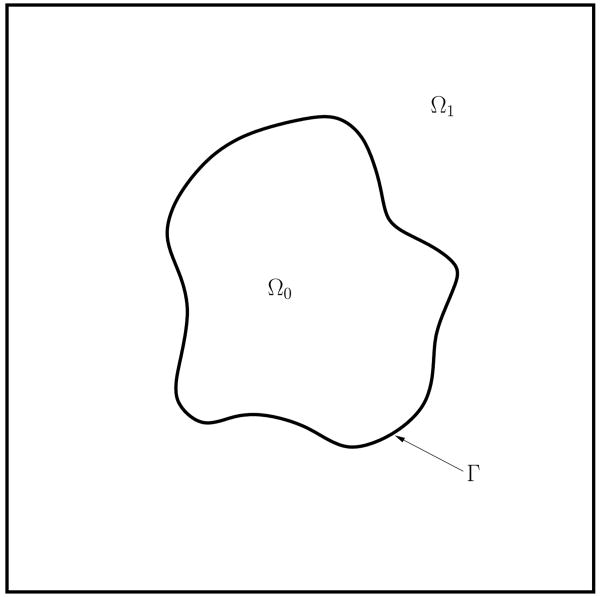
Consider a domain Ω ⊂ ℝ2,3, which contains a closed interface, Γ. The interior of the interface is Ω0 ⊂Ω, and the exterior is Ω1 ⊂Ω. See Figure 1 for an illustration.
Figure 1.
Illustration of the mathematical domain.
We assume that the flow inside the domain Ω is governed by the incompressible Navier-Stokes equations, which in dimensional form are
| (1) |
where ρ is the density, u* is the velocity, p* is the pressure, μ is the dynamic viscosity, and F* is the interfacial force, given below in Eq. (5). The density and viscosity can be discontinuous across the interface. We will only consider cases where the densities and viscosities are equal in the two phases in this work, but the discontinuity can in general be handled by interpolating their values using an indicator or characteristic function χ that varies from 0 to 1 across the interface (characteristing function of Ω1), such that
| (2) |
| (3) |
In practice, χ may be smoothed so that the transition from 0 to 1 is steep but finite. An example of a smoothed characteristic function is given in Section 2.3. Using a phase-field function c as described in Section 2.3, the governing equations can then be reposed following either the approach of Ding et al. [47] where the volume-averaged velocity is used or Lowengrub & Truskinovsky [38] where the mass-averaged velocity is used (see also [62, 63]).
We consider the deformation of an initially circular drop of radius a, placed in a shear flow of shear rate γ̇. Choosing  = a as the length scale and
  = γ̇−1 as the time scale, and
  = γ̇a as the velocity scale, the nondimensional Navier–Stokes equations can be written as
| (4) |
where Re = ρ1γ̇a2/μ1 is the Reynolds number, which measures the relative strength of the inertial and viscous forces, and Ca = μ1γ̇/σ0 is the Capillary number which measures the relative strength of the viscous and surface tension forces, where σ0 is the surface tension of a clean drop. The influence of these parameters on a clean interface has been extensively studied in the literature (e.g., [64, 65, 66, 67]). For example, as the capillary number is increased, the drop will become increasingly elongated. There exists a critical capillary number, above which the drop will no longer attain a steady shape, but continue to stretch until it breaks into smaller droplets. The value of the critical capillary number increases with increasing Reynolds numbers and viscosity ratios λ = μ0/μ1. Larger viscosity ratios serve to reduce the deformation, and for creeping flow there exists a limit where there is no critical capillary number. However, for flows with higher Reynolds numbers, break-up may still occur, due to inertial forces. In this work, we will only consider flows with moderate Reynolds numbers and viscosity ratios.
The interface force F* is given by
| (5) |
Here, σ* is the interfacial tension, I is the identity tensor and n is the outward pointing unit normal vector. δΓ is a regularized delta function, to be defined in Section 2.3. Alternately, one may write
| (6) |
where κ is the total curvature and ∇s = (I − n ⊗ n) ∇ is the surface gradient operator. The first term on the right hand side is the normal surface tension force, while the second is the tangential (Marangoni) force, which appears due to non-uniform surface tension.
Next, we assume that the interface is covered by surfactants, and we let f* denote the dimensional surfactant concentration defined on Γ. The presence of a surfactant will decrease the surface tension of the interface. We assume that the dependence of the surface tension is governed by the Langmuir equation of state,
| (7) |
where ℛ is the ideal gas constant, T is the absolute temperature, σ0 is the surface tension of a clean interface and f∞ is the maximum interfacial surfactant concentration. Let fe denote the average of f* at time t = 0. We define f = f*/fe to be the dimensionless surfactant concentration, which gives the dimensionless surface tension
| (8) |
where β = ℛ T f∞/σ0 is the elasticity number and x = fe/f∞ is the dimensionless surfactant coverage. The elasticity number is a measure of the sensitivity of the surface tension to the surfactant concentration, and thus a larger elasticity number increases the deformation. In this definition, β is independent of x, see [68].
For low surfactant concentrations, Eq. (8) can be simplified to
| (9) |
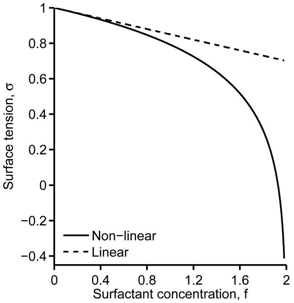
which is known as the linear equation of state. These two expressions are compared in Figure 2. We see that the expressions are similar for low surfactant concentrations, but deviate significantly for higher concentrations. Also note that for large elasticity numbers and surfactant concentrations close to 1/x, the non-linear equation of state may give unphysical (negative) values of surface tension. In [15], a minimum surface tension was introduced to alleviate this problem. However, in [69], it was argued that high elasticity numbers rarely occur in real systems. We use Eq. (8) directly for all the simulations in this work and do not encounter negative surface tension.
Figure 2.
Dependence of surface tension on surfactant concentration. Comparison of a linear and non-linear equation of state. β = 0.3, x = 0.5.
In [70], the sharp-interface representation of the surfactant mass balance equation is
| (10) |
where is the material derivative, is the tangential velocity, Df is the diffusion coefficient, and j* is the source term. Assuming that f* may be extended off Γ, the time derivative term can be changed to
| (11) |
Since
| (12) |
| (13) |
| (14) |
| (15) |
Eq. (10) is equivalent to
| (16) |
The source term, j*, is given by
| (17) |
where ra and rd are adsorption and desorption coefficients, respectively, and is the bulk surfactant concentration immediately adjacent to the surface. For dilute concentrations, this can be simplified to
| (18) |
In this work, we use the full nonlinear form in Eq. (17).
Now, assume that f* is soluble in Ω1, but not in Ω0. The bulk concentration, F*, in Ω1, evolves according to
| (19) |
with the boundary condition at Γ
| (20) |
The equation for the surface surfactant concentration, Eq. (16), can be extended to the general domain Ω. by introducing a surface delta function, δΓ, such that
| (21) |
Using that (e.g., [26])
Eq. (16) can be rewritten in distribution form as [61]
| (22) |
where it is understood that f* is extended as a constant in the normal direction off the interface. Note that in the diffuse interface reformulation of Eq. (22) this is indeed the case to leading order in the interface thickness [61]. The formulation given by Eq. (22) is considerably simpler than the sharp-interface formulation.
Similarly, the bulk concentration equation (19) can be extended to Ω. by using the characteristic function χ
| (23) |
In distribution form, Eq. (19) becomes
| (24) |
where the boundary condition has been included using the approach from [60, 61].
Let F = F*/Fe be the dimensionless surfactant concentration in the bulk fluid, where Fe average of the initial bulk concentration. Then, Eqs. (22) and (24) can be written in dimensionless form as
| (25) |
| (26) |
where Pef = γ̇a2/Df is the surface Peclet number, PeF = γ̇a2/DF is the bulk Peclet number and h = fe/(aFe) is the adsorption depth. The dimensionless source term, j, is given by
| (27) |
The dimensionless parameters are Bi = rd/γ̇ (Biot number) and k = raFe/rd (adsorption number). In our simulations, we assume that fe and Fe are in equilibrium such that j*(fe,Fe) = 0. Consequently, the following relations hold:
| (28) |
| (29) |
An insoluble surfactant may be characterized by Bi = 0. The Biot number is the ratio of the desorption rate to the interfacial surfactant convection due to shear. For large Biot numbers, there is strong coupling between the surface and the bulk.
2.2. Interface representation
To represent the interface implicitly, we may either use a level-set function or a phase-field function. For example, taking r(x,t) to be a signed distance function from Γ to x, the interface Γ is the r = 0 isosurface. Alternatively, using a phase field function c, which is 1 in Ω0 and 0 in Ω1, we may define . We follow the latter here and evolve the phase field function using an advective Cahn-Hilliard equation
| (30) |
| (31) |
where is a mobility function, and g = c2(1 − c)2/4 is a double well potential. The function μc is called the chemical potential and ε is a small parameter related to the interface thickness. Note that the above equation system is fourth-order and non-linear, which requires specialized numerical methods to solve in an efficient manner. Note that for small ε, the following relation holds near Γ
| (32) |
2.3. Regularized delta and characteristic functions
To be able to evaluate Eqs. (3), (25) and (26) numerically, regularizations of the surface delta function and characteristic function are needed. In the phase-field context, several definitions of the delta function are available from the literature. In this work, the approximation from [52],
| (33) |
is used for the surface equation. For the surface tension term and the boundary condition in the bulk equation, the approximation
| (34) |
is used. This is to avoid any scaling of the equations. Note that in the surface equation (25), the constants in Eq. (33) cancel out in the discretized equations.
The regularized characteristic function, is simply taken as [60]
| (35) |
In [61], it was shown that the regularized equations for the interfacial surfactant and the bulk surfactant converge to the sharp interface equations in the sharp interface limit.
3. Numerical methods
This section briefly describes the numerical methods used to solve the above equations. The algorithm follows that developed in [71]. In particular, the equations are discretized using finite differences in space and a semi-implicit time discretization. All variables are defined at cell-centers. A block-structured, adaptive grid is used to increase the resolution around the interface in an efficient manner. The nonlinear equations at the implicit time level are solved using a non-linear Adaptive Full Approximation Scheme (AFAS) multigrid algorithm.
Special care has to be taken for the temporal discretization. The Cahn-Hilliard system is fourth order in space, and requires the use of an implicit method to avoid severe limitations in the time step. Here, we employ a combination of explicit Adam-Basforth schemes for the convective terms and implicit Crank-Nicholson schemes for other terms.
First, the Cahn-Hilliard system is solved to find the phase-field function at the new time step. This is solved using
| (36) |
| (37) |
The operator ∇d represents the standard, second-order, finite-difference discretization. The convective terms of the form, ∇ · (uϕ), are discretized using the third-order WENO reconstruction method [72, 73]. The WENO reconstruction method has the advantage that it handles steep gradients well, which may occur in the type of dynamics described in this work. Additionally, fewer grid points are needed to achieve a high order solution. This is particularly important for the efficiency of the adaptive grid, because fewer ghost cell values have to be calculated at the boundaries of each grid block.
The velocities and concentration at the half-step are found by extrapolation, and . The velocities at the cell-edges are needed to construct the convective term. These are found by
| (38) |
| (39) |
where Ψ is the MAC projection found by solving
| (40) |
with ∇Ψ · n = 0 on ∂Ω. (assumed to be along Cartesian directions). In the AFAS nonlinear multigrid method used to solve Eqs. (36)-(37), the non-linear term in the chemical potential equation, g′(ck+1), is linearized in the smoother (local linearization) by
| (41) |
where m is the V-cycle iteration index. See [71] for details.
Next, the surfactant concentration on the surface and in the bulk at the new time step is found. Because of the regularized delta functions and characteristic functions, no special treatment of these equations are needed. We use the method from [61], and solve
| (42) |
| (43) |
as a coupled system, where we use χ = 1 − c. The source terms at the new time step are lagged in the V-cycle of the multigrid algorithm [61], i.e. jk+1 ≈ jk+1,m−1 where m is the V-cycle iteration index. This did not degrade the multigrid performance, the residual is typically reduced by an order of magnitude for each iteration.
The Navier–Stokes equations are solved using a second-order projection method. The details can be found in [74, 75, 45].
3.1. Mesh adaptivity
We use block-structured, adaptive mesh refinement to increase the resolution around the interface in an efficient manner. Near the interface, patches of overlapping, uniform, Cartesian grids are applied.
At every time step, we check grid cells for refinement using a simple undivided gradient test. Since it is essential for our problem to have a fine resolution in the diffuse interface region, this test marks grid cells where the finite difference of the phase-field function is large. In particular, we mark a cell for refinement if
| (44) |
where Ck is the tolerance for level k. We note that more sophisticated refinement criteria could also be applied. For instance, [76] used a criteria based on curvature and vorticity with a level-set method. It may also be important to refine where finite differences of f and F are large; in particular this is needed when Pef and/or PeF are large. After the cells are marked for refinement, they are grouped together into rectangular patches, and populated with data from the old grid. For a detailed discussion of all the aspects of the adaptive algorithm, the reader is referred to [71].
4. Code validation
In this section, three test cases are presented to validate the proposed numerical method. Because the bulk/surface coupling was thoroughly tested in [61], we will here focus on validating the flow solver and the coupling between the flow solver and the surfactant concentration.
In the numerical implementation, surface quantities are defined at grid points near the interface. To find values on the interface, we use a marching squares algorithm (see e.g. [77]) to generate a set of points on the 0.5 isocontour of the phase-field function. Bilinear interpolation is then used to interpolate the grid values of the surface concentration to these interface points.
4.1. Oscillations of a capillary wave
First a two-phase system without surfactants is considered to test the Navier–Stokes solver and the adaptive grid algorithm. The test problem is the damping of a sinusoidal, capillary wave. For the case of small amplitudes and matched viscosities, an analytical solution for the amplitude was found in [78].
The frequency of a wave with wavenumber k = 2π/λ, where λ is the wave length, is given by
| (45) |
Assuming the amplitude is small, the analytical solution for the amplitude a(t) is given in dimensional form by
| (46) |
where the zi's are the four roots of the algebraic equation
| (47) |
and Zi = (z2 − z1) (z3 − z1) (z4 − z1) with Z2,Z3,Z4 obtained by circular permutation of the indices. Further, b is given by
| (48) |
Here, we will consider a computational domain given by a unit square box, with an interface given by
| (49) |
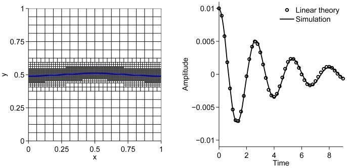
We choose dimensional variables ρ0 = ρ1 = 18.3, μ0 = μ1 = 0.078 and σ = 1.0, giving . Periodic boundary conditions are used in the horizontal direction, no-slip boundary conditions are imposed on the upper and lower boundaries, and an interface thickness parameter of ε = 5 × 10⁻³ is used along with a time step of Δt = 5 × 10⁻³.
The initial condition is shown in Figure 3 (left). An adaptive grid with 16 × 16 grid points at the root level and three levels of mesh refinement are used (hmax = 6.25 × 10⁻² and hmin = 7.8125 × 10⁻³). There are 8-10 grid points across the interface layer. Figure 3 (right) shows the evolution of the amplitude compared to the analytical solution. The numerical method is clearly capable of accurately simulating the oscillatory behavior.
Figure 3.
Capillary wave test case. An adaptive grid with root level 16 × 16 and three levels of refinement are used. ε = 5 × 10⁻³. Left: Computational domain with intial interface position and adaptive grid; Right: Amplitude of capillary wave, simulation versus linear theory.
4.2. Rising drop in a linear surfactant gradient
In [79], an approximation for the rise velocity of a viscous drop in a linear temperature gradient was found. This approximation is used here to test the implementation of the Marangoni stresses. Instead of a temperature gradient, the interfacial surfactant concentration is assumed to vary linearly in the vertical direction.
In dimensional variables, consider an axisymmetric drop of radius R in a channel of radius 5R and height L = 15R. Let the interfacial surface concentration be given by
| (50) |
and the relationship between surfactant and surface tension as
| (51) |
then an approximation for the terminal rise velocity is [79]
| (52) |
We choose dimensional parameters ρ0 = ρ1 = 0.2, μ0 = μ1 = 0.1, R = 0.5, σs = 1.0 and βs = 1.0. According to Eq. (52), this should give a Reynolds number of Re = 0.0889, which is well within the creeping flow regime for which the equation is valid.
Because of the relatively large domain needed to keep the boundary conditions from interfering with the solution, this test case lends itself very well to an adaptive grid. Here, a root level grid spacing of hmax = 5/64 = 7.8125 × 10⁻² is chosen with three levels of refinement hmin = 5/512 = 9.76 × 10⁻³. The number of nodes is approximately 9000 throughout the simulation, compared to the 196608 nodes needed for a uniform grid. An interface thickness parameter of ε = 6.0 × 10⁻³ is used (8-10 grid points across the interface), and the time step is Δt = 5.0 × 10⁻⁴. The rise velocity is calculated by
| (53) |
where ez is the unit vector in the z-direction. This integral was evaluated using the midpoint rule.
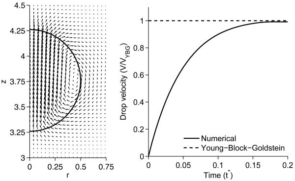
The velocity field around the drop at steady state is shown in Figure 4 (left). The figure is in good agreement with the corresponding Figure 10a in [15]. Figure 4 (right) shows the normalized rise velocity. After an initial acceleration phase, the velocity approaches the theoretical prediction asymptotically.
Figure 4.
Velocity field at steady state shown every fourth grid point (left) and rise velocity versus time (right), compared to the theoretical result, for the linear surfactant gradient test case.
Assuming the pressure in the surrounding fluid is zero, the pressure inside the drop is given by
| (54) |
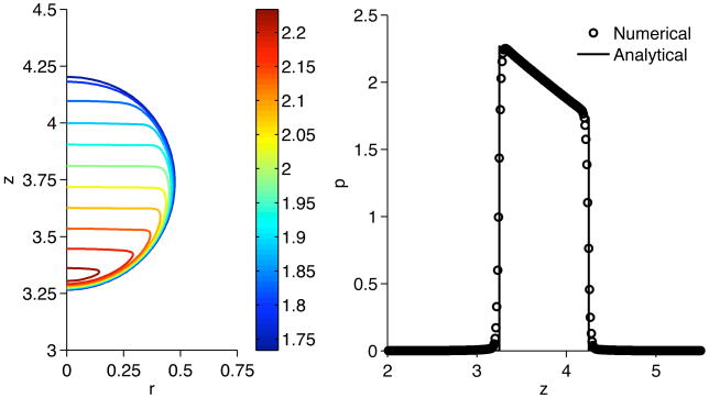
Figure 5 shows a closeup of pressure contours inside the drop (left), and the pressure along the vertical center line compared to the analytical result (right). Good agreement is observed.
Figure 5.
Pressure after one time step for a drop rising in a linear surfactant gradient. Left: Pressure contours (color online), Right: Pressure along vertical centerline compared to analytical result, Eq. (54).
4.3. Drop stretching in linear flow
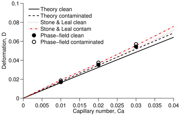
In [7], an expression was presented for the deformation of a surfactant-covered drop in the creeping flow limit under the assumptions Ca ≪ 1, Pef ≪ 1 and λ = O(1). This can be written as
| (55) |
where L and B denote the drop extension along the z and x axes, respectively, and the coefficient br is given by
| (56) |
Here, we simulate a 3D drop in a velocity field given by u = (−x, −y, 2z), with varying Ca. The viscosity ratio is set to λ = 1 and the surfactant parameters are Pe = 0.1 and β = 0.5. Due to symmetry, we only simulate one octant of the drop, and the domain size is 4R × 4R × 4R. We use an adaptive mesh with three levels of adaptivity, where the finest level has grid spacing h = 1/64. The interface thickness parameter is ε = 0.025.
Figure 6 shows the simulated results together with small deformation theory and results from [7]. We see that there is good agreement with the theory at low Ca and then the discrepancy gets larger at higher Ca. Our results are also in good agreement with the boundary-integral simulations of [7].
Figure 6.
Comparison of small deformation theory and numerical simulations for a drop stretching in linear flow.
5. Influence of soluble surfactant on drop deformation and break up in shear flow
In this section, we consider the deformation of an initially circular drop placed in a shear flow. We begin by presenting 2D results. The (nondimensional) computational domain chosen for the simulations is a rectangular domain of size 12 × 4. The nondimensional velocity, u = y is imposed on the upper and lower boundaries, and periodicity is assumed in the horizontal direction. In effect, we are simulating an infinite array of drops placed 8 units (in drop radii) apart. The root level grid spacing is hmax = 1/16, and three levels of refinement are used (hmin = 1/128), unless otherwise specified. The interface thickness parameter is ε = 1/160, and we choose a time step of 1 × 10⁻³. There are approximately 8-10 grid points across the interface layer. We use Ca = 0.5, Re = 1.0, viscosity ratio λ = 1.0, and Pef = 10 for all simulations unless otherwise noted.
5.1. Insoluble surfactant
First, we compare the evolution of a clean drop with a drop covered with insoluble surfactant using Bi = 0. We take β = 0.3, x = 0.5 and the initial surfactant distribution to be uniform: f∣t=0 = 1.0.
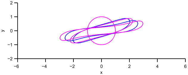
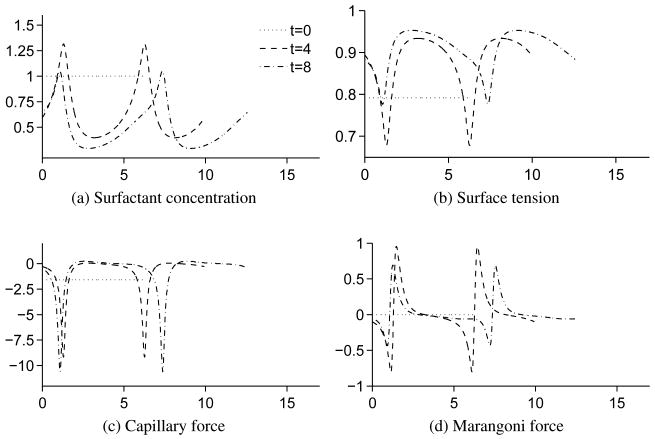
Figure 7 shows the morphology of a clean drop and an insoluble surfactant-covered drop at times 0, 4 and 8. As expected, the surfactant-covered drop exhibits a larger deformation and rotates faster due to the lower surface tension. Figure 8 shows the surface quantities surfactant concentration, surface tension, capillary force and Marangoni force as a function of arc length s at times 0, 4 and 8. The point s = 0 corresponds to the point y = 0 on the right side of the drop and s increases counterclockwise along the drop. The capillary forces are calculated as , while the Marangoni forces are calculated as , where t is the unit tangential vector. Surfactant is swept to the drop tips, which lowers the surface tension. This reduces the drop the resistance to stretching. Correspondingly, the drop thins, elongates and rotates. The capillary forces reach a maximum at the tips due to the high curvature. The presence of surfactant does not alter the capillary forces significantly, but does lower the forces near the tips (not shown). Due to symmetry, the Marangoni forces are zero at the drop tips. Near the tips, the Marangoni force has local maxima and minima. The maxima occur on the upper part of the drop interface near the right tip and on the lower part of th interface near the left tip. The minima occur on the lower region near the right tip and the upper region near the left tip. The velocity near the maxima is larger, which leads to increased surfactant convection and thereby larger surface tension gradients.
Figure 7.
Comparison of drop shapes for clean and insoluble surfactant-covered drops in a shear flow at times t = 0,4,8. Blue: Clean, Magenta: Insoluble-surfactant-covered. Color online.
Figure 8.
Surface quantities as a function of arclength for a insoluble surfactant-covered drop in shear flow.
A common problem with interface capturing methods is that they do not exactly conserve mass. In the above simulation, there is about a 0.3 % loss of surfactant mass throughout the simulation. The mass is measured by evaluating mf = ∫Ω BfdΩ using the midpoint rule. In [30], a simple mass correction scheme was used where the surfactant is multiplied by a constant to preserve mass. This scheme could also be easily adapted to our approach. The mass loss for the phase-field concentration was only 5.6 × 10⁻⁵% (measured by the total integral ∫Ω c dΩ using the midpoint rule).
5.2. Soluble surfactant
We next investigate the effect of surfactant solubility. We again take β = 0.3, x = 0.5, and the initial surface surfactant distribution to be uniform: f∣t=0 = 1.0. The adsorption number is k = 1.0 and the adsorption depth is h = 0.5. We take the drop to be in equilibrium with the bulk at the start of the simulation, i.e. j∣t=0 = 0, which gives the initial bulk concentration F∣t=0 = 1.0. We vary the Biot number and the bulk Peclet number.
5.2.1. Influence of Biot number
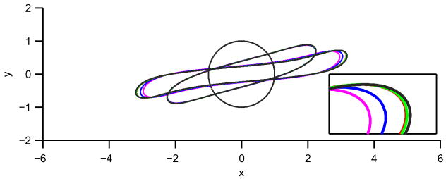
We first set the bulk Peclet number PeF = 1, and vary the Biot number. The morphology of the drops for varying Biot numbers is shown in Figure 9. The inner (magenta) drop corresponds to Bi = 0 and the outer drop (black) corresponds to Bi = ∞, simulated by enforcing f = 1 throughout the simulation. The drop deformation is an increasing function of Bi. The reason for this is that surfactant adsorption/desorption decreases the surface tension gradients and hence Marangoni forces. If the Biot number tends to infinity, the surface surfactant should be uniform and the Marangoni force vanishes.
Figure 9.
Comparison of drop shapes for various Biot numbers. The times shown are t = 0,4,8. Magenta: Bi = 0 (insoluble), blue: Bi = 0.1, red: Bi = 1, green: Bi = 10, and black: uniform (Bi = ∞). The inset shows a close-up of the drop tip for t = 8. Color online.
This is further elucidated in Figure 10. The left column of Figure 10 shows the surfactant concentration, the surface tension, the capillary force and the Marangoni force at t = 4. We see that by increasing the Biot numbers, the surfactant concentration becomes more uniform. This leads to lower surface tension gradients and thereby lower Marangoni forces, which enables the drop to deform more. The capillary force is dominated by the curvature, and remains largely unaffected by the variation in surface tension.
Figure 10.
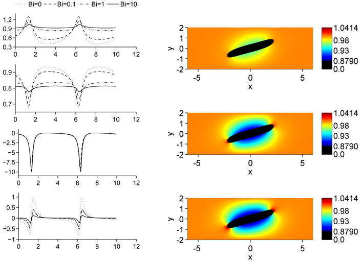
Influence of the Biot number on a drop in shear flow at t = 4. Left column shows from top to bottom: Surfactant concentration, surface tension, capillary force and Marangoni force. The right column shows the bulk surfactant concentration, from top to bottom: Bi = 0.1,Bi = 1 and Bi = 10.
The right column of Figure 10 shows the bulk concentration at t = 4. It is evident that a larger Biot number leads to a faster depletion of bulk surfactant due to the higher adsorption at the interface. At the drop tips, there is desorption of surfactant off the interface leading to increased surfactant concentration in the bulk. Also note that the change in dynamics from Bi = 1 to Bi = 10 is not as significant as the change from Bi = 0.1 to Bi = 1. This is because the bulk diffusion is not large enough to maintain a high adsorption/desorption rate. The process has become diffusion-limited.
5.2.2. Influence of Peclet number
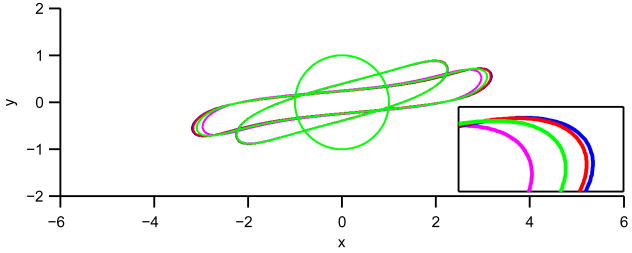
Next, we examine the effect of the bulk Peclet number PeF. The Biot number is Bi=1. Figure 11 shows the morphology of the drops for varying Peclet numbers. The deformation is larger for smaller Peclet numbers since stronger diffusion in the bulk enables the redistribution of bulk surfactant to maintain a more uniform bulk distribution. This in turn supports a larger rate of surfactant adsorption along the drop sides that keeps the surface surfactant concentration more uniform and thus decreases the Marangoni force.
Figure 11.
Comparison of drop shapes for various Peclet numbers. The times shown are t = 0,4,8. Magenta: Insoluble, blue: PeF = 0.1, red: PeF = 1 and green: PeF = 10. The inset shows a close-up of the drop tip for t = 8. Color online.
The left column of Figure 12 shows the surfactant concentration, the surface tension, the capillary force and the Marangoni force at t = 4. Again, we see that the surface surfactant concentration becomes more uniform due to the mass transfer process when the Peclet number is smaller, thereby decreasing the Marangoni forces. However, the effect is most pronounced away from the drop tips. At the drop tips, the surfactant concentration (surface tension and Capillary force) are somewhat insensitive to PeF because convection is relatively more important here than on the sides. In particular, at the sides surfactant is adsorbed to the interface, then swept by convection towards the tips, leaving room for more adsorption along the sides. This depletes the bulk concentration near the sides but at the tips, there is increased bulk concentration above F∞ = 1 because surfactant desorbs to the bulk. A small Peclet number is needed to redistribute bulk surfactant to maintain a more uniform bulk distribution and thus a high adsorption rate along the drop sides. In fact, when the Peclet number is small, the adsorption rate is not large enough to adsorb all the available bulk surfactant. Thus the differences between the results from PeF = 0.1 to PeF = 1 are less pronounced than the differences from PeF = 1 to PeF = 10. This is because the process becomes adsorption-limited for small Peclet numbers.
Figure 12.
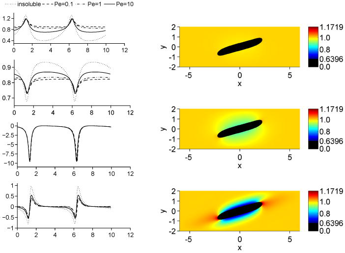
Influence of bulk Peclet number on drop in shear flow at t = 4. Left column shows from top to bottom: Surfactant concentration, surface tension, capillary force and Marangoni force. The right column shows the bulk surfactant concentration, from top to bottom: PeF = 0.1,PeF = 1 and PeF = 10. Color online.
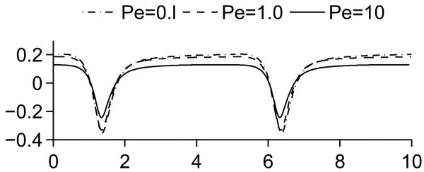
This is further illustrated in Figure 14, which shows the source term j for the three Peclet numbers. Away from the drop tips, j is positive, which means that surfactant is transported from the bulk to the interface. At the tips, the transportation is reversed due to the accumulation of surfactant here. For a high Peclet number, the mass transfer is lower, because the bulk diffusion is not large enough to transport desorbed surfactant away from the interface or to replenish surfactant adsorbed to the interface. This effect is even more pronounced when the Peclet number is significantly increased to PeF = 1000 as seen in Figure 13. At this large Peclet number, a narrow boundary layer of depleted bulk surfactant is observed along the drop sides while the bulk concentration is significantly increased near the drop tips. In order to simulate this case, another level of refinement is required such that hmin = 1/256 and in addition the mesh is refined where the undivided gradient of F is sufficiently large; the finest mesh covers the surfactant boundary layer. The thickness of the surfactant boundary layer along the drop sides is approximately 0.14 while at the drop tips the boundary layer thickness is approximately 0.69. For reference, the thickness, O(ε), of the diffuse interface describing the drop boundary is approximately 0.06.
Figure 14.
Comparison of the source term j along the interface for different Peclet numbers.
Figure 13.
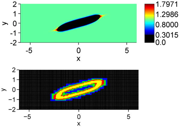
Influence of large bulk Peclet number PeF = 1000 on a drop in shear flow at t = 4. Top: Bulk surfactant distribution, Bottom: Adaptive mesh. Four levels of refinement are used (black: level 0, blue: level 1, green: level 2, red: level 3, yellow: level 4). Color online.
5.2.3. Convergence study
A convergence study was carried out for the fluid velocity, the interface surfactant and the bulk surfactant for the case where PeF = 1 and Bi = 1. Since the analytical solution is not available, we use the solution for a fine mesh as a reference solution and measure the deviation from this solution in the L2 norm. The L2 norm is calculated as
| (57) |
and the rate of convergence as
| (58) |
where h denotes grid spacing. All simulations here are carried out on a uniform mesh. Since the variables are collocated, they do not coincide when the mesh is refined. Linear interpolation is used to interpolate the values.
The results are summarized in Table 1. The rate of convergence is around two for the velocities and one for the surfactant concentrations. The result for the surfactant concentrations are in line with what was found in [61].
Table 1.
Error in L2 norm and convergence rate for the fluid velocities and the surfactant concentrations.
| Grid | ‖u − uref‖2 (×10−2) |
Rate | ‖v − vref‖2 (×10−1) |
Rate |
|---|---|---|---|---|
| 1/16 | 4.03 | - | 8.49 | - |
| 1/32 | 1.84 | 1.13 | 5.20 | 0.71 |
| 1/64 | 0.503 | 1.87 | 1.57 | 1.73 |
| 1/128 | 0.0754 | 2.74 | 0.203 | 2.95 |
| ‖f − fref‖2 (×10−1) |
Rate | ‖F − Fref‖2 (×10−1) |
Rate | |
| 1/16 | 2.93 | - | 5.96 | - |
| 1/32 | 2.23 | 0.39 | 3.64 | 0.71 |
| 1/64 | 1.58 | 0.50 | 1.19 | 0.92 |
| 1/128 | 0.686 | 1.20 | 0.834 | 1.20 |
5.3. Three-dimensional results
Finally, we present some results from three-dimensional simulations. In particular, we investigate drop break up in a shear flow. The grid spacing at the root level is hmax = 1/4, three levels of refinement are used such that hmin = 1/32. To elucidate the effects of the interface thickness parameter ε, we simulated two different cases: ε = 1/80 and 1/40. There are approximately 5-6 grid points across the interface for smaller ε. These simulations took approximately 3 days to complete on one core of an Intel i7 processor.
We take Ca = 0.42 and Re = 0.4, which while smaller than used in 2D are still above the critical threshold for the existence of steady state solutions. This allows us to run the simulation until the drop breaks up to demonstrate the ability of our method to handle topological changes. A similar simulation was presented in [66], although their simulation used Re = 0. For the surfactant, we assume a dilute concentration of x = 0.1 and a relatively strong coupling between surfactant and surface tension with β = 0.2. For the parameters associated with solubility, we again choose initial conditions at equilibrium, k = 1/9 and h = 0.9. The bulk Peclet number is set to PeF = 10.
The results for a clean drop and a drop covered by an insoluble surfactant are shown in Figure 15 (left and right columns respectively). After an initial regime of stretching, necks form near the two drop tips. These become thinner until the drop breaks up. In each case, two tiny satellite drops can be observed after the necks pinch off. In the surfactant case, the satellite drops are very small and are covered with nearly uniform surfactant. We see that the surfactant-covered drop breaks up at an earlier time. There are two principal reasons for this behavior. First, the non-uniform distribution of surfactant leads to larger deformation, as shown in the previous sections, which thins the drop more than the clean case. Second, in the necks, the surfactant concentration is low, which gives a larger surface tension (similar to the surface tension of a clean drop). Since the necks are thinner in the surfactant-laden drop this leads to faster breakup.
Figure 15.
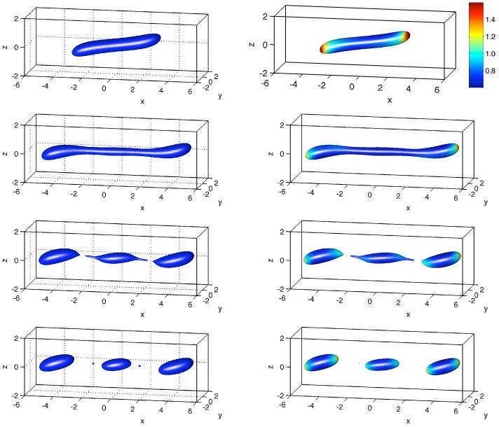
Three-dimensional simulation of a drop in shear flow with interface thickness ε = 1/80. The left column shows a drop with no surfactant. The right column shows a drop with insoluble surfactant. The times shown are from top to bottom: 10, 25, 34, and 35.16.
In Figure 16, the break-up of a clean drop is shown for a larger value of interface thickness ε (ε = 1/40 compared to ε = 1/80 in Figure 15). For the larger value of ε, the drops break up at an earlier time and satellites are not observed since they are not resolved by this value of ε. A similar behavior is observed in the presence of surfactant.
Figure 16.

Drop evolution in shear flow without surfactant at times t = 25 (left) and 35.16 (right) with ε = 1/40. All other parameters are the same as in Figure 15.
The results for soluble surfactant are shown in Figure 17, using ε = 1/80. The right column, which shows a slice of the bulk concentration, indicates that surfactant is adsorbed to the surface at the middle of the drop, and desorbed at the tips. This leads to a more uniformly distributed surfactant concentration. Comparing Figure 17 with Figure 15 we can see the soluble-surfactant-covered drop breaks up at a later time than the clean drop and the drop with insoluble surfactant. The principle reason is the adsorption and desorption of surfactant. Since adsorption occurs over a larger surface area than desorption, which just occurs at the drop tips, the interfacial surfactant concentration becomes larger across the entire drop. This means that the deformation becomes larger and that there is significant concentration of surfactant near the drop necks. This slows the thinning of the necks since the surface tension is smaller. Thus, the drop breaks up at a later time than for the clean drop and the drop with insoluble surfactant. This shows that the influence of solubility can have an important influence on drop dynamics.
Figure 17.
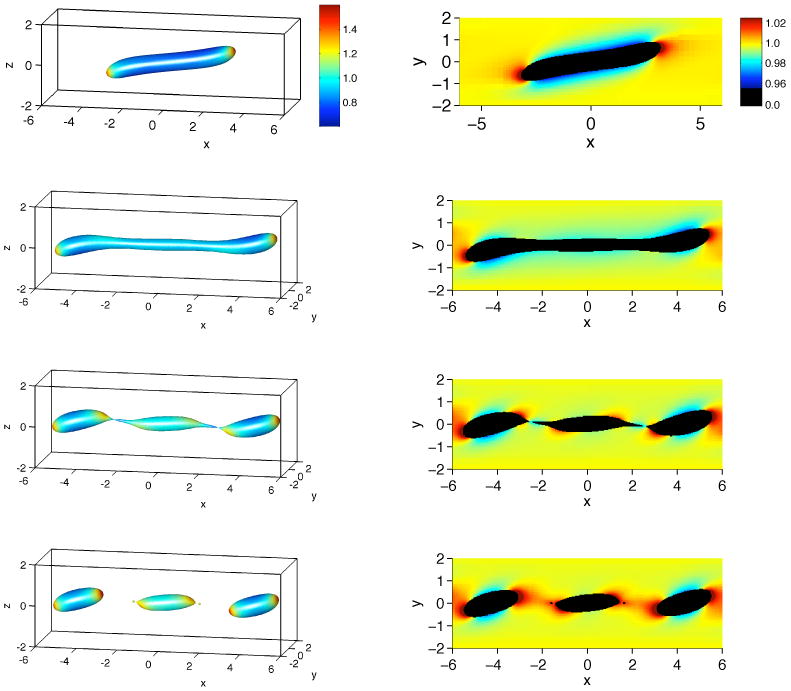
Three-dimensional simulation of a drop in shear flow with soluble surfactant, ε = 1/80. The left column shows the drop shape with the surface colored according to the interface surfactant concentration. The right column shows a slice of the bulk surfactant concentration along the x-axis. The times shown are from top to bottom: 10, 25, 34 and 35.16.
6. Conclusions and future work
A diffuse-interface method to simulate two-phase flows with soluble surfactants was presented. The method handles advection, diffusion and adsorption/desorption of surfactant, and is easy to implement using standard numerical techniques.
As an example of the applicability of the method, results were presented on the influence of solubility on a drop in shear flow. It was shown that solublity could have a considerable influence on the flow dynamics. Simulations in 3D were also performed, which showed that the influence of soluble surfactants is important for the breakup behavior of the drop.
Although not presented here, asymptotic and numerical evidence suggests that the convergence to the sharp interface system is first order in the interface thickness parameter ε [61]. It may be possible to gain second order accuracy in ε by explicitly removing the corresponding term in the asymptotic expansion as can be done in the context of solidification to enable simulations with arbitrary kinetic coefficients [80, 81]. Also, more consistent projection methods for collocated grids were recently presented in [82]. These two improvements to the proposed method should be explored. In addition, as we have seen, when the bulk Peclet number is large, thin boundary layers develop near the deforming drop. Adaptive meshes can enable accurate simulations for a range of Peclet numbers but in some applications, the bulk Peclet number can reach 105-106 (e.g., [83]) at which point it is infeasible to use adaptive meshes. Instead, following the approach recently developed by Booty & Siegel [23], a singular perturbation analysis should be incorporated in the numerical algorithm.
Acknowledgments
The authors thank Steven Wise and Fang Jin for assistance with the numerical code and visualization. KET is funded by the project “Electrocoalescence – Criteria for an efficient process in real crude oil systems”; coordinated by SINTEF Energy Research. The project is supported by The Research Council of Norway, under the contract no: 169466/S30, and by the following industrial partners: Aker Solutions AS, BP Exploration Operating Company Ltd, Hamworthy Technology & Products AS, Petrobras, Saudi Aramco, Shell Technology Norway AS and Statoil ASA. KET also acknowledges support from the Research Council of Norway through grant IS-BILAT 192532 and from the Fulbright Foundation. JL acknowledges support from the National Science Foundation Division of Mathematical Sciences (DMS) and from the National Institutes of Health through grant P50GM76516 for a Centre of Excellence in Systems Biology at the University of California, Irvine. AV acknowledges support from the German Science Foundation through grants Vo899/6-1 and SFB 609.
Footnotes
Publisher's Disclaimer: This is a PDF file of an unedited manuscript that has been accepted for publication. As a service to our customers we are providing this early version of the manuscript. The manuscript will undergo copyediting, typesetting, and review of the resulting proof before it is published in its final citable form. Please note that during the production process errors may be discovered which could affect the content, and all legal disclaimers that apply to the journal pertain.
References
- 1.Tryggvason G, Abdollahi-Alibeik J, Willmarth WW, Hirsa A. Collision of a vortex pair with a contaminated free surface. Phys Fluids A. 1992;4:1215–1229. [Google Scholar]
- 2.Matar OK, Troian SM. The development of transient fingering patterns during the spreading of surfactant coated films. Phys Fluids. 1999;11:3232–3246. [Google Scholar]
- 3.Leal LG. Flow induced coalescence of drops in a viscous fluid. Phys of Fluids. 2004;16(6):1833–1851. [Google Scholar]
- 4.Bazhlekov I, Anderson P, Meijer H. Numerical investigation of the effect of insoluble surfactants on drop deformation and breakup in simple shear flow. J Coll Int Sci. 2006;298:369–394. doi: 10.1016/j.jcis.2005.12.017. [DOI] [PubMed] [Google Scholar]
- 5.Hameed M, Siegel M, Young YN, Li J, Booty MR, Papageorgiou DT. Influence of insoluble surfactant on the deformation and breakup of a bubble or thread in a viscous fluid. J of Fluid Mech. 2008;594:307–340. [Google Scholar]
- 6.Bruijn RD. Tip sreaming of drops in simple shear flows. Chem Engng Sci. 1993;48:277–284. [Google Scholar]
- 7.Stone HA, Leal LG. The effect of surfactants on drop deformation and breakup. J Fluid Mech. 1990;220:161–186. [Google Scholar]
- 8.Milliken WJ, Stone HA, Leal LG. The effect of surfactant on transient motion of Newtonian drops. Phys Fluids A. 1993;5:69–79. [Google Scholar]
- 9.Li X, Pozrikidis C. The effect of surfactants on drop deformation and on the rheology of dilute emulsions in Stokes flow. J Fluid Mech. 1997;341:165–194. [Google Scholar]
- 10.Milliken WJ, Leal LG. The influence of surfactant on the deformation and breakup of a viscous drop - the effect of surfactant solubility. J Colloid and Interface Sci. 1994;166:275–285. [Google Scholar]
- 11.Pozrikidis C. Interfacial dynamics for Stokes flow. J Comput Phys. 2001;169:250–301. [Google Scholar]
- 12.Tryggvason G, Bunner B, Esmaeeli A, Juric D, Al-Rawahi N, Tauber W, Han J, Nas S, Jan YJ. Front tracking method for the computation of multiphase flow. J Comput Phys. 2001;169:708–759. [Google Scholar]
- 13.Jan YJ. PhD thesis. University of Michigan; 1994. Computational studies of bubble dynamics. [Google Scholar]
- 14.Zhang J, Eckmann D, Ayyaswamy P. A front tracking method for a deformable intravascular bubble in a tube with soluble surfactant transport. Journal of Computational Physics. 2006;214:366–396. [Google Scholar]
- 15.Muradoglu M, Tryggvason G. A front-tracking method for computation of interfacial flows with soluble surfactants. J Comput Phys. 2008;227:2238–2262. [Google Scholar]
- 16.Mittal R, Iaccarino G. Immersed boundary methods. Ann Rev Fluid Mech. 2005;37:239–361. [Google Scholar]
- 17.Lai MC, Tseng YH, Huang H. An immersed boundary method for interfacial flows with insoluble surfactant. J Comput Phys. 2008;227:7270–7293. [Google Scholar]
- 18.Tseng YH, Ferziger JH. A ghost-cell immersed boundary method for flow in complex geometry. J Comput Phys. 2003;192:593–623. [Google Scholar]
- 19.Jin F, Stebe KJ. The effects of a diffusion controlled surfactant on a viscous drop injected into a viscous medium. Phys Fluids. 2007;19:112103. [Google Scholar]
- 20.Ceniceros H. The effects of surfactants on the formation and evolution of capillary waves. Phys Fluids. 2003;15:245–256. [Google Scholar]
- 21.Liao YC, Franses E, Basaran O. Deformation and breakup of a stretching liquid bridge covered with an insoluble surfactant monolayer. Phys Fluids. 2006;18:022101. [Google Scholar]
- 22.Xu Q, Liao YC, Basaran O. Can surfactant be present at pinch-off of a liquid filament. Phys Rev Lett. 2007;98:054503. doi: 10.1103/PhysRevLett.98.054503. [DOI] [PubMed] [Google Scholar]
- 23.Booty M, Siegel M. A hybrid numerical method for interfacial fluid flow with soluble surfactant. J Comput Phys. 2010;229:3864–3883. [Google Scholar]
- 24.Scardovelli R, Zaleski S. Direct numerical simulation of free surface and interfacial flows. Ann Rev Fluid Mech. 1999;31:567–603. [Google Scholar]
- 25.Renardy YY, Renardy M, Cristini V. A new volume-of-fluid formulation for surfactants and simulations of drop deformation under shear at a low viscosity ratio. European Journal of Mechanics - B/Fluids. 2002;21:49–59. [Google Scholar]
- 26.James AJ, Lowengrub J. A surfactant-conserving volume-of-fluid method for interfacial flows with insoluble surfactant. Journal of Computational Physics. 2004;201:685–722. [Google Scholar]
- 27.Alke A, Bothe D. 3d numerical modelling of soluble surfactant at fluidic interfaces based on the volume-of-fluid method. FDMP. 2009;1:1–29. [Google Scholar]
- 28.Osher S, Sethian J. Fronts propagating with curvature-dependent speed– algorithms based on Hamilton-Jacobi formulations. J Comput Phys. 1988;79:12–49. [Google Scholar]
- 29.Xu JJ, Zhao H. An Eulerian formulation for solving partial differential equations along a moving interface. J Sci Comp. 2003;19:573–594. [Google Scholar]
- 30.Xu JJ, Li Z, Lowengrub J, Zhao H. A level set method for interfacial flows with surfactant. J Comp Phys. 2006;212:590–616. [Google Scholar]
- 31.Sethian J, Smereka P. Level-set methods for fluid interfaces. Ann Rev Fluid Mech. 2003;35:341–372. [Google Scholar]
- 32.Yang X, James AJ. An arbitrary Lagrangian-Eulerian (ALE) method for interfacial flows with insoluble surfactants. FDMP. 2007;3:65–96. [Google Scholar]
- 33.Young YN, Booty MR, Siegel M, Li J. Influence of surfactant solubility on the deformation and breakup of a bubble or capillary jet in a viscous fluid. Phys Fluids. 2009;21:072105. [Google Scholar]
- 34.Uzgoren E, Sim J, Shyy W. Marker-based, 3d adaptive Cartesian grid method for multiphase flow around irregular geometries. Comm Comput Phys. 2009;5:1–41. [Google Scholar]
- 35.Adami S, Hu X, Adams N. A conservative SPH method for surfactant dynamics. J Comput Phys [Google Scholar]
- 36.Anderson DM, McFadden GB, Wheeler AA. Diffuse interface methods in fluid mechanics. Ann Rev Fluid Mech. 1998;30(1):139–165. [Google Scholar]
- 37.Emmerich H. Advances of and by phase-field modeling in condensed-matter physics. Adv Phys. 2008;57:1–87. [Google Scholar]
- 38.Lowengrub J, Truskinovsky L. Quasi-incompressible Cahn-Hilliard fluids and topological transitions. R Soc Lond Proc Ser A Math Phys Eng Sci. 1998;454:2617–2654. [Google Scholar]
- 39.Jacqmin D. Calculation of two-phase Navier-Stokes flows using phase-field modeling. J Comput Phys. 1999;155:96–127. [Google Scholar]
- 40.Lee H, Lowengrub J, Goodman J. Modeling pinchoff and reconnection in a Hele–Shaw cell i. the models and their calibration. Phys Fluids. 2002;14:492–513. [Google Scholar]
- 41.Lee H, Lowengrub J, Goodman J. Modeling pinchoff and reconnection in a hele-shaw cell ii. analysis and simulation in the nonlinear regime. Phys Fluids. 2002;14:514–545. [Google Scholar]
- 42.Baldalassi V, Ceniceros H, Banerjee S. Computation of multiphase systems with phase field models. J Comput Phys. 2004;190:371–397. [Google Scholar]
- 43.Boyer F, Chupin L, Franck B. Numerical study of viscoelastic mixtures through a Cahn–Hilliard model. Eur J Mech B-Fluids. 2004;23:759–780. [Google Scholar]
- 44.Yue P, Feng JJ, Liu C, Shen J. A diffuse interface method for simulating two phase flows of complex fluids. J Fluid Mech. 2004;515:293–317. [Google Scholar]
- 45.Kim J. A continuous surface tension force formulation for diffuse-interface models. Journal of Computational Physics. 2005;204(2):784–804. [Google Scholar]
- 46.Lu HW, Glasner K, Bertozzi A, Kim CJ. A diffuse interface model for electrowetting droplets in a Hele-Shaw cell. J Fluid Mech. 2007;590:411–435. [Google Scholar]
- 47.Ding H, Spelt P, Shu C. Diffuse interface model for incompressible two-phase flows with large density ratios. J Comput Phys. 2007;226:2078–2095. [Google Scholar]
- 48.van der Sman R, van der Graaf S. Diffuse interface model of surfactant adsorption onto flat and droplet interfaces. Rheol Acta. 2006;46:3–11. [Google Scholar]
- 49.Jacqmin D. Contact-line dynamics of a diffuse interface. J Fluid Mech. 2000;402:57–88. [Google Scholar]
- 50.Do-Quang M, Amberg G. The splash of a solid sphere impacting on a liquid surface: Numerical simulation of the influence of wetting. Phys Fluids. 2009;21:022102. [Google Scholar]
- 51.Aland S, Lowengrub J, Voigt A. Two-phase flow in complex geometries: A diffuse domain approach, in preparation. 2009 [PMC free article] [PubMed] [Google Scholar]
- 52.Rätz A, Voigt A. PDEs on surfaces—a diffuse interface approach. Commun Math Sci. 2006;4:575–590. [Google Scholar]
- 53.Rätz A, Voigt A. A diffuse-interface approximation for surface diffusion including adatoms. Nonlinearity. 2007;20:177–192. [Google Scholar]
- 54.Dziuk G, Elliott C. Eulerian finite element method for parabolic PDEs on complex surfaces. Int Free Bound. 2008;10:119–138. [Google Scholar]
- 55.Lowengrub J, Rätz A, Voigt A. Phase-field modeling of the dynamics of multicomponent vesicles: Spinodal decomposition, coarsening, budding and fission. Phys Rev E. 2008;79:031926. doi: 10.1103/PhysRevE.79.031926. [DOI] [PMC free article] [PubMed] [Google Scholar]
- 56.Elliott C, Stinner B. Analysis of a diffuse interface approach to an advection diffusion equation on a moving surface. Math Mod Meth Appl Sci. 2009 in press. [Google Scholar]
- 57.Kockelkoren J, Levine H, Rappel WJ. Computational approach for modeling intra- and extracellular dynamics. Phys Rev E. 2003;68(3):037702. doi: 10.1103/PhysRevE.68.037702. [DOI] [PubMed] [Google Scholar]
- 58.Levine H, Rappel WJ. Membrane-bound Turing patterns. Phys Rev E. 2005;72(6):061912. doi: 10.1103/PhysRevE.72.061912. [DOI] [PubMed] [Google Scholar]
- 59.Fenton F, Cherry E, Karma A, Rappel WJ. Modeling wave propagation in realistic heart geometries using the phase-field method. Chaos. 2005;15:103502. doi: 10.1063/1.1840311. [DOI] [PubMed] [Google Scholar]
- 60.Li X, Lowengrub J, Rätz A, Voigt A. Solving PDEs in complex geometries: A diffuse domain approach. Commun Math Sci. 2009;7:81–107. doi: 10.4310/cms.2009.v7.n1.a4. [DOI] [PMC free article] [PubMed] [Google Scholar]
- 61.Teigen KE, Wang F, Li X, Lowengrub J, Voigt A. A diffuse-interface approach for modelling transport, diffusion and adsorption/desorption of material quantities on a deformable interface. Commun Math Sci. 2009;7:1009–1037. doi: 10.4310/cms.2009.v7.n4.a10. [DOI] [PMC free article] [PubMed] [Google Scholar]
- 62.Lee HG, Lowengrub J, Goodman J. Modeling pinchoff and reconnection in a hele-shaw cell i: The models and their calibration. Phys Fluids. 2002;14:492–513. [Google Scholar]
- 63.Lee HG, Lowengrub J, Goodman J. Modeling pinchoff and reconnection in a hele-shaw cell ii: Analysis and simulation in the nonlinear regime. Phys Fluids. 2002;14:514–545. [Google Scholar]
- 64.Stone HA. The dynamics of drop deformation and breakup in viscous fluids. Ann Rev Fluid Mech. 1994;26:65–102. [Google Scholar]
- 65.Sheth KS, Pozrikidis C. Effects of inertia on the deformation of liquid drops in simple shear flow. Comput & Fluids. 1995;24(2):101–119. [Google Scholar]
- 66.Li J, Renardy YY, Renardy M. Numerical simulation of breakup of a viscous drop in simple shear flow through a volume-of-fluid method. Phys Fluids. 2000;12:269–282. [Google Scholar]
- 67.Cristini V, Blawzdziewicz J, Loewenberg M. An adaptive mesh algorithm for evolving surfaces: Simulation of breakup and coalescence. J Comput Phys. 2001;168:445–463. [Google Scholar]
- 68.Velankar S, Zhou H, Jeon H, Macosko C. CFD evaluation of drop retraction methods for the measurement of interfacial tension of surfactant-laden drops. J Colloid Interface Sci. 2004;272(1):172–185. doi: 10.1016/j.jcis.2003.09.030. [DOI] [PubMed] [Google Scholar]
- 69.Eggleton CD, Pawar YP, Stebe KJ. Insoluble surfactants on a drop in an extensional flow: a generalization of the stagnated surface limit to deforming interfaces. J of Fluid Mech. 1999;385:79–99. [Google Scholar]
- 70.Wong H, Rumschitzki D, Maldarelli C. On the surfactant mass balance at a deforming fluid interface. Phys Fluids. 1996;8:3203–3204. [Google Scholar]
- 71.Wise S, Kim J, Lowengrub J. Solving the regularized, strongly anisotropic Cahn-Hilliard equation by an adaptive nonlinear multigrid method. J Comput Phys. 2007;226:414–446. [Google Scholar]
- 72.Shu CW, Osher S. Efficient implementation of essentially non-oscillatory shock-capturing schemes. J Comput Phys. 1988;77(2):439–471. [Google Scholar]
- 73.Liu S, Chan T. Weighted essentially non-oscillatory schemes. J Comput Phys. 1994;115:200–212. [Google Scholar]
- 74.Bell JB, Colella P, Glaz HM. A second-order projection method for the incompressible navier-stokes equations. J Comput Phys. 1989;85(2):257–283. [Google Scholar]
- 75.Kim J, Kand K, Lowengrub J. Conservative multigrid methods for ternary Cahn-Hilliard fluids. J Comput Phys. 2004;193:511–543. [Google Scholar]
- 76.Sussman M, Almgren AS, Bell JB, Colella P, Howell LH, Welcome ML. An adaptive level set approach for incompressible two-phase flows. Journal of Computational Physics. 1999;148(1):81–124. [Google Scholar]
- 77.Lorensen WE, Cline HE. Marching cubes: A high resolution 3D surface construction algorithm. Computer Graphics. 1987;21:163–169. [Google Scholar]
- 78.Prosperetti A. Motion of two superposed viscous fluids. Phys Fluids. 1981;24:1217–1223. [Google Scholar]
- 79.Young NO, Goldstein JS, Block MJ. The motion of bubbles in a vertical temperature gradient. J of Fluid Mech. 1959;6(03):350–356. [Google Scholar]
- 80.Karma A, Rappel WJ. Phase-field method for computationally efficient modeling of solidification with arbitrary interface kinetics. Phys Rev E. 1996;53(4):R3017–R3020. doi: 10.1103/physreve.53.r3017. [DOI] [PubMed] [Google Scholar]
- 81.Karma A, Rappel WJ. Quantitative phase-field modeling of dendritic growth in two and three dimensions. Phys Rev E. 1998;57(4):4323–4349. doi: 10.1103/PhysRevE.57.4323. [DOI] [Google Scholar]
- 82.Ni MJ. Consistent projection methods for variable density incompressible Navier-Stokes equations with continuous surface forces on a rectangular collocated mesh. J Comput Phys. Accepted. [Google Scholar]
- 83.Chang C, Franses E. Adsorption dynamics of surfactants at the air/water interface: A critical review of mathematical models, data, and mechanisms. Colloids Surfaces A. 1995;100:1–45. [Google Scholar]


