

Abstract
FastSPECT III is a stationary, single-photon emission computed tomography (SPECT) imager designed specifically for imaging and studying neurological pathologies in rodent brain, including Alzheimer’s and Parkinsons’s disease. Twenty independent BazookaSPECT [1] gamma-ray detectors acquire projections of a spherical field of view with pinholes selected for desired resolution and sensitivity. Each BazookaSPECT detector comprises a columnar CsI(Tl) scintillator, image-intensifier, optical lens, and fast-frame-rate CCD camera. Data stream back to processing computers via firewire interfaces, and heavy use of graphics processing units (GPUs) ensures that each frame of data is processed in real time to extract the images of individual gamma-ray events. Details of the system design, imaging aperture fabrication methods, and preliminary projection images are presented.
I. Introduction
The advantages of stationary and dynamic SPECT systems, in which all projections required for tomographic reconstruction are acquired in parallel, have been demonstrated in a series of instruments developed at the Center for Gamma-ray Imaging (CGRI) [2]–[4]. The latest member of this family of stationary SPECT imagers is FastSPECT III, a dedicated rodent brain imager. High-resolution SPECT imaging of the mouse/rat brain is of great interest for studying neurological pathologies, including Alzheimer’s and Parkinson’s disease. Many such studies have not been possible in the past due to the resolution limitations of current SPECT imagers. FastSPECT III addresses resolution limitations by providing initial SPECT reconstructions with isotropic linear resolutions ~ 250 μm. Additionally, it provides the capability for dynamic imaging studies.
FastSPECT III is built around a new class of scintillation-based gamma-ray detector technology developed at CGRI called BazookaSPECT [1], [5], [6]. BazookaSPECT gamma cameras are the combination of a scintillation crystal, an integrating detector such as a CCD/CMOS sensor, and a microchannel plate (MCP)-based image intensifier. The result is a high-resolution, gamma-ray detector capable of operation at high counting rates; <100 μm intrinsic detector resolution and counting rates > 107 counts per second have been achieved [1], [6].
In BazookaSPECT detectors, a scintillator/gamma-ray interaction results in the production of many optical photons. These optical photons are amplified by an image intensifier which provides a luminous gain ~ 104–106, depending on the number of MCPs. The output screen of the intensifier is imaged onto a CCD/CMOS sensor and scintillation light is seen as a cluster of signal spread over multiple pixels, e.g. a diameter of 10 pixels. Clusters are extracted and processed in real-time on an event-by-event basis; a process called frame parsing [6]. Figure 1 shows a CCD frame taken with a BazookaSPECT detector and the corresponding interaction position estimates.
Fig. 1.

(a) Data frame from a BazookaSPECT detector where bright flashes correspond to scintillation light from individual gamma-ray interactions. (b) Position estimates of gamma-ray interactions which are calculated by either centroiding or maximum-likelihood estimation techniques.
In this paper we discuss the system integration of FastSPECT III and the technological advances it has spurred. These include the development of compact BazookaSPECT modules, development of a novel fabrication method for producing custom imaging apertures and pinholes using 3D rapid prototyping printers, and the use of graphics processing units (GPUs) and multi-core processors to achieve real-time event detection and position and energy estimation at high counting rates. Additionally, we present the first set of pinhole projection images acquired with the system.
II. Compact Detectors for FastSPECT III
The original BazookaSPECT detector, shown in Figure 2a, is over half-a-meter in length due to a long imaging chain. Two lenses, combined in a macro-configuration where magnification is given as a ratio of the focal lengths, image the output screen of the image intensifier onto the CCD sensor [1]. The detector’s resemblance to a Bazooka gave rise to its name, and the name BazookaSPECT has persisted even when the device is much shorter and is not used for SPECT imaging.
Fig. 2.

(a) Original prototype BazookaSPECT detector, (b) FastSPECT III BazookaSPECT detector comprising a columnar CsI(Tl) scintillator fabricated by RMD, a 50-mm diameter image intensifier, spacer rings, 6 mm F/1.2 C-mount lens, and a 640 × 480 CCD camera which operates up to 200 frames per second at full resolution.
During the design phase of the supporting structure for FastSPECT III, it was realized that a compact BazookaSPECT module would ease design requirements and allow for the construction of a highly compact SPECT imager. Additionally, it would reduce overall cost of the system. Shown in Figure 2, we have reduced the overall length of the detector by more than factor of 2× compared to the original prototype detector. This is achieved by replacing the two-lens, macro-configuration with a single, short-focal-length lens [6] and spacer rings.
The FastSPECT III, BazookaSPECT detector shown in Figure 2b comprise a 50-mm diameter image intensifier, a 640 × 480 CCD which operates up to 200 frames per second at full resolution, a 450-μm thick, 50-mm diameter columnar CsI(Tl) scintillator fabricated by Radiation Monitoring Devices, Inc. (RMD), and a 6-mm F/1.2 C-mount lens. In this configuration, the effective pixel size of the detector is ~ 104 μm.
For rodent brain imaging, the FastSPECT III frame is designed so that each detector is focused around a common, spherical field of view. The frame supports twenty, compact BazookaSPECT modules arranged in three rings: a central ring which supports ten detectors, and two outer rings which each support five angled detectors. Images of the frame with cameras installed are shown in Figure 3.
Fig. 3.
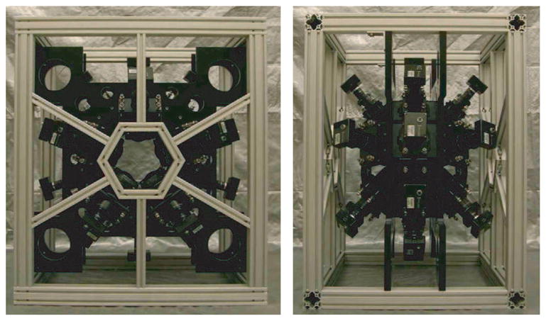
Front and side views of the FastSPECT III imaging system. A central ring of ten and two outer rings of five BazookaSPECT detectors focus at common field of view.
III. Novel Aperture and Pinhole Fabrication using Rapid Prototyping
The imaging aperture of a stationary SPECT system, designed for isotopes in the range of 20–200 keV, typically consists of pinhole inserts made from high-density materials such as platinum, gold, or tungsten. To provide shielding and to reduce scattered or background events, the supporting aperture structure is also made from a high-density material such as lead or tungsten. With complex camera geometries, the imaging aperture design and fabrication becomes expensive and difficult using traditional machining techniques.
As previously discussed, all twenty BazookaSPECT detectors in FastSPECT III share a common field of view. With this arrangement of cameras, specifically the ten angled detectors, we were presented with a challenge for cost-effectively fabricating the pinhole imaging aperture. This spurred the development a novel method for designing and fabricating apertures specific to the imaging task and independent of the geometric complexity of the stationary SPECT system. Briefly, this method involves designing an aperture part in a 3D modeling program, e.g. Solidworks® [?], printing the part or mold on a 3D rapid prototyping printer, and then casting the final part either using lost-wax or cold casting methods. The reader is referred to [7] for more details and examples.
To fabricate the supporting aperture structure, we worked with Tungsten Heavy Powder, Inc. [8] to create parts made of a tungsten composite material. This process involves printing a mold of the part and then cold-casting with a high-density tungsten powder/epoxy mixture. After the mixture is cured, the part is removed yielding a tungsten-composite part having a density near that of lead ~ 11 g/cm3. An additional advantage of this process is that multiple parts can be fabricated from a single mold.
For pinhole fabrication, the 3D model of the pinhole insert is printed and then cast in platinum using investment or lost-wax casting methods. Pinhole inserts for FastSPECT III were cast in platinum by Techform Advanced Casting [9] successfully down to 200 μm. Initial studies with FastSPECT III will utilize 500 μm and 200 μm single-pinhole apertures with BazookaSPECT detectors sharing a common field of view of ~ 15 mm. The geometrical resolution of projection images from these apertures is ~ 650 and ~ 265 μm, respectively. Images of the pinholes, the aperture assembly, and the complete imaging aperture installed in the FastSPECT III frame are shown in Figure 4.
Fig. 4.
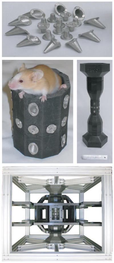
FastSPECT III imaging aperture fabricated using 3D rapid-prototyping printers and casting techniques. Top: platinum pinhole inserts made by lost-wax casting methods; Middle: (left) cold-cast tungsten composite aperture with pinhole inserts, (right) complete imaging aperture; Bottom: imaging aperture installed in FastSPECT III frame.
IV. FastSPECT III: Real-Time Data acquisition and Processing Using GPUs and Multi-Core Processors
Recent advances in graphics processing hardware, with devices having hundreds of stream processors, allow for high-speed parallel computing in many medial imaging applications. FastSPECT III makes heavy use of graphics processing units (GPUs) to achieve real-time event detection and position estimation at high counting rates.
In BazookaSPECT detectors, when the cluster size is small in comparison to the CCD/CMOS sensor, and the number of events per frame is small such that there is minimal overlap, individual gamma-ray/x-ray events can be identified and their associated pixel regions extracted. We refer to this process as frame parsing [6]. One algorithm for frame processing uses the following steps:
A frame from the CCD is acquired.
A median filter is applied to remove hot/noisy pixels.
The filtered image is thresholded above the noise, and individual clusters are identified via a fast connected components labeling algorithm [10].
Pixels corresponding to the identified clusters are extracted (e.g. 3 × 3 to 11 × 11 region of pixels).
Using the associated cluster pixels, the 2D/3D interaction location is estimated optimally using maximum-likelihood (ML) estimation [11].
A visual demonstration of this algorithm is shown in Figure 5. FastSPECT III computers implement this algorithm in real-time with the use of graphics processing units (GPUs) and multi-core processors. For each gamma-ray interaction, a super listmode [11] entry is created which contains a time stamp and pixel data associated with the event.
Fig. 5.

Data acquisition and processing algorithm (zoomed region contains five gamma-ray interaction clusters): (a) Acquired photon-counting image (raw data), (b) noisy pixels removed using a median-filter, (c) filtered image with individual clusters identified using a connected components labeling algorithm [10] (cluster regions identified by color), and (d) the estimated 2D γ-ray interaction positions. The position estimate, time stamp, summed pixels values, and all associated cluster pixels are concatenated and written to disk as a listmode [11] event entry.
The FastSPECT III data acquisition/processing system consists of six computers. Five computers, each with four BazookaSPECT detectors connected, acquire and frame parse image data. Super listmode data are streamed to a dedicated sixth computer which performs a real-time MLEM tomographic reconstruction.
The CCD detectors are PointGrey Research, Inc. [12] DragonFly Express cameras which stream images to firewire (1394b) frame grabbers at a rate of up to 800 Mbps or at 200 frames per second (fps) at full resolution (640 × 480). The firewire bus is daisy chained across computers to synchronize cameras for timing purposes in dynamic imaging studies. Each computer has an Intel® Core™; i7 quad-core processor and two Nvidia® GeForce® GTX 295 cards. There are two GPUs per GTX 295 card providing a total of 960 stream processors per computer. Frame parsing with multiple detectors at 200 fps is readily achieved by parallel computing using Nvidia CUDA [13] and OpenMP [14] APIs. Operation of the detectors at this rate corresponds to processing 4,000 fps for the entire system or 1.23 Gpix/second. Assuming uniform illumination, more than 2.5 × 10⁴ counts per second per detector or > 5 × 10⁵ for the entire system can be processed. The FastSPECT III acquisistion/processing system is shown in Figure 6.
Fig. 6.

Complete FastSPECT III imaging system with acquisition/processing computers. CCD data from all cameras are acquired and processed simultaneously.
V. Results
With the computer acquisition/processing system and pinhole imaging aperture installed, we acquired the first preliminary pinhole projection images using an 125I brachytherapy seed. The projection images from all twenty cameras are shown in Figure 7.
Fig. 7.

FastSPECT III preliminary projection images of a 125I bracytheraphy seed having an activity of 793 μCi. Acquisition time was 300 seconds and projection images were acquired using 0.5 mm diameter pinholes.
VI. Conclusion
FastSPECT III represents the first stationary SPECT imager based on BazookaSPECT detector technology. System integration is complete with the imaging aperture installed and with all twenty BazookaSPECT detectors acquiring and processing data in parallel at rates up to 200 frames per second. Remaining tasks before imaging studies begin include measurement of the system H matrix and implementation of real-time MLEM tomographic reconstructions on GPUs.
It is anticipated that FastSPECT III will make a significant impact and contribution to small-animal SPECT imaging as a dedicated rodent brain imager. Additionally, the system will serve as a test bed for adaptive imaging studies [15]–[17] and and evaluation of various scintillation crystals. In summary, FastSPECT III represents the melding of a cost-effective and compact gamma camera design, high-speed data acquisition and processing techniques using graphics hardware, and innovation in aperture/pinhole fabrication techniques.
Acknowledgments
This work was supported by the National Institutes of Health under NIBIB Grant P41-EB002035 (Center for Gamma-ray Imaging), NIH grant R37-EB000803, and the Arizona Alzheimer’s Consortium.
This work is supported by The Center for Gamma-Ray Imaging under NIBIB grant P41-EB002035, NIH grant R37-EB000803, and the Arizona Alzheimer’s Consortium. The authors would like to thank Dr. Michael Gehm and Wei Ren Ng at the Laboratory for Engineering Non-Traditional Sensors (LENS), University of Arizona, for use of their Objet Eden350™ rapid prototyping printer in aperture/pinhole development and fabrication.
Contributor Information
Brian W. Miller, College of Optical Sciences, University of Arizona, Tucson, AZ 85724 USA.
Lars R. Furenlid, Department of Radiology Research and College of Optical Sciences, University of Arizona, Tucson, AZ 85724 USA.
Stephen K. Moore, Department of Biomedical Engineering, University of Arizona, Tucson, AZ 85724 USA.
H. Bradford Barber, Department of Radiology Research and College of Optical Sciences, University of Arizona, Tucson, AZ 85724 USA.
Vivek V. Nagarkar, Radiation Monitoring Devices (RMD), Inc., Watertown, MA 02472 USA
Harrison H. Barrett, Department of Radiology Research and College of Optical Sciences, University of Arizona, Tucson, AZ 85724 USA.
References
- 1.Miller B, Barber H, Barrett H, Wilson D, Chen L. A Low-Cost Approach to High-Resolution, Single-Photon Imaging Using Columnar Scintillators and Image Intensifiers. 6:3540–3545. 29 2006-Nov. 1 2006. [Google Scholar]
- 2.Klein W, Barrett H, Pang I, Patton D, Rogulski M, Sain J, Smith W. FASTSPECT: electrical and mechanical design of a high-resolution dynamic SPECT imager. Nuclear Science Symposium and Medical Imaging Conference Record, 1995., 1995 IEEE; Oct 1995; pp. 931–933. [Google Scholar]
- 3.Furenlid L, Wilson D, chun Chen Y, Kim H, Pietraski P, Crawford M, Barrett H. FastSPECT II: a second-generation high-resolution dynamic SPECT imager. Nuclear Science, IEEE Transactions. 2004 June;51(3):631–635. doi: 10.1109/TNS.2004.830975. [DOI] [PMC free article] [PubMed] [Google Scholar]
- 4.Kim H, Furenlid LR, Crawford MJ, Wilson DW, Barber HB, Peterson TE, Hunter WCJ, Liu Z, Woolfenden JM, Barrett HH. SemiSPECT: A small-animal single-photon emission computed tomography (SPECT) imager based on eight cadmium zinc telluride (CZT) detector arrays. Medical Physics. 2006;33(2):465–474. doi: 10.1118/1.2164070. [Online]. Available: http://link.aip.org/link/?MPH/33/465/1. [DOI] [PMC free article] [PubMed]
- 5.Miller B, Barrett H, Furenlid L, Bradford Barber H, Hunter R. Recent advances in BazookaSPECT: Real-time data processing and the development of a gamma-ray microscope. Nuclear Inst and Methods in Physics Research, A. 2008;591(1):272–275. doi: 10.1016/j.nima.2008.03.072. [DOI] [PMC free article] [PubMed] [Google Scholar]
- 6.Miller BW, Barber HB, Furenlid LR, Moore SK, Barrett HH. Doty FP, Barber HB, Roehrig H, Schirato RC, editors. Progress of BazookaSPECT. SPIE. 2009;7450(1):74500C. doi: 10.1117/12.843742. [Online]. Available: http://link.aip.org/link/?PSI/7450/74500C/1. [DOI] [PMC free article] [PubMed]
- 7.Miller B, Moore J, Gehm M, Furenlid L, Barrett H. Novel Applications of Rapid Prototyping in Gamma-ray and X-ray Imaging. IEEE Nuclear Science Symposium Conference Record, 2009. NSS’09; 2009. [DOI] [PMC free article] [PubMed] [Google Scholar]
- 8.Tungsten Heavy Powder, Inc. (THP) [Online]. Available: http://www.tungstenheavypowder.com/
- 9.Techform Advanced Casting Technology. [Online]. Available: http://www.techformcasting.com/
- 10.Suzuki K, Horiba I, Sugie N. Fast connected-component labeling based on sequential local operations in the course of forward raster scan followed by backward raster scan. 2000;2:434–437. [Google Scholar]
- 11.Barrett H, Hunter W, Miller B, Moore S, Chen Y, Furenlid L. Maximum-likelihood methods for processing signals from gamma-ray detectors. Nuclear Science, IEEE Transactions. 2009 June;56(3):725–735. doi: 10.1109/tns.2009.2015308. [DOI] [PMC free article] [PubMed] [Google Scholar]
- 12.Point Grey Research, Inc. [Online]. Available: http://www.ptgrey.com/
- 13.NVIDIA, CUDA. Compute Unified Device Architecture-Programming Guide Version 2.0. 2009. [Google Scholar]
- 14.Dagum L, Menon R. Open MP: An Industry-Standard API for Shared-Memory Programming. IEEE Computational Science and Engineering. 1998;5(1):46–55. [Google Scholar]
- 15.Freed M, Kupinski MA, Furenlid LR, Wilson DW, Barrett HH. A prototype instrument for single pinhole small animal adaptive SPECT imaging. Medical Physics. 2008;35(5):1912–1925. doi: 10.1118/1.2896072. [Online]. Available: http://link.aip.org/link/?MPH/35/1912/1. [DOI] [PMC free article] [PubMed]
- 16.Barrett H, Furenlid L, Freed M, Hesterman J, Kupinski M, Clarkson E, Whitaker M. Adaptive SPECT. Medical Imaging, IEEE Transactions. 2008 June;27(6):775–788. doi: 10.1109/TMI.2007.913241. [DOI] [PMC free article] [PubMed] [Google Scholar]
- 17.Clarkson E, Kupinski M, Barrett H, Furenlid L. A task-based approach to adaptive and multimodality imaging. Proceedings of the IEEE. 2008 March;96(3):500–511. doi: 10.1109/JPROC.2007.913553. [DOI] [PMC free article] [PubMed] [Google Scholar]