Abstract
Lensless on-chip imaging is a promising technique to count and monitor cells and micro-objects in liquid sample. In this paper we apply this technique to the observation of µL sample containing bacteria evaporated onto a microscope slide. Compared with previously reported techniques, a large improvement in signal to noise ratio is obtained due to the presence of a few μm thick wetting film creating a micro-lens on top of each bacteria. In these conditions, standard CMOS sensor are able to detect micro-objects as small as few μm, e.g. E.coli and Bacillus subtilis bacteria and 1 μm polymer beads with a large signal to noise ratio of 45 ± 10. An overall detection efficiency of 85 ± 7% and a co-localization error of σ1D = 1.1μm compared with reference fluorescence microscopy images are achieved. This novel technique will be used as a pre-positioning tool prior to other optical identification methods, e.g. Raman spectroscopy.
OCIS codes: (110.2970) Image detection systems, (170.3880) Medical and biological imaging
1. Introduction
Recent studies have demonstrated the ability of Raman spectroscopy and FT-IR spectroscopy [1,2] to detect and identify single bacteria within heterogeneous mixture [3,4]. However, these techniques require a careful positioning of the illumination beam onto the bacteria within 1 to 3 µm, which can hardly be achieved in sample volume of few ml with low concentration of analytes (102 to 103 bacteria/ml). Hence rapid, automated systems for detecting and identifying single bacteria in real-world ml samples requires the integration of sample processing steps, namely a pathogen concentration step and a pre-localization step prior to spectroscopic measurements [5]. We propose a solution based on two modules in line. The first module concentrates the pathogens to be analysed (microbes, bacteria, spores) from ml to µl by means of e.g. centrifugation, evaporates the solution on a microscope slide and provides the identification module with the pre-localization of the pathogens. The identification module can then scan the objects of interest and not the overall sample, reducing drastically the total analyses duration and presumably increasing measurement sensitivity.
This paper focuses on the second step of the sample preparation, namely the detection and localization of µm-size objects, e.g. bacteria and 1µm beads, in a few μL samples. We first describe a new lensless imaging technique. Micro-objects are revealed by liquid micro-lenses created during the sample evaporation that focalise the incident light onto the sensor. We assess this new technique in terms of detection efficiency and co-localization error in comparison with fluorescence microscopy images.
2. Thin wetting film lensless imaging system
Setup
Our system is based on the lensless imaging described by Ozcan et al. [6–8] that we modified so to perform controlled sample evaporation on top of a glass cover slip. As illustrated in Fig. 1 , it consists in an 1.7 W LED emitting at 555nm (Luxeon® K1Luxeon III), a glass cover slip (70x25x0.15 mm3) and a standard 8-bit 800x600 CMOS image sensor taken out of a Web camera V-Gear TalkCam 2000. The camera pixel size is 3µm and the field of view (FOV) is 2.4x1.8 = 4.3 mm2. The protective cap of the sensor has been removed in order to place the glass cover slip and the sample as close as possible to the sensor (<250μm). A typical experiment consists in depositing a droplet of 1μL containing bacteria on top of the cover slip, right above the CMOS sensor and let it evaporate for 2 minutes. The evaporation is controlled in order to obtain a thin wetting film of a few µm thick and a few mm in diameter on the surface of the glass cover slip. The LED, 10 cm above, illuminates the thin wetting film that contains the bacteria and an image is formed in transmission onto the sensor.
Fig. 1.
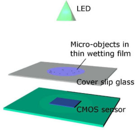
Schematic of the thin wetting film lensless imaging setup (not to scale).
Measurements
With this novel experimental setup, we observed that the signal amplitude of imaged bacteria is strongly related to the thickness of the liquid surrounding the bacteria, whether the bacteria is found in a droplet, in the meniscus of the droplet or in a thin wetting film. Figure 2(a) shows the image recorded from an E.coli in a 1µL droplet. A 100µm pinhole was added here in front of the LED in order to increase the spatial coherence of the illumination and thus increase the pattern visibility. The shadow pattern corresponds to a holographic diffraction pattern as described in [7]. A Signal to Noise Ratio (SNR) can be define for this pattern as , where I is the image amplitude, μ and σ are the mean and standard deviation of I in a background noise region. On the very few obtained detection (<<1%) the measured SNR of ~2 is definitely poor [Fig. 2(a)]. With few µm sized micro-objects such as E.coli bacteria in a droplet the occurrence of light scattering is weak and detecting bacteria with a standard CMOS is difficult.
Fig. 2.

Intensity profiles and image of E.coli bacteria detected in (a) a 1µl droplet using a 100µm pinhole and in (b) a thin wetting film (without pinhole). On the intensity profiles, the blue bold line corresponds to the mean value. The green bold line in (a) is the calculated intensity profile of a holographic pattern. Amplitude and mean value of the calculated profile are normalised with the measurements.
Figure 2(b) shows the image of E.coli created by a thin wetting film (without pinhole). The pattern shape changes to become non-symmetrical and more important the SNR increases up to 45 ± 10 (maximum of 65). The large increase in SNR can be explained by the formation of a liquid micro-lens on top of each bacteria and focusing the light onto the sensor. The bacteria may change the surface geometry of the thin wetting film and creates a plano-convex micro-lens. Figure 3 shows images of a 1µm polymer beads (Duke Scientific Corp. G0100) in a thin wetting film obtained with a transmission microscope (Olympus Provis AX70 x20 magnification) along the Z-axis. These measurements indicate also the presence a micro-lens focalising at a distance of ~25µm [9]. Transmission microscopy confirms that light focalisation occurs only in the presence of a thin wetting film [Figs. 3(a) and 3(b)]. On all the patterns obtained with lensless imaging, one can notice that the shadow ring is systematically more pronounced at the bottom right [Figs. 2(b) and 4 –6 ], while this is not observed on transmission microscopy images. This asymmetry does not depends on the geometry of the setup, is not modified whether one rotate or move either the glass cover slip or the LED. The only explanation we thought of is the dependency of the CMOS aperture on the incident light angle. This can be explained by the underlying asymmetry of the sub-pixel, i.e. the presence of a ‘dead’ readout region in one of the corner of every pixel.
Fig. 3.
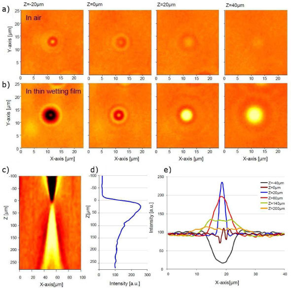
Image of 1μm diameter beads obtained with a x20/0.45NA transmission microscope (Olympus Provis AX70) as a function of the focal depth Z (front focus measurement, Z = 0 corresponds to the object plane). (a) In air after complete droplet evaporation. (b, c, d and e) In the presence of a thin wetting film. (c) XZ section through the middle of the bead image, (d) Z-axis maximum intensity profiles and (e) X-axis Intensity profile as a function of Z.
Fig. 4.
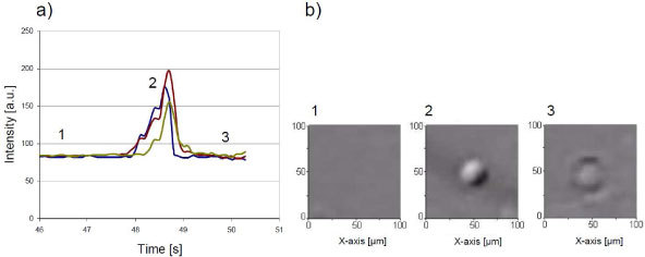
Temporary micro-lens effect. (a) Timecourse of the intensity and (b) images of E.coli bacteria during a complete evaporation of a 1µL droplet. The bacteria, at first undetectable (1), is revealed when in the meniscus (2) and disappears back when evaporation is complete (3). The three graphs represent three independent trials. The cover glass is here slightly hydrophobic, no thin wetting film remains after the evaporation.
Fig. 6.
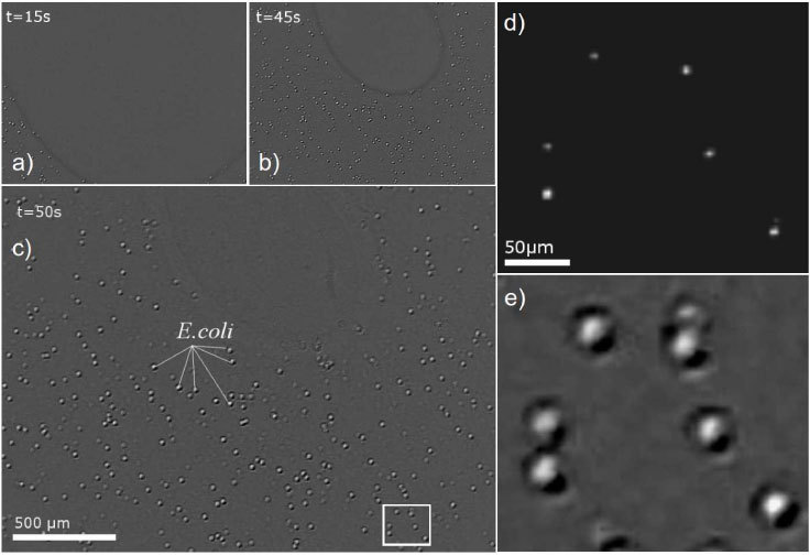
(a,b,c) Time lapse pictures acquired by lensless imaging during the evaporation of a 1µl droplet containing ~1000 E.coli DS-red (Cy3)/μl leading to the formation of a thin wetting film. The FOV of the CMOS sensor is 4.3 mm2 which corresponds approximately to 30% of a 1µl droplet evaporation surface. (d,e) FOV corresponding to the white rectangle in (c) imaged by means of (d) fluorescence microscopy (x5/0.15 NA) and (e) lensless imaging.
Figure 4 shows E.coli bacteria imaged by the lensless imaging device during the complete evaporation of a 1µl droplet containing E.coli bacteria. Prior evaporation, the pattern corresponding to the bacteria in the droplet is very faint and hardly detectable. The bacteria can be clearly detected while they are in the meniscus, at the interface of air, glass and liquid, but the signal vanishes after complete evaporation. Fixing the thin wetting film embedding the micro-object is thus one of the key steps making the new technique effective. This can be achieved using hydrophilic cover glass (water droplet contact angle of 4°) and a buffer with the proper surface tension and saline concentration. In all experiments, we are using a regular 10 mM Tris HCl pH8 buffer with 0.1% of TWEEN® 20 (Sigma-Aldrich P9416) and cover glass which are carefully cleaned with Ethanol and ultrasound. Under these conditions we are able to obtain thin wetting film of a few mm in diameter and a mere few μm thick that can remain for minutes to hours (Figs. 5 and 6). The thickness of few µm is deduced from the fact that 5μm beads systematically crack the film. In the presence of a controlled thin wetting film it is then possible to acquire images of 1-5 μm particles in very good conditions (Fig. 6). Even with a standard CMOS sensor, it is possible to image E.coli and Bacillus subtilis bacteria with a measured SNR of 45 ± 10 [33dB, Figs. 2(b), 6 and 7 ]. To our knowledge these are amongst the smallest particles imaged by means of lensless imaging with such a large SNR. In comparison S. Seo has reported image of E.Coli with a SNR of 15.11dB [8].
Fig. 5.

Long term micro-lens effect. (a) Timecourse of the intensity and (b) images of E.coli bacteria acquired with lensless imaging as a function of the evaporation time. The bacteria is first undetectable (1), but is revealed when in the meniscus (2) and is amplified after thin film formation (3). The glass cover slip is here hydrophilic, a thin wetting film remains after the evaporation and so does the image of E.coli bacteria.
Fig. 7.

Intensity profiles recorded in the presence of a thin wetting film of (a) 1μm diameter polymer beads, (b) 5μm diameter polymer beads and (c) Bacillus subtilis. The blue bold line corresponds to the mean value.
The pattern resulting from the micro-lens effect is not a holographic diffraction pattern as described in [7]. It will not allow bacteria species identification based on cell signature recognition [7] or hologram raw reconstruction [10]. But bacteria species identification by means of lensless imaging has not been fully demonstrated yet. Spectroscopic optical methods, like Raman spectroscopy, seem more relevant for identifying bacteria sub-species [3,4]. We consider that our technique may offer a cost-effective tool to detect and locate bacteria prior applying spectroscopic identification methods. Therefore in the following we will focus on detection efficiency and co-localization error measurements obtained with this novel lensless imaging technique.
2. Results
In order to assess the technique of thin wetting film lensless imaging, we have performed comparison against conventional fluorescence microscope images acquired with an Olympus Provis AX70 (magnification x5 and x20). Using fluorescent bacteria like E.coli DS-red (Cy3) was not satisfactory, as the lensless imaging counts more bacteria than the fluorescence microscope. This is due to the weak and heterogeneous fluorescence of the bacteria population. The following measurements are thus made with 1µm fluorescent polymer beads (Duke Scientific Corp. G0100) which are easily detected and located using fluorescence microscopy. Figure 8 shows the comparison of a single frame captured by the lensless imaging device [Fig. 8(a), 2.4x1.8 mm2 FOV] against a mosaic composed of 15 fluorescence microscopy images [Fig. 8(b), 1.81x1.33mm2 FOV]. Processing of lensless images acquisition was developed in Matlab® using an iterative pattern recognition algorithm based on a normalized cross-correlation scheme without ‘a priori’ information. A white disc (16x16 pixels, 45*45 µm2) is first used by the algorithm as the pattern to be detected. The detected patterns are averaged to form a new pattern and the image is reprocessed with this new pattern. The process is iterative until the difference between two consecutives averaged patterns is less than 1%. In this way the detection results do not depend on an imposed pattern. For the fluorescence microscopy images, gray-level thresholding and image segmentation are performed to detect the fluorescent beads. The comparison of these two modalities allows us to characterize the lensless imaging in terms of detection efficiency and percentage of false positives detections. As an example, Fig. 8(c) shows that detection efficiency reaches 81% for a total of ~700 1µm beads with 5% false positives. We have further performed analyses on a large data set of 21 comparisons totalizing 6300 beads. Results are shown in Fig. 9(a) .
Fig. 8.
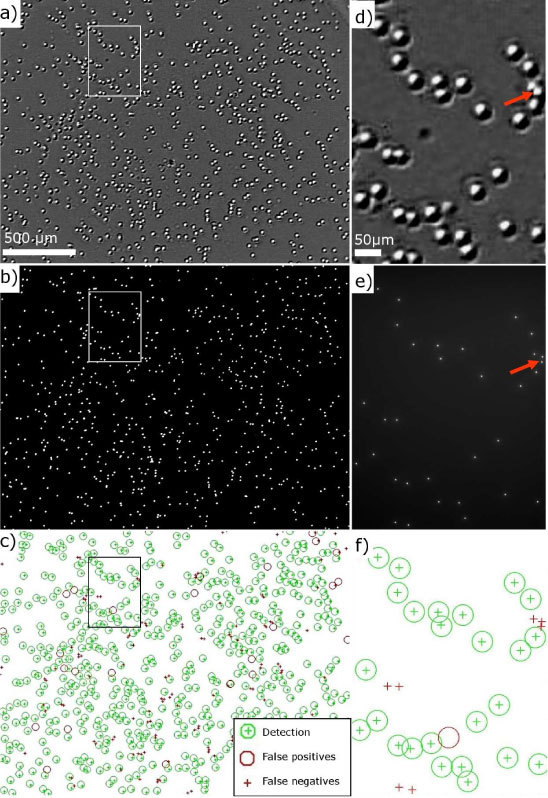
Image of ~700 1µm beads by means of (a) lensless imaging in thin wetting film and (b) fluorescence microscopy (x5/0.15 NA). (c) Detection performance of the lensless imaging obtained by comparison of (a) and (b). (d,e,f) Zoomed images of (a,b,c) respectively (white rectangle).
Fig. 9.
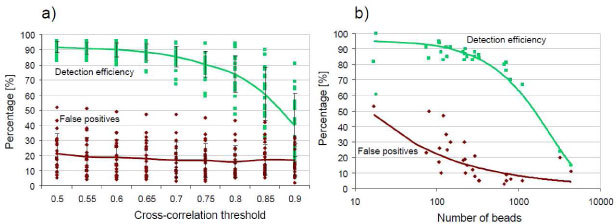
Detection efficiency and false positives percentage as a function of (a) the correlation threshold (200-300 1µm beads) and (b) the number of beads present in the FOV of the lensless imaging (images compiled with a cross-correlation threshold of 0.7). The bold lines correspond to mean values.
A good compromise between large detection efficiency and low false positives is found for a cross-correlation threshold of 0.7 applied in the detection algorithm. This results in a detection efficiency of 85 ± 7% with 17 ± 12% false positives. The false negative detections are found in the evaporation outer ring and when beads are too close one from another resulting in overlapping beads signature. The resolution limit to distinguish two adjacent micro-objects is about 30µm as shown in Figs. 8(d) and 8(e), which sets an upper limit to the number of beads that can be efficiently detected with this lensless imaging technique. Figure 9(b) shows that the detection efficiency decreases significantly when the number of beads exceeds 2000 (~500 beads/mm2). Furthermore, there is no way ensuring single micro-objects per micro-lens pattern. This is shown in Figs. 8(d) and 8(e) where closely packed beads can result in a single micro-lens pattern (red arrows).
The technique presents a lower limit, below 50 beads the thin wetting film becomes unstable and too thin to distinguish the beads from the saline surroundings. Maintaining the detection efficiency at 85% results then in a large number of false positives. Between 100 and 1000 beads however the evaporation is well controlled and the obtained image quality allows applying the dedicated detection algorithm.
In order to perform precise localization comparison, x20 magnification fluorescence microscopy serves as a reference (459x338μm2 FOV). Lensless imaging acquisition is thus cropped and upsampled by a factor of 9 using bicubic interpolation (Fig. 10 ) to fit with the fluorescence acquisition. Image registration is used to align the two images by means of a least square root method applied on the x, y positions of the detected beads. With fluorescence microscopy, the bead position is given by the centroid of the fluorescence spot. With lensless imaging, the position is given by the pixel corresponding to a local maximum of pattern cross-correlation. Figure 11 shows the co-localization error distribution over 640 detections of 1µm beads. The co-localization error is σ1D = 1.1 µm demonstrating that sub-pixel accuracy can be obtained.
Fig. 10.
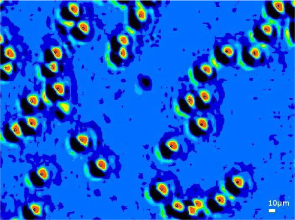
Lensless imaging of 1µm beads in a thin wetting film. The image is upsampled by a factor 9. Intensities are indicated in 16 colors on a linear scale. Overplotted in black are the centroid of the fluorescence detection (cross) and lensless imaging position (circle).
Fig. 11.

Co-localization error distribution measured on the lensless imaging device with the x20 magnification fluorescence microscopy serving as reference. The distribution compiles 640 detections of 1 µm beads over 21 different acquisitions.
3. Conclusion
We proposed a new scheme for lensless imaging of micro-objects. The new technique relies on the formation of liquid micro-lens on top of each object when evaporating µl droplets. Micro-objects as small as 1µm beads can be detected with 85% efficiency, a SNR of 45 and can be localised with a precision of σ1D = 1.1 µm. This technique will serve as a pre-positioning tool for the Raman spectroscopy identification of single bacteria.
References and links
- 1.Kirschner C., Maquelin K., Pina P., Ngo Thi N. A., Choo-Smith L. P., Sockalingum G. D., Sandt C., Ami D., Orsini F., Doglia S. M., Allouch P., Mainfait M., Puppels G. J., Naumann D., “Classification and identification of enterococci: a comparative phenotypic, genotypic, and vibrational spectroscopic study,” J. Clin. Microbiol. 39(5), 1763–1770 (2001). 10.1128/JCM.39.5.1763-1770.2001 [DOI] [PMC free article] [PubMed] [Google Scholar]
- 2.Goodacre R., Timmins E. M., Burton R., Kaderbhai N., Woodward A. M., Kell D. B., Rooney P. J., “Rapid identification of urinary tract infection bacteria using hyperspectral whole-organism fingerprinting and artificial neural networks,” Microbiology 144(5), 1157–1170 (1998). 10.1099/00221287-144-5-1157 [DOI] [PubMed] [Google Scholar]
- 3.Harz M., Kiehntopf M., Stöckel S., Rösch P., Straube E., Deufel T., Popp J., “Direct analysis of clinical relevant single bacterial cells from cerebrospinal fluid during bacterial meningitis by means of micro-Raman spectroscopy,” J Biophotonics 2(1-2), 70–80 (2009). 10.1002/jbio.200810068 [DOI] [PubMed] [Google Scholar]
- 4.Guicheteau J., Christesen S., Emge D., Tripathi A., “Bacterial mixture identification using Raman and surface-enhanced Raman chemical imaging,” J. Raman Spectrosc. (2010), to be published. 10.1002/jrs.2601 [DOI] [Google Scholar]
- 5.Mariella R., Jr, “Sample preparation: the weak link in microfluidics-based biodetection,” Biomed. Microdevices 10(6), 777–784 (2008). 10.1007/s10544-008-9190-7 [DOI] [PMC free article] [PubMed] [Google Scholar]
- 6.Su T. W., Seo S., Erlinger A., Ozcan A., “High-throughput lensfree imaging and characterization of a heterogeneous cell solution on a chip,” Biotechnol. Bioeng. 102(3), 856–868 (2009). 10.1002/bit.22116 [DOI] [PMC free article] [PubMed] [Google Scholar]
- 7.Seo S., Su T. W., Tseng D. K., Erlinger A., Ozcan A., “Lensfree holographic imaging for on-chip cytometry and diagnostics,” Lab Chip 9(6), 777–787 (2009). 10.1039/b813943a [DOI] [PMC free article] [PubMed] [Google Scholar]
- 8.Mudanyali O., Erlinger A., Seo S., Su T.-W., Tseng D., Ozcan A., “Lensless on-chip imaging of cells provides a new tool for high-throughput cell-biology and medical diagnostics,” J. Vis. Exp. 34, (2009). [DOI] [PMC free article] [PubMed] [Google Scholar]
- 9.Kim M.-S., Scharf T., Herzig H. P., “Small-size microlens characterization by multiwavelength high-resolution interference microscopy,” Opt. Express 18(14 Issue 14), 14319–14329 (2010). 10.1364/OE.18.014319 [DOI] [PubMed] [Google Scholar]
- 10.Oh C., Isikman S. O., Khademhosseinieh B., Ozcan A., “On-chip differential interference contrast microscopy using lensless digital holography,” Opt. Express 18(5 Issue 5), 4717–4726 (2010). 10.1364/OE.18.004717 [DOI] [PMC free article] [PubMed] [Google Scholar]


