Abstract
We present an experimental approach that allows exposure of cells plated on a single coverslip to multiple distinct environments. The original chamber design created a small region of injury using geometrically defined flows of the control and ischemic solutions. Modifications of the original chamber design presented in this article produce a range of flow patterns that can be advantageous for a variety of imaging applications. These applications include: experiments that address effects of different treatments applied to a cell network, parallel testing of negative and positive controls using a single coverslip, border effect studies, evaluation of the treatment’s reversibility, and simultaneous monitoring of a cell layer loaded with different fluorescent indicators. The method also can be used to reveal both micro- and macroscopic features of propagation, conduction, and cell coupling in a normal or altered cardiac cell network. These possibilities are illustrated in cultures of neonatal rat cardiomyocytes using oxidant- and calcium-sensitive fluorescent indicators.
Keywords: Cultured cardiomyocytes, fluorescent indicators, calcium transients, oxidative stress, imaging
Introduction
Recent advancements in imaging technology and the development of a wide range of fluorescent indicators for in vivo monitoring of intracellular processes have enabled researchers to rapidly gain new ground in understanding cardiovascular physiology and disease. An exciting development in this field is the ability to monitor effects within multicellular preparations with resolution sufficient to observe cellular events while being able to visualize the entire network. Our attempts to visualize such processes led to the development of a local injury approach that employs a specially designed perfusion chamber (1). The method proved to be an excellent tool to induce and study ischemia-reperfusion arrhythmias (2). This article discusses other possibilities offered by the local injury approach and presents further modifications of the original perfusion chamber. We believe that this new technique is of interest to a wide variety of investigators, in particular to cardiovascular pharmacologists and toxicologists.
Materials and Methods
Chemicals
Collagenase II was obtained from Worthington (Freehold, NJ). Media and porcine trypsin were obtained from Gibco BRL (Grand Island, NY). Fluorescent indicators were purchased from Molecular Probes Inc. (Eugene, OR). Fetal bovine serum, xanthine oxidase, bovine liver catalase, and all other chemicals were purchased from Sigma Chemical Co (St. Louis, MO).
Myocyte Isolation
Cardiomyocytes from 1- to 2-d-old Sprague-Dawley rats were obtained by an enzymatic digestion procedure (1). All experiments involving animals were performed according to the Institutional Committee on Animal Care and Use of the Texas Tech University Health Sciences Center, which follows federal and state guidelines. Hearts were removed, rinsed in a cold calcium- and magnesium-free Hank’s buffered salt solution, and minced into ~1 mm3 pieces. Tissue chunks were incubated overnight at 2°C in calcium- and magnesium-free Hank’s buffered salt solution containing 0.1 mg/mL trypsin. The next day, they were washed with calcium- and magnesium-free Hank’s buffered salt solution and treated with 0.4 mg/mL soybean trypsin inhibitor. The tissue was then collected into Leibovitz’s medium containing 0.8 mg/mL collagenase II and shaken for 20 min at 37°C. The cells were then gently triturated, passed through a cell strainer to remove any undigested pieces, and centrifuged for 3 min at 17.5 g. The pellet was resuspended in Dulbecco’s modified Eagle’s medium supplemented with 10% fetal bovine serum.
Cell Plating and Culture
The cells were preplated for 1 h to extract fibroblasts and endothelial cells, which attach more rapidly than myocytes. Unattached cells were then collected, counted and plated in a culture dish containing 25-mm laminin-coated glass coverslips (105 cells/cm2). Cells were then kept under standard culture conditions in Dulbecco’s modified Eagle’s medium, supplemented with 5% fetal bovine serum, 10 U/mL penicillin, 10 μg/mL gentamicin, and 1 μg/mL streptomycin. On the third day after plating, the cells formed interconnected, confluent networks that exhibited rhythmic, spontaneous contractions and were used for an additional 3–4 d.
Fluorescent Indicators
Dichlorofluorescein (DCF) was used as an oxidant sensitive dye (3) and Fluo-4 was employed to record calcium transients (1). Cells were loaded with a cell-permeable form of fluorescent indicator (10 μM of DCFH-diacetate for 15 min or 5 μM Fluo-4AM for 1 h) at room temperature, followed by a 10-min incubation with the control Tyrode. To delineate flow patterns 1 μM fluorescein and rhodamine were included into the perfusate.
Experimental Chamber
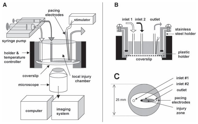
The stainless steel holder was used to mount a glass coverslip on the raised surface of a plastic chamber, which contains several inlets and a single outlet (Fig. 1). The polished-side surface of the chamber provided an airtight contact with the coverslip, whereas the Plexiglas ceiling left a 300-μM open perfusion space. Superfusion solutions were driven by a multi-syringe pump (Harvard Apparatus) loaded with 5-, 10- and 30-mL glass syringes. The syringe diameter determines the flow rates within the chamber and sizes of the zones. The stainless steel holder was mounted in a microincubator (Medical Systems Corporation) equipped with a Peltier controller, which maintains a constant temperature inside the chamber.
Fig. 1.
Overall design. (A) Setup includes: local injury chamber, Peltier temperature controller, microscope, imaging system, computer, automatic syringe pump, and stimulator. (B) Cross-section of the chamber. (C) Bottom view: only the plastic holder and coverslip are shown. Injury zone is depicted in gray.
Monolayer Pacing
Experiments can be conducted in both quiescent and spontaneously beating cultures, or external pacing can be employed. In our studies pacing was accomplished with two platinum electrodes embedded into the top part of the Plexiglas chamber. They stimulated a small myocyte cluster immediately beneath them, and a wave of action potentials then spread through the rest of the network. The monophasic 1.2-ms pulses were applied starting at a pacing voltage of 0.4 V/cm (the distance between electrodes was 1 mm) and then increased in 0.1-V increments until each pacing impulse was captured by the cell network. The monolayer was then continuously paced by a voltage 20% higher than the excitation threshold.
Experimental Protocols
Myocytes were superfused with a control Tyrode solution (136 mM NaCl, 0.8 mM MgCl2, 4.0 mM KCl, 1.2 mM CaCl2, 5.6 mM glucose, and 10 mM HEPES, pH 7.3) through inlet #1 and the basal pattern and fluorescence intensity profiles within each zone were recorded. After 5–10 min, inlets #2–5 were opened, and the solutions of interests started to flow over the coverslip, creating zones depicted in Fig. 2. The ischemic environment in this study refers to a solution that reproduced certain elements of the extracellular milieu of ischemic cells (4). It consisted of: 136 mM NaCl, 0.8 mM MgCl, 8 mM KCl, 1.2 mM CaCl2, 20 mM deoxyglucose, 5 mM HEPES, and 5 mM MES, 6.5 pH. Reperfusion (i.e., washout) was achieved by turning off the flow from inlets 2–5. It resulted in a rapid restoration of the control Tyrode flow.
Fig. 2.
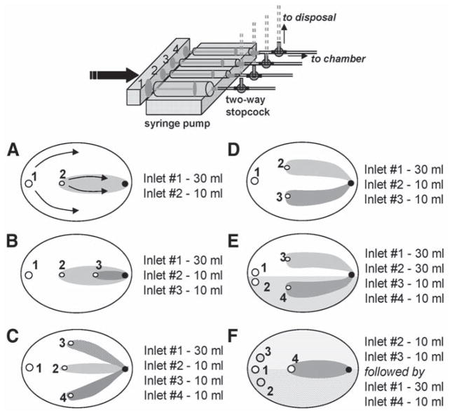
Modifications of the local injury chamber. A variety of flow patterns can be obtained by changing inlet positions and syringes size. Inlets are shown as open circles and marked by the numbers. Corresponding syringe sizes for the depicted patterns are shown on the right. The outlet opening is shown as a black circle. (A) Single injury zone chamber. Arrows show the direction of the flow within the two zones. The injury zone (I-zone) is shown in gray and the control zone (C-zone) is shown in white. (B) Nested injury chamber that creates three distinct environments, including two injury zones. (C) Trefoil chamber that creates one C-zone and three small I- zones. (D) Double injury chamber. (E) Double injury chamber with split C-zone. This design allows side-by-side comparison of two reperfusion protocols. (F) Double staining chamber. It allows staining of a cell coverslip with two different dyes (shaded areas). The extracellular dyes are then washed out with the control solution (inlet 1), which is followed by an application of the injury solution via inlet 4. The I-zone (shown in gray) is then created over the two areas of cell network stained with different fluorescent indicators.
Acquisition System
Monolayers were imaged with either low-power magnification objectives to capture several zones simultaneously or higher magnification objectives to monitor intracellular changes. The acquisition system consisted of an Olympus XL-70 inverted microscope and a BioRad MRC 1024 confocal imaging system. The 488-nm line of the argon laser was used for DCFH and Fluo-4 excitation. The dual excitation with 488/568 nm lines of the argon/krypton laser was used for fluorescein/rhodamine experiments shown in Fig. 3.
Fig. 3.
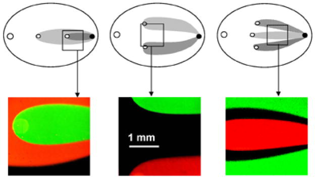
Experimental flow patterns. Images were acquired using 10 μM rhodamine and fluorescein to delineate flow geometry. Boxes correspond to the field of view when ↔ 4 objective is used.
Results and Discussion
Local Injury Chamber
The original chamber design created a single, small oval area perfused with the solution of interest within a larger area superfused with the control solution (Fig. 1). We named the small zone the I-zone (injury zone, or zone of interest), whereas the rest of the control network was called the C-zone (control zone). The overall experimental setup and chamber design is presented in Fig. 1. The detailed description of the chamber including flow profiles and times required for establishing the flow can be found in our previous study (1). The stable (in both time and space) geometry of the flow was achieved by implementing two simple but essential technical features. The first feature is a single outlet coupled with the closed design of the chamber. This way the inflow solutions are being “pushed” out via a single outlet and no pump or suction is required. The second aspect is the use of a multisyringe pump that employs a single moving shaft for all the syringes. The ratio of the inflow rates is thus determined by the diameter (volume) of the syringes, which feed into each inlet. The ratio of the inflow rates remains the same even if the speed of the pump itself is altered. This feature allows one to diminish small variations in the pump rate that otherwise will shift the flow pattern. We have shown that the border gradient between the C-zone and the I-zone remains stable with <100-micron accuracy for 2–3 h of constant perfusion (1).
Previous attempts to visualize the border area between two experimental environments included alternative designs of dual-perfusion chambers (5,6). However, these chambers did not employ the previously described technical features, and the temporal stability of the established flow gradients was not discussed. Unfortunately, the lack of follow-up studies using these chambers precludes a comparison of their usefulness with the local injury chamber shown in Fig. 1.
The first advantage of the local injury approach is that it allows simultaneously quantifying parameters of the injured (i.e., treated) and the control cells. The second advantage is that it allows the study of how a small treated area affects the behavior of the rest of the excitable cell network. For example, when the I-zone cells are perfused with ischemia-like solution, the C-zone beating pattern remains unaffected (2). However, washout of ischemia-like solution causes prominent arrhythmias that spread into the control networks and disrupt the regular pacing pattern (2). The third advantage is the ability to rapidly switch from low- to high-magnification objectives during the experiment, which allows the visualization of the intracellular events that underlie the network behavior. Finally, besides remarkable spatiotemporal stability of the I-zone, the suggested chamber design allows rapid reperfusion of the injured area or reestablishment of the same flow pattern using a different solution (by turning off and on the three-way valves connected to the corresponding inlets, see Fig. 2). This feature makes the local injury approach a valuable tool to study reperfusion events.
Multiple Injury Chambers
Modifications of the original chamber design allows one to create a variety of the flow patterns over the coverslip (Fig. 2). The images of the corresponding flow patterns as they are seen using ×4 magnification objective are shown in Fig. 3. The presented chamber modifications can be useful in several applications, including the following.
Imaging Experiments that Address Effects of Different Concentrations/Conditions
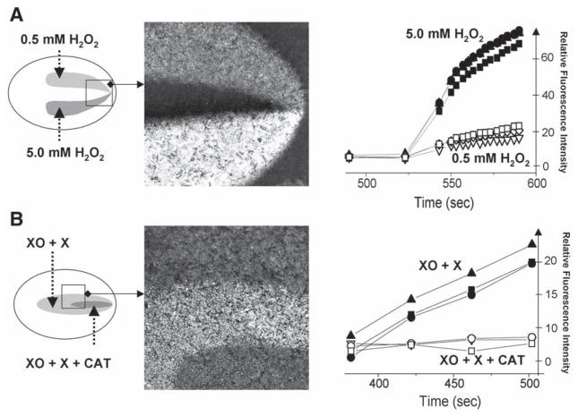
One of the major limitations of quantifying the response of live preparations in imaging experiments is the inherent variability between individual cover-slips. It includes intrinsic variability and variability because of handling. The latter includes differences in dye loading/washout conditions, time cells spend outside the incubator, age of the culture, incidental light exposure in case of light-sensitive indicators, and other factors. Ability to simultaneously test multiple conditions using the same coverslip eliminates these factors and thus significantly improves data acquisition. It also allows for collecting parallel data within the same period. An example of such an experiment using dual injury chamber is presented in Fig. 4A. It shows the response of the DCFH-loaded cardiomyocytes to different hydrogen peroxide concentrations. Traces correspond to several regions of interests positioned within two zones. The graph shows the initial, linear phase of the response. The image (taken 3 min after peroxide addition) illustrates large difference in DCF levels between the two peroxide concentrations, as well as between the treated areas and the control network. Notably, high hydrogen peroxide concentrations were used for this particular experiment to facilitate visualization of the differences between the two concentrations and the control area.
Fig. 4.
Multiple injury experiments conducted in DCFH-loaded cardiac myocyte cultures. (A) This experiment was conducted using a double injury chamber. The two injury zones were perfused with the Tyrode solution containing 0.5 mM and 5 mM H2O2. Traces on the graph show rapid increase in fluorescence levels associated with the transition from DCFH to DCF. The traces were acquired from three different regions of interest positioned within each zone. The image illustrates large differences in fluorescence levels between the two areas and the control network. (B) This experiment was conducted using a nested injury chamber. The large injury zone was perfused with 0.2 U/mL xanthine oxidase and 1 mM xanthine, whereas the solution flowing via the small injury zone also included an additional 400 U/mL of catalase. The difference between the two areas illustrates the inability of superoxide anions to oxidize intracellular DCFH.
Parallel Testing of Positive and Negative Controls
One can significantly improve the statistical quality of the experiments if multiple injury approach is used for side-by-side comparisons between the treatment and its positive and negative controls. For example, additional outlets can be used for solutions containing substrate only, enzyme only or inhibitor only. Figure 4B illustrates this approach in DCFH-loaded cardiomyocytes using xanthine oxidase/xanthine reaction as a source of reactive oxygen species (7). The syringe connected to inlet 1 contains the control Tyrode; the syringe connected to inlet #2, xanthine oxidase (0.2 U/mL) and xanthine (1 mM); and the syringe connected to inlet #3, xanthine oxidase (0.2 U/mL), xanthine (1 mM), and catalase (400 U/mL). The xanthine oxidase uses xanthine as a substrate to continuously produce hydrogen peroxide and superoxide radicals (7). Presence of catalase in the media eliminates hydrogen peroxide while superoxide is still present. The data shown in Fig. 4B illustrate that hydrogen peroxide, not the superoxide anion, is capable of penetrating myocyte membranes and converting DCFH to the fluorescent DCF (3).
Repetitive Injury
The chamber design allows one to repetitively create and wash off the I-zone(s) on the exact same area of the coverslip. This is achieved by simply turning off and on the three-way valve, which is connected to the I-zone(s) inlet. Therefore, the same treatment can be applied several times to check reversibility of the effect. Alternatively, it can assist in studies that address exacerbation of the injury by its repetition. For example, in our previous study, we found a correlation between the number of ischemia-reperfusion episodes and the occurrence of the reperfusion arrhythmias (2). On the other hand, the protocol that employs repetitive treatment can be used to study cell preconditioning or related phenomena.
Microreperfusion Protocol
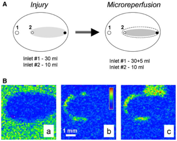
An increasing number of studies point to the boundary between injured and controlled regions as a potential source of abnormal activity, especially during reperfusion (2,8,9). Thus we have modified the original protocol that allows the reperfusion of the border cells only, whereas the rest of the network remain under either I-solution or C-solution flow (Fig. 5A). This was achieved by increasing the inflow rate of the C-solution (additional 5-mL syringe is added to inlet 1), whereas the inflow rate via inlet #2 remains the same. We named this protocol microreperfusion and hypothesize that it mimics physiological phenomena (2). Indeed, during local ischemia, border cells are likely to be “reperfused” as a result of vasodilatation of the neighboring blood vessels upon accumulation of metabolites. Figure 5B illustrates the experiment conducted using microreperfusion protocol. Specifically, it shows that the border zone serves as the origin of the tachyarrhythmic activity associated with reperfusion (more details can be found in [2]).
Fig. 5.
Microreperfusion protocol. Addition of the flow from an extra 10-mL syringe narrows the original I-zone (dotted area) because of the altered ratio of the inflow solutions. This results in a new flow distribution and a smaller I-zone (shown in gray). Therefore, only the border area of the original I-zone is reperfused with the control solution. Images acquired during the microreperfusion protocol conducted in Fluo-4 loaded cardiomyocyte network. Appearance of the injured area (A), localized propagation within border zone area (B), and spread (C) of the calcium transient wave can be clearly observed. Pseudocolor refers to intracellular calcium concentration. More details in the text and in the ref. 1.
Border and Its Width
The local injury approach offers a unique opportunity to study border zone effects. In addition, the width of the physical gradient that exists on the border between the two environments can be altered. If a fluorescent dye is included in the I-zone solution, the dye’s intensity profile reveals a sigmoidal change in I-solution concentration across the border area (1). Distance between the locations at which the I-solution concentrations is 10% and 90% of its maximum can be used to define physical border width. For the chamber that is 300 μm, the deep average physical border width is 180 μm (1). It can be changed by varying the distance between the glass coverslip and the plastic top of the chamber because this distance determines the degree of mixing between the inflow solutions.
Notably, one has to appreciate the possible difference between the physical border and the area where transition of physiological response occurs (i.e., functional border). The effects of the most active compounds on cells are highly nonlinear. Therefore, a 50% decrease in the compounds concentration will not result in a 50% decrease of its functional effect. Thus, at a given physical border width, both the content of the I-zone solution and the measured parameter determine the steepness of the functional border. For example, we have shown that the inclusion of a gap-junctional uncoupler in the I-zone narrowed its functional border by fourfold (1). The maximum intensity of [Ca2+]in transients across the border was used to reveal the width of the functional border zone in these experiments. The values of maximum Fluo-4 intensity associated with high systolic Cain levels were fitted into a sigmoidal curve, and border width was determined as the distance between 10% and 90% of the curve maximum intensity. The functional border zone was 120 ± 8 μM in the presence of 1 mM heptanol in I-solution as compared with 473 ± 51 μM without the uncoupler. Notably, the physical border width for the chamber used in these experiments was 180 μM (1).
Experiments with Cell Adhesion
One of the particularly interesting applications of the local injury approach is the study of cell adhesion. For example, if ischemia-like injury is followed by reperfusion with a neutrophil-containing solution, the neutrophils only attach to the cardiomyocyte or endothelial cell layer within the former I-zone (unpublished observations). Because neutrophil activation status can be easily affected by their handling, it maybe particularly useful to employ the local injury chamber for such experiments. Indeed, it allows comparison of the degree of attachment to the untreated and ischemic cells within the same coverslip. It also enables one to use positive controls (e.g., inclusion of phorbol ethers or interleukins) to ensure that neutrophils are functionally active.
Parallel Staining with Different Fluorescent Indicators
Significant insights can be gained from simultaneously monitoring two or more physiological parameters, such as from parallel measurements of action potential and calcium transients, oxidative stress and pH changes, or intracellular calcium and oxidative stress. In most cases, the same preparation can be stained with two (or more) fluorescent dyes and separate their optical signals based on the difference in either emission or excitation spectra. In some cases, however, dyes with very similar spectral properties (e.g., Fluo-4 and DCFH-DA) may be used. The local injury approach can then be used, specifically the camera design depicted in Fig. 2F. In these experiments, loading with fluorescent indicators is performed within the chamber itself using inlets 2 and 3 to perfuse the cells layer with dye 1 and 2, respectively. The flow from inlets 2 and 3 is then turned off and inlet 1 (control solution) is activated. After 5–10 min of equilibration/washout, inlet 4 (treatment solution) is turned on. This creates a flow pattern in which half of the I-zone is located in the Fluo-4-stained cell region and the other half is in the DCFH-DA stained cell region. The images and the signals acquired from the regions of interest positioned within each zone will then reflect either calcium or oxidant-sensitive changes and can be recorded using a single optical channel.
Method’s Applicability
The local injury approach is not limited to cultured cells or cardiac myocytes. It can be used for cells of any type that can be attached to glass or plastic coverslips. It can also be used for small fibers of either artificial or physiological origin.
The method can be used with a variety of fluorescent indicators in both single and dual emission/excitation modes. In our laboratory we have tested it in conjunction with voltage, calcium, and pH indicators, as well as oxidant-sensitive probes.
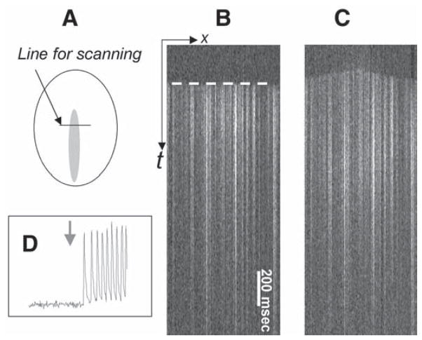
The approach can be used to address dynamic events that occur on a millisecond scale or to study slow effects that require 1–2 h treatments. If the confocal setup is used, the temporal resolution can be substantially increased by using the line scan mode of acquisition. In this mode the laser scans across the areas of interest with a temporal resolution of 2 ms/line and the events are observed in x-t mode (10). As an example, line scan images in Fig. 6 illustrate a shift of the pacemaker activity from the C-zone into the I-zone upon I-zone perfusion with 0.2 mM BaCl2. It occurs as a result of a barium-induced blockade of the inward rectifier potassium current, IK1 (11).
The imaging acquisition equipment is not limited to the confocal setup, but can be either a charge-coupled device or photo diode-based imaging system. However, when experiments are conducted with low magnification objectives (>×10), the depth of plane from which light is being acquired is increased. Therefore, the background fluorescence and the fluorescence from the chamber’s plastic top tend to obscure the signal from the cell layer. Real-time background subtraction allows alleviation of this drawback.
Fig. 6.
Local injury approach as a means to assess dynamic interactions between treated area and the surrounding control network. The experiment was conducted in Fluo-4-loaded myocyte cultures using x-t mode of acquisition. In this mode the fluorescence intensity values are collected along the fixed x-line every 2 ms and the line values are plotted sequentially, forming an x-t image. The front of the calcium transient wave (white dotted line) allows one to determine the direction of the propagating wave. (A) The diagram shows the position of the scanning line across the I-zone. (B) In the control conditions the front of the calcium transient wave is essentially flat (marked by a dotted white line) because paced calcium wave reaches the position of the scan line simultaneously. (C) Presence of 0.1 mM BaCl2 in the I-zone leads to shift of the pacemaker activity to the I-zone. In the line scan mode it can be seen as a change to a dome-shaped front of the calcium transients’ wave with the center in the I-zone. (D) The trace was acquired from the control area, where cells are continuously perfused with the control solution. However, on perfusion of the I-zone with BaCl2 (denoted with a gray arrow), the I-zone cells elicit tachycardia-like response in the entire monolayer, including the control area.
Limitations of the Method
The approach is not suitable to study paracrine effects. Because the I-zone cells and C-zone cells are being perfused constantly, compounds that are released into the extracellular space will be washed off via the outlet without reaching cells from the different zone.
Closed-chamber design prevents direct access to the cells; therefore, intracellular electrode recordings are not feasible.
Choosing the solutions has to be done before the experiment. Stopping the pump or reloading the syringes during the experiments will shift the shape and the position of the zones.
Words of Caution
The method itself and involved equipment is straightforward and affordable. However, it requires careful handling of all involved components. Simple but essential key points include the following.
Air bubbles in tubing, valves, and chamber itself have to be avoided. The dead spaces have to be prefilled by turning the syringe pump on before mounting the coverslip. The chamber is then turned upside down, and the coverslip with loaded cells is placed on the top of a large drop of the control solution. The coverslip is then pressed toward the plastic chamber and tightened by the screws in the stain-steel mount.
The syringe pump has to be well-adjusted because jerky shaft movement will result in flow shifts.
The end of the outlet tubing has to be positioned above the chamber level to avoid negative hydrostatic pressure.
Lipophilic dyes or chemicals tend to stick to the plastic chamber and tubing. For such experiments, an overnight wash of the chamber and its components in alcohol is advised to avoid future contaminations.
Acknowledgments
This work was supported by the National American Heart Association and by the National Institutes of Health (HL62419).
References
- 1.Arutunyan A, Webster DR, Swift LM, Sarvazyan N. Localized injury in cardiomyocyte network: a new experimental model of ischemia-reperfusion arrhythmias. Am J Physiol Heart Circ Physiol. 2001;280:H1905–H1915. doi: 10.1152/ajpheart.2001.280.4.H1905. [DOI] [PMC free article] [PubMed] [Google Scholar]
- 2.Arutunyan A, Swift LM, Sarvazyan N. Initiation and propagation of ectopic waves: insights from an in vitro model of ischemia-reperfusion injury. Am J Physiol Heart Circ Physiol. 2002;283:H741–H749. doi: 10.1152/ajpheart.00096.2002. [DOI] [PMC free article] [PubMed] [Google Scholar]
- 3.Swift LM, Sarvazyan N. Localization of dichlorofluorescein in cardiac myocytes: implications for assessment of oxidative stress. Am J Physiol Heart Circ Physiol. 2000;278:H982–H990. doi: 10.1152/ajpheart.2000.278.3.H982. [DOI] [PMC free article] [PubMed] [Google Scholar]
- 4.Vanden Hoek TL, Shao Z, Li C, Zak R, Schumacker PT, Becker LB. Reperfusion injury on cardiac myocytes after simulated ischemia. Am J Physiol. 1996;270:H1334–H1341. doi: 10.1152/ajpheart.1996.270.4.H1334. [DOI] [PubMed] [Google Scholar]
- 5.Hyatt CJ, Lemasters JJ, Muller-Borer BJ, Johnson TA, Cascio WE. A superfusion system to study border zones in confluent cultures of neonatal rat heart cells. Am J Physiol. 1998;274:H2001–H2008. doi: 10.1152/ajpheart.1998.274.6.H2001. [DOI] [PubMed] [Google Scholar]
- 6.Atsma DE, Bastiaanse EM, Ince C, van der Laarse A. A novel two-compartment culture dish allows microscopic evaluation of two different treatments in one cell culture simultaneously. Influence of external pH on Na+/Ca2+ exchanger activity in cultured rat cardiomyocytes. Pflugers Arch. 1994;428:296–299. doi: 10.1007/BF00724510. [DOI] [PubMed] [Google Scholar]
- 7.Sarvazyan N, Askari A, Klevay LM, Huang WH. Role of intracellular SOD in oxidant-induced injury to normal and copper-deficient cardiac myocytes. Am J Physiol. 1995;268:H1115–H1121. doi: 10.1152/ajpheart.1995.268.3.H1115. [DOI] [PubMed] [Google Scholar]
- 8.Maldonado C, Li ZY, Wead WB, Szabo T, Kupersmith J. Mechanisms of triggered activity induction at the border zone of normal and abnormal cardiac tissue. J Electrocardiol. 1996;29:309–318. doi: 10.1016/s0022-0736(96)80095-1. [DOI] [PubMed] [Google Scholar]
- 9.Pogwizd SM, McKenzie JP, Cain ME. Mechanisms underlying spontaneous and induced ventricular arrhythmias in patients with idiopathic dilated cardiomyopathy. Circulation. 1998;98:2404–2414. doi: 10.1161/01.cir.98.22.2404. [DOI] [PubMed] [Google Scholar]
- 10.Arutunyan A, Pumir A, Krinsky VI, Swift LM, Sarvazyan N. Behavior of ectopic surface: effects of beta-adrenergic stimulation and uncoupling. Am J Physiol Heart Circ Physiol. 2003;285:H2531–H2542. doi: 10.1152/ajpheart.00381.2003. [DOI] [PMC free article] [PubMed] [Google Scholar]
- 11.Delmar M, Jalife J. Low Ba-induced pacemaker current in well-polarized cat papillary muscle. Am J Physiol Heart Circ Physiol. 1987;252:H258–H268. doi: 10.1152/ajpheart.1987.252.2.H258. [DOI] [PubMed] [Google Scholar]


