Abstract
A novel approach toward construction of robots is based on a concentric combination of precurved elastic tubes. By rotation and extension of the tubes with respect to each other, their curvatures interact elastically to position and orient the robot’s tip, as well as to control the robot’s shape along its length. In this approach, the flexible tubes comprise both the links and the joints of the robot. Since the actuators attach to the tubes at their proximal ends, the robot itself forms a slender curve that is well suited for minimally invasive medical procedures. This paper demonstrates the potential of this technology. Design principles are presented and a general kinematic model incorporating tube bending and torsion is derived. Experimental demonstration of real-time position control using this model is also described.
Keywords: Continuum robots, flexible arms, kinematics, medical robots and systems, telerobotics
I. INTRODUCTION
MINIMALLY invasive medical procedures involve the manipulation of tools, sensors, and prosthetic devices inside the body that lead to minimum damage of surrounding tissue structures. In many cases, navigation to the surgical site requires the instrument to be steered along 3-D curves through tissue to avoid bony or sensitive structures (percutaneous procedures) or following the interior contours of a body orifice (e.g., the nasal passages) or body cavity (e.g., the heart). Once at the surgical site, it is often necessary to control the position and orientation of the instrument’s distal tip while the proximal inserted length is held relatively immobile.
The instruments used in minimally invasive procedures can be grouped into three general categories. The first category includes straight flexible needles that are used for percutaneous procedures in solid tissue. The needle is steered along a curved insertion path by the application of lateral forces at the needle base or tip as the needle is advanced into the tissue. Since the needle is initially straight, both base- and tip-steering methods rely on tissue reaction forces to flex the needle along a curved insertion path. Consequently, these instruments possess no ability to produce lateral tip motion without further penetration into solid tissue.
The second category of instruments is composed of a straight, stiff shaft with an articulated tip-mounted tool (e.g., forceps). Both hand-held and robotic instruments (e.g., da Vinci, Intuitive Surgical, Inc.) [1] of this type are in common use for minimally invasive access of body cavities (e.g., chest or abdomen). The shaft must follow a straight-line path from the entry point of the body to the surgical site. Lateral motion of the tip depends on pivoting the straight shaft about a fulcrum typically located at the insertion point into the body. This pivoting motion produces tissue deformation proportional to the thickness of tissue from the entry point to the body cavity.
The third category of instruments includes elongated, steerable devices, such as multistage microrobot devices, which are typically used for entry through a body orifice, and steerable catheters, which are most often used for percutaneous access of the circulatory system. Multistage microrobot devices are typically mounted at the distal end of a rigid shaft and include a flexible backbone that has a series of regularly spaced platforms. Control elements, e.g., wires or tubes, attach to the distal platform and slide through all proximal platforms. For example, in [2], the control elements are tubes that act as secondary backbones and enable shape control through push–pull actuation. These devices are typically sufficiently rigid to support their own weight as well as to apply appreciable lateral forces to the surrounding tissue. An alternate novel technology enables extension along an arbitrary 3-D curve [3]. This technology is, however, nonholonomic in that lateral motion of the tip is only accomplished in combination with tangential motion.
In contrast, steerable catheters include an elongate member of sufficient flexibility to conform to the curvature of the vessel through which it is advanced. Steering is achieved by the use of one or more wires attached to the distal end of the elongate member disposed along the catheter’s length [4]. User actuation (e.g., pulling) of the wires causes the distal portion of the elongate member to flex in one or more directions. Alternately, an external magnetic field can be used to position the catheter tip (Stereotaxis, Inc.) [5].
Concentric tube robots possess the best properties of all three types of instruments. With cross sections comparable with needles and catheters, they are nevertheless capable of substantial actively controlled lateral motion and force application along their length. Since robot shape can be controlled, they enable navigation through the body along 3-D curves. Furthermore, the lumen of the tubes can house additional tubes and wires for control of articulated tip-mounted tools. An example is shown in Fig. 1.
Fig. 1.
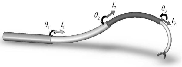
Concentric-tube robot comprising four telescoping sections that can be rotated and translated with respect to each other.
Thus, the technology holds the potential to enable many new minimally invasive interventions. An important class of applications for such a device would be to enter a body lumen by steering through tissue or through a body orifice. Once inside the lumen, the proximal portion can remain relatively fixed while the distal portion manipulates tools within the lumen to perform minimally invasive surgery.
The kinematic modeling for real-time control of these robots is a challenge in comparison to that of traditional robots whose links are relatively rigid and whose joints are discrete. The forward kinematics can be cast as a 3-D beam-bending problem in which the kinematic input variables (tube rotations and displacements at the proximal end) enter the problem as a subset of the boundary conditions. The remaining boundary conditions comprise point forces and torques applied to the distal ends of the tubes. Contact along the robot’s length (e.g., with tissue) generates additional distributed and point loads.
Thus, it can be anticipated that the most general kinematic model can be expressed as a two-point boundary-value problem that involves a differential equation with respect to arc length along the common centerline of the tubes. Phenomena that may be included in the model are bending, torsion, friction, shear, axial elongation, and nonlinear constitutive behavior.
Since real-time control necessitates the balance of the accuracy of the model with efficiency of its computation, efforts to date have modeled curved portions of the tubes as torsionally rigid [10]-[15]. The torsionally rigid model, which was first derived in [10], results in an algebraic expression for curvature of the combined tubes that can be analytically integrated to yield position and orientation of the robot’s tip. Models of this type have been demonstrated to provide reasonable performance in combination with real-time sensing of the tip frame (teleoperation in [13] and image servoing in [15]).
Including torsional twist in the straight-transmission lengths of the tubes has also been proposed in [11] and implemented by the use of online root finding in [15]. Instabilities that arise from the interaction of transmission-length torsion and curved-length bending have been investigated using an energy approach in [14].
While it was shown in [12] that closed-form inverse kinematic solutions can be derived for simple concentric-tube robots, they are difficult to obtain in general. Jacobian-based inverse kinematics that use the algebraic curvature model were first formulated in [12] and experimentally implemented in [13]. Inclusion of torsional twist in straight transmission lengths is reported in [15].
The contribution of this paper is to provide a framework for the design and kinematic modeling of concentric-tube robots that enables accurate real-time position control. The paper is arranged as follows. Section II presents design guidelines for the production of clinically relevant robots and describes the origins of concentric-tube technology. Section III derives a new kinematic model that is more accurate than prior models since it includes torsion along the entire lengths of the tubes and is also able to predict torsion-bending instabilities for curved tubes [16]. Implementation of closed-loop position control based on the kinematic model is described in Section IV and its experimental evaluation appears in Section V. Conclusions are given in Section VI.
II. Design of Concentric-Tube Robots
A. Overview
When curved tubes are inserted inside each other, their common axis conforms to a mutually resultant curvature. By relative translations and rotations of the tubes, both the curvature as well as the overall length of the robot can be varied. The first robots of this type composed of two tubes were presented in [7]-[9]. Robots composed from three or more tubes were first proposed in [10] and [11].
To understand the capabilities of the technology, it is useful to consider the interaction of two concentrically combined tubes. Limiting cases of their interaction correspond to when the ratio of bending stiffnesses for the two tubes is 1) very large, such that the shape of one tube dominates that of the other, and 2) the ratio is approximately one, such that the tubes’ shapes interact equally to determine the overall shape. Each of these cases is described next.
1) Domination-Stiffness Tube Pair
Since the bending stiffness of one tube is much larger than that of the other, the pair of concentric tubes conforms to the curvature of the stiffer tube. When the more flexible tube is translated such that it extends beyond the end of the stiff tube, the extended portion relaxes to its original curvature.
This is illustrated in Fig. 2 for the case of a stiff, straight outer tube and a curved, inner flexible tube. As shown in Fig. 2(b), once the flexible tube is extended, the pair has two independent degrees of freedom (DOFs) associated with relative translation and relative rotation of the tubes. Cardiologists routinely employ this technique with catheters and guide wires to manually negotiate branches in the vasculature. Tube pairs of this type have previously been used to steer joystick-controlled tip of straight needles [7].
Fig. 2.

Dominating-stiffness tube pair. (a) When retracted, tubes conform to shape of stiff outer tube. (b) Portion of extended inner tube relaxes to its initial curvature.
2) Balanced-Stiffness Tube Pair
Since the tubes are of similar stiffness, their unstressed curvatures interact to determine their combined curvature. Relative rotation of the tubes causes the combined curvature to vary. An example is depicted in Fig. 3 in which the unstressed curvatures of the two tubes have been designed such that the pair is straight when the unstressed curvatures oppose each other and possesses maximum curvature when the individual curvatures are aligned. A balanced-stiffness tube pair was first proposed and constructed as a steerable needle in [9].
Fig. 3.
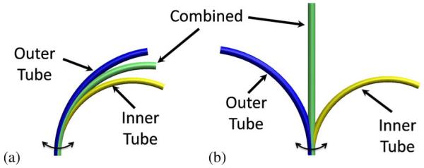
Balanced-stiffness tube pair. (a) Rotating tube pair with curvatures aligned. (b) Rotating-tube pair with curvatures opposed.
When either type of tube pair is used as a robot, the relative displacements of the tubes are produced by the application of forces and torques at the proximal end. When inertial effects are ignored, the magnitudes of the forces and torques are those necessary to deform the tubes from their combined minimum energy configuration and to overcome friction between the tubes.
Possible modes of tube deformation are bending, torsion, cross-section shear, and axial elongation. For the prediction of tip displacement, bending and torsion are the dominant contributors. The effect of bending on tube pairs has been described earlier. As will be derived in Section III, torsional twisting occurs whenever two curved tubes are rotated from the aligned configuration of Fig. 3(a).
The effect of torsional twisting is illustrated in Fig. 4. The relative twist angle varies from a maximum at the proximal end to a minimum at the distal end. Consequently, even if the initial curvatures of the two tubes are constant, the combined curvature will vary along the tubes’ length. This effect occurs for any two curved tubes regardless of their relative stiffness. The tubes of a balanced pair will both twist (as shown), while, for a stiffness pair that dominates, the more flexible tube will experience most of the twist. Only when one of the tubes is straight (zero curvature, as in Fig. 2) is there no bending-induced twist in either tube. There will be a small amount of twist due to friction in all cases.
Fig. 4.
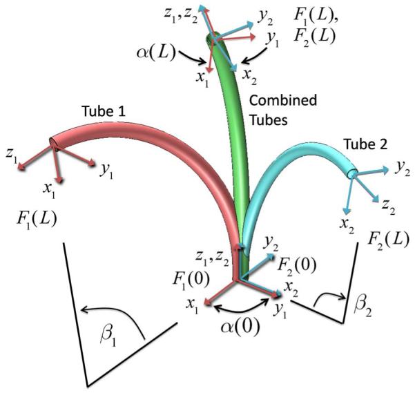
Effect of torsional twisting when two curved tubes are combined. Tube coordinate frames are denoted by Fi(s). The relative z-axis twist angle between frames α(s) varies from a maximum α(0) at the base to a minimum α(L) at the tip. The central angles βi are proportional to the precurvature and to the tube length L.
If a balanced pair is constructed from two tubes that possess the same stiffness and precurvature, each tube will twist the same amount but in opposite directions along their common length. Consequently, the pair will remain planar in shape. Furthermore, while their mutual curvature will vary somewhat along their length, it will be relatively constant for pairs that satisfy the torsion-bending stability constraint described next.
B. Constraints on Tube Curvature
The curvature of the individual tubes is limited by two main factors. First, to avoid permanent deformation of the robot, the maximum strain in the individual tubes should not exceed the elastic limit of the material. Second, the elastic interaction between torsion and bending can produce unstable tube configurations in which small perturbations in relative displacement at the tubes’ proximal end produce sudden large displacements at the distal end. Since these unstable motions could be dangerous, it can be desirable to prevent their occurrence by the imposition of limits on the curvature and length of the tubes.
1) Strain Limits
A simple planar geometric derivation yields an expression for strain ε due to bending from an initial curvature ui to a new curvature uf as a function of tube radius r [10]
| (1) |
Thus, the maximum strain occurs when (1) is evaluated at the outer radius. As suggested by the configurations of Figs. 2 and 3, the maximum expected change in curvature corresponds to straightening an initially curved tube. Equation (1) indicates that, for a given value of maximum strain, the maximum initial curvature is inversely proportional to tube radius. While the torsion that accompanies bending will increase strain from the value given by (1), it is an appropriate guideline for design.
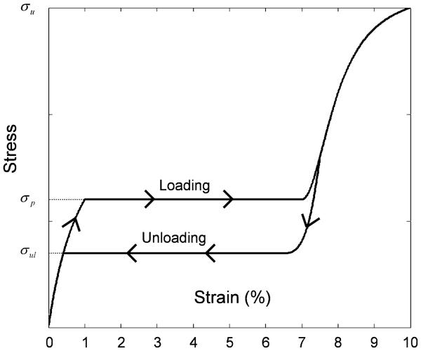
NiTi alloys and certain plastics are good material choices for concentric-tube robots since they can remain elastic for large strains and are also biocompatible. NiTi alloys, in particular, remain elastic for strains up to 6–8%; however, as shown in Fig. 5, they are linear only to 1–1.5% strain and exhibit hysteresis at higher strain. While a complete discussion is beyond the scope of this paper, the effect of this behavior on robot design can be summarized by taking into account its effect on tube pairs.
Fig. 5.
Stress versus strain curve for NiTi showing characteristic elastic loading and unloading plateaus.
Bending stiffness is given by EI in which E is elastic modulus, which corresponds to the slope of the stress–strain curve, and I is the cross-sectional moment of inertia. For a pair of tubes in which the maximum strain is less than the linear elastic limit, the ratio of bending stiffness is given by the ratio of cross-sectional moduli.
From (1), strain varies linearly with distance from the center of the tube. As the change in tube curvature increases, the cross section will transition from the linear elastic region to the stress plateau starting with the outer fibers. In this transition, the effective elastic modulus and, thus, bending stiffness decreases.
In a dominating-stiffness tube pair, the less stiff tube experiences higher strains, and therefore, its cross section transitions to the stress plateau first. This works in favor of the designer since it means that the effective stiffness ratio is larger than what is predicted from the ratio of cross-sectional inertias.
For balanced stiffness-tube pairs, the outer tube, which possesses a larger outer radius, will always start the transition to the stress plateau first given the same change in curvature. This is not an impediment to implementation of a balanced pair, however, and the effect can be incorporated in the kinematic model as needed.
2) Torsion-Bending Instabilities
The second limitation on tube curvature arises from the torsional twisting associated with rotating curved tubes. This effect will be derived in Section III; however, it is possible to provide a simple explanation here by reference to Figs. 3 and 4. As the tubes are rotated from their aligned configuration, the rotation angle at the distal end initially lags the rotation angle at the proximal end. If the lag is large enough that tip rotation fails to catch up as the proximal rotation angle approaches π [which corresponds to the configuration of Fig. 3(b)], the tubes will subsequently snap through this configuration to one in which the distal rotation leads the proximal value. The implications of instability for design are discussed next.
C. Robot Design
Based on the discussion of Section I, two desirable properties of a minimally invasive robotic instrument are as follows.
the ability to manipulate distal links independent of proximal links, i.e., to decouple the robot’s links;
the ability to navigate narrow curved passages and, if tissue is penetrated, exert minimal lateral forces.
A design strategy that provides these properties is encapsulated in the following four design rules and illustrated in Fig. 6.
Fig. 6.

Example five-tube robot design composed of three telescoping sections of variable, fixed, and variable curvature, respectively. Tube pairs comprising variable-curvature sections are rotated individually but extended simultaneously. Each section dominates the shape of those sections retracted inside it.
1) Telescoping Dominant Stiffness
The stiffnesses of the tubes are selected such that each telescoping section dominates all those sections extending from it. This is equivalent to a concatenation of dominating-stiffness tube pairs (recall Fig. 2). The result is that each telescoping section corresponds to a link whose shape and displacement are approximately kinematically decoupled from all other sections.
2) Fixed and Variable Curvature Sections
Each telescoping section behaves as a dominating (fixed curvature) or balanced (variable curvature) tube pair. Thus, the shape of each telescoping section is dominated by its outermost tubes and is of fixed curvature (if the outer tube dominates all inner tubes) or is of variable curvature (if the outer tube pair dominates all inner tubes). Tube curvatures are selected as per the constraints described in Section II-B.
3) Piecewise-Constant Initial Tube Curvatures
To avoid producing lateral motion or forces during telescopic extension, the order of extension must proceed from the proximal section to the distal one. In addition, the curvature of each section must be constant. By precurving each tube such that its curvature is piecewise constant, the combined telescoping curvature is also approximately piecewise constant. This is true even when torsion is considered. Telescopically extended fixed-curvature sections assume the shape of their precurvature since they dominate all inner tubes. In addition, as described at the end of Section I, a, stable variable-curvature section composed of balanced tubes remains planar and of almost-constant curvature.
4) Increasing Curvature From Base to Tip
While the shape of the proximal sections may be tightly constrained by the desired navigation path to the surgical site, it is often desirable to employ larger curvatures for the distal section(s). In this way, the proximal sections function as the links of a typical robot arm produce most of the tip displacement. The tightly curved distal sections function as the robot’s wrist to control most of the tip orientation as well as small displacements. Furthermore, since the distal sections’ tubes are comprised of the smaller diameter inner tubes, they can be given larger precurvatures without exceeding the elastic strain limit. Stable precurvature is limited, however, since the inner tubes are also the longest, and therefore, most prone to torsion-bending instabilities.
In summary, tube cross sections and initial curvatures are selected such that the robot behaves as a concatenation of kinematically independent dominating stiffness (constant curvature) and balanced stiffness (variable curvature) tube pairs. Each constantcurvature section has two kinematic input variables {l, θ} and contributes two DOFs that correspond to the extension length and rotation of the section (see Fig. 6). Each variable-curvature section has three kinematic input variables {θ1, θ2, l} and contributes three DOFs. The angles {θ1, θ2} control rotation and curvature of the section and l controls arc length (see Fig. 3).
The kinematic model developed in the next section provides the tools for computation of the displacements of the proposed telescopic concatenation of constant- and variable-curvature sections. It also dictates how closely these design goals can be achieved in practice.
III. Kinematic Modeling
In this section, we present a general kinematic model that includes bending and torsion for an arbitrary number of tubes whose curvature and stiffness can vary with arc length. (Note that this is more general than what is needed to model the designs proposed earlier.) Effects that are neglected include shear of the cross section, axial elongation, nonlinear constitutive behavior, friction between the tubes, and deformation due to external loading (including gravity). Note that while neglected, these effects may not be negligible but are beyond the scope of this paper.
For ease of exposition, the model is developed in several steps. First, coordinate frames and curvature are defined followed by a concise derivation of the torsionally rigid algebraic model. Next, the differential equation model for two torsionally compliant tubes is developed. Its analytic solution is given, and the torsion-bending stability condition is derived. Finally, the general multitube torsion-bending model is presented. The variables used in the paper are enumerated in Table I.
TABLE I.
Nomenclature
| i | Tube index, numbered from outer to inner. |
| s | Arc length measured from the proximal end of tubes. |
| L | Tube length. |
| r | Tube radius. |
| ε | Strain (scalar). |
| σl, σu | Loading and unloading stress (sealars). |
| E | Elastic modulus. |
| G | Shear modulus. |
| ν | Poisson’s ratio. |
| I | Cross section area moment of inertia |
| J | Cross section polar moment of inertia |
| F0(s) | Cross section reference frame (no twist). |
| Fi(s) | Cross-section material coordinate frame of ith tube. |
| Angle of z-axis rotation from cross section reference | |
| θi(s) | frame to cross section material frame. (θi(0) is kinematic input variable.) |
| li | Insertion distance of ith tube measured with respect to reference frame F0(0) (kinematic input variable.) |
| αi(s) | Relative z-axis rotation angle between cross section material frames, θi(s) − θ1(s). If no subscript, i = 2. |
| β i | Central angle produced by pre-curvature of ith tube. |
| Rz(α) | Rotation matrix for rotation of α about z-axis. |
| Three-component curvature vector of ith tube expressed in tube’s material coordinate frame. Also, angular strain rate per unit arc length. |
|
| v(s) | Three-component vector of linear strain rate per unit arc length. |
| Initial or pre-curvature vector of ith tube. | |
| mi(s) | Three-component bending moment vector of ith tube. |
| ni(s) | Three component shear force vector of ith tube. |
| Ki | Frame-invariant stiffness tensor of ith tube. |
| kix, kiy, Kiz | Diagonal components of stiffness tensor. |
| c | Constant given by (scalar). |
| nd(u|m), cd(u\m) |
Jacobi elliptic functions of scalar variables u and m. |
| K(m) | Complete elliptic integral of the first kind. |
A. Coordinate Frames and Curvature
In the remainder of the paper, subscript indices i = 1, 2, … , n are used to refer to individual tubes with tube 1 being outermost and tube n being innermost. Arc length s is measured such that s = 0 at the proximal end of the tubes. As shown in Fig. 4, material coordinate frames for each cross section can be defined as a function of arc length s along tube i by the definition of a single frame at the proximal end Fi(0), such that its z-axis is tangent to the tube’s centerline. Under the unrestrictive assumption that the tubes do not possess initial material torsion, the frame Fi(s) is obtained by sliding Fi(0) along the tube centerline without rotation about its z-axis (i.e., a Bishop frame [17]). As the tubes move, bend, and twist, these material frames act as body frames that track the displacements of their cross sections.
It is also useful to define a reference frame F0(s) (not shown) which displaces with the cross sections but does not rotate about its z-axis. When needed for clarity, superscripts will be used to indicate the coordinate frame of vectors and transforms.
As the ith tube’s coordinate frame Fi(s) slides down its centerline, it experiences a body-frame angular rate of change per unit arc length given by
| (2) |
in which (uix, uiy) are the components of curvature due to bending, and uiz is the curvature component due to torsion. A circumflex on a curvature component is used to designate the initial precurvature of a tube.
Curvatures transform between coordinate frames like angular velocities. Thus, with the definition of θi(s) as the z-axis rotation angle from frame F0(s) to frame Fi(s) and Rz(θi) as the corresponding rotation matrix, the curvature vectors transform as
| (3) |
B. Torsionally Rigid Model
An algebraic curvature model can be derived by the combination of three equations: 1) a constitutive model relates bending moments to changes in curvature of individual tubes; 2) the equilibrium of bending moments for the assembled tubes; and 3) a compatibility equation that relates the individual curvatures of the assembled tubes. These are described next.
1) Constitutive Model
When a tube with initial curvature is deformed to a different curvature , a bending moment is generated. On the assumption of linear elastic behavior, i.e., that strains remain in the linear elastic region of Fig. 5, the bending moment vector at any point s along tube i is given by
| (4) |
in which Ki is the frame-invariant stiffness tensor given by
| (5) |
and Ei is the modulus of elasticity, Ii is the area moment of inertia, Ji is the polar moment of inertia, and Gi is the shear modulus. While not explicitly noted, all variables in (5) can be functions of arc length in the derivations that follow.
2) Equilibrium of Bending Moments
In a concentric tube robot, forces and torques must be applied at the proximal end of the individual tubes to maintain any desired configuration. If no other wrenches are applied, the net force and torque applied to the tubes by the actuators is zero. Consequently, the net bending moment on every cross section is also zero
| (6) |
In this equation, all moments must be expressed in the same coordinate frame. Recall that the transformation of moments between collocated coordinate frames consists of a pure rotation [6]. Thus, they transform identically to curvatures as given by (3).
3) Compatibility of Deformations
On the assumption that the clearance between each pair of adjacent tubes is just sufficient to enable relative motion, all tubes must conform to the same final x–y (bending) curvature when assembled. On the assumption of torsional rigidity, the z-component of curvature is zero, and the compatibility equation is given by
| (7) |
Combining (3)-(7) yields an expression for the resultant curvature as a function of arc length s [10]
| (8) |
If the initial curvatures of the tubes are piecewise-constant curvature, (4) and (8) indicate that the bending moment and curvature are constant over each segment of the robot in which all of the tubes in that segment have constant initial curvature and stiffness. This is illustrated in Fig. 7. There is an implicit assumption here that, over negligible lengths at the boundaries of these segments, (4) and (7) are violated to produce discontinuities in curvature and bending moment.
Fig. 7.
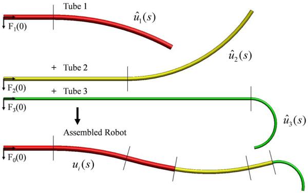
Three-tube example illustrating that torsionally-rigid model predicts tubes of piecewise-constant curvature combine to form a robot of piecewise-constant curvature.
Using this model, tubes of piecewise-constant curvature combine to form robots of piecewise-constant curvature. The tipcoordinate frame can be computed by analytic integration of the curvature of each constant-curvature segment and then concatenation of the resultant set of relative transformations [10]. While this model is computationally efficient, torsion must be included to obtain an accurate model as described next.
C. Torsionally Compliant Model for Two Tubes
In this derivation, we employ the special Cosserat rod model to account for torsional twisting of the tubes. The same results can be obtained by the use of the calculus of variations, as described in [16]. For clarity of presentation, the model is derived here for two tubes of constant curvature and length L.
It is convenient to define the relative twist angle α(s) between tubes as a function of arc length
| (9) |
where θi(s) is the z-axis rotation between frames F0(s) and Fi(s) at arc length s. Equilibrium of moments (6) can be written in the body frame of tube 1 as
| (10) |
To include torsional twisting, the compatibility equation (7) enforcing the coincidence of tube centerlines becomes
| (11) |
in which , and . This equation ensures that the tubes experience the same curvature in the plane of the cross section but allows different rates of torsional twist.
In the subsequent presentation, all tube variables are defined in their respective frame, and we omit reference to the frame. Thus, is written as u2(s).
1) Bending Curvature
Combining the moment equilibrium equation (10) with the constitutive model (4) and the compatibility equation (11) leads to an expression for the curvature of tube 2. On the assumption of circular cross sections, Rz(α) and Ki commute, yielding
| (12) |
The x and y components of this equation mirror those of the torsionally-rigid case and provide explicit algebraic equations for curvature as a function of initial curvature and twist angle α(s). The difference here is that twist angle α(s) is a function of arc length
| (13) |
| (14) |
2) Torsional Curvature
The z-component of (12) provides an expression for twist-angle rate
| (15) |
Here, we have used the fact that precurvature does not include torsional twist. To solve this expression, we need to be able to evaluate u2z.
We can obtain such an expression from the equilibrium equation of the special Cosserat rod model [18]-[20]. When time-dependent terms are set to zero, the body-frame equilibrium equations for a curved rod undergoing distributed loading of torque per unit length and force per unit length are given by
| (16) |
Derivatives are with respect to arc length along the rod s and are the bending moment and shear force vectors acting on the rod’s cross section. Here, and in the remainder of the paper, the square brackets on the vectors u and v denote the skew-symmetric form
| (17) |
Consistent with the previous notation, are the angular and linear strain rates per unit arc length. If one imagines sliding along a curved rod, these vectors can be interpreted as linear and angular velocities (twist velocities) with arc length that corresponds to time. Wrenches applied at either end of the rod enter the equations as boundary conditions.
Equation (16) can be interpreted as body-frame force and moment-equilibrium equations for a differential length ds of a curved beam or rod. The cross-product terms involving [u] are needed to account for rotation of the body frame along the length of the differential element.
This equation can be used to predict the shape and forces exerted when two or more precurved tubes are combined concentrically. Since we anticipate that bending and twisting will be the dominant forms of deformation of the tubes, we continue to assume that shear strain and axial strain are negligible. In (16), this results in vT = [0, 0, 1]. Furthermore, we assume that contact between the tubes is frictionless and that tubes can only exert distributed reaction forces, but not torques, on each other. As with the torsionally-rigid model, we assume that concentrated moments are generated over negligibly short lengths at discontinuities in precurvature and at the ends of tubes in order to satisfy compatibility [see (13) and (14)]. These moments are treated as boundary conditions in (16).
Since tube interaction is limited to distributed forces, τ = 0 in (16), and for each tube, it reduces to
| (18) |
To eliminate moments from these equations, we can use the constitutive model for moments (4) and its derivative with respect to arc length
| (19) |
In the derivative, we have taken Ki and to be independent of s for simplicity, but this is not necessary. Equation (18) can now be rewritten in terms of curvature
| (20) |
Recalling vi = [0, 0, 1]T and assuming equal bending stiffness in the x- and y-directions kix = kiy, the z-component of (20) provides an expression for the derivative of torsional-twist rate as a function of bending curvature
| (21) |
This simple equation indicates that the derivative of twist rate is given by the cross product between actual and initial bending curvature multiplied by the ratio of bending to torsional stiffness. For tubes, this ratio is given by
| (22) |
in which ν is Poisson’s ratio. By equilibrium of torsional moments, we need only integrate for u1z or u2z since
| (23) |
Equations (13), (15), and (21) comprise the set of equations that must be solved to compute curvature along the length of the tubes. Equations (15) and (21) are two first-order differential equations that can be equivalently described by a second-order equation in α. If we assume that the cross-sectional precurvature of both tubes is in the same direction (e.g., both in x direction or both in y direction) when α = 0, then the three equations reduce to the following simple expression for precurvature magnitudes and
| (24) |
This equation indicates that the second derivative of twist angle has a simple dependence on a constant c, given by Poission’s ratio multiplied by the initial tube curvatures.
Two boundary conditions are needed for the two state variables, (α, ) or (α, u2z). Since the tube angles at the proximal end θi(0) are the kinematic input variables
| (25) |
In addition, the torsional bending moment at the distal end of each tube is zero
| (26) |
This yields a second boundary condition
| (27) |
This is a two-point boundary value problem that can be integrated analytically, as shown next.
D. Analytical Solution for Two Tubes
The differential equation (24) governing the twist of two constant-curvature tubes has two trivial equilibrium solutions
| (28) |
These correspond to the situations in which the cross-sectional curvature vectors of the tubes have the same and opposite directions, respectively (see Fig. 3). In neither case is an external torque needed to maintain the configuration. One can guess, however, that the solution α(s) = π is not a minimum-energy solution for the kinematic input value α(0) = π, and thus, it is likely that additional solutions to (24) share the initial condition α(0) = π. To study solution multiplicity, we seek an analytic solution to (24).
1) Analytic Integration
To integrate by separation of variables, we use and write
| (29) |
in which and a are variables of integration. This results in the following expression for :
| (30) |
Evaluating this equation using the boundary condition and substituting the result in (30) yields
| (31) |
Separation of variables can be used again to obtain
| (32) |
In (32), the sign is selected to match the sign of the integration interval sgn (α(s) − α(0)). Recognizing (32) as an incomplete elliptic integral of the first kind, we desire an expression for the upper limit of integration α(s). This can be obtained in terms of Jacobi elliptic functions by a variety of methods, including converting the integral of (32) to standard form or by assuming a solution and showing that it satisfies (31). This results in
| (33) |
in which nd (u|m)and cd (u|m) are Jacobi elliptic functions [21]. See Appendices A and B for a brief description of these functions, as well as a proof that (33) satisfies (24).
Equation (33) expresses relative twist angle in terms of the twist angle at the distal end. We are specifically interested in the value at the proximal end since it is the kinematic input α(0) = θ2(0) − θ1(0)
| (34) |
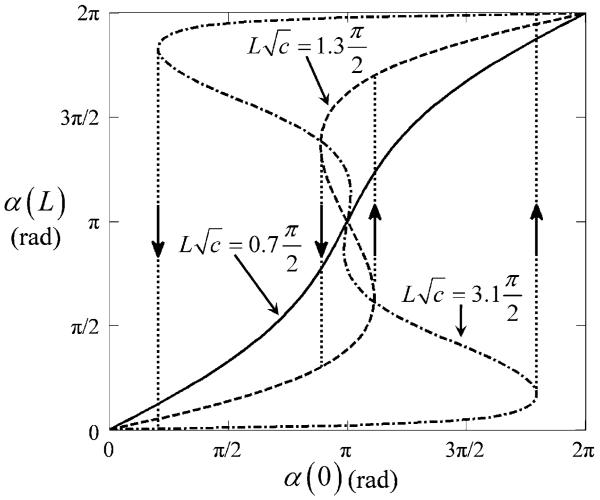
These expressions involve a single dimensionless parameter . Fig. 8 plots (34) for several values of this parameter.
Fig. 8.
Relative twist angle of tubes at base versus tip for three values of . Only the curve with exhibits stable rotation.
2) Solution Multiplicity
It can be seen from the figure that at least one value of α(L) exists for each value of α(0) ∈ [0, 2π], but it is also apparent that there can be multiple solutions. Solution multiplicity produces sudden changes in tube twist in response to incremental changes in the kinematic input α(0). These “snap through” instabilities are indicated as dotted lines in the figure and correspond to the tubes traversing between minimum energy branches of the curve.
To determine the dependence of the instability on the parameter Lc1/2, we count the solutions for α(L) given α(0) = π. Identical results are obtained using either the sine or cosine equation of (34). The sine equation reduces to
| (35) |
Since dn (u|0) = 1, (35) always has at least one solution {α(0), α(L)} = {π, π} corresponding to the case of zero twist along the tubes’ length. To determine when additional solutions exist, we use the identity [21]
| (36) |
and note that dn is periodic in its first argument with period 2K(m). Here, K(m) is the complete elliptic integral of the first kind, which is a monotonically increasing function of m with K(0) = π/2 and K(1) = +∞. Combining (35) and (36) results in
| (37) |
This equation has no solutions for . For , the n = 1 solution is identical to the original solution {α(0), α(L)} = {π, π}. For , one new solution to (37) exists. Since m = sin2 (α(L)/2), this yields two new solutions . As seen in Fig. 8, these solutions are symmetric about α(L) = π. Similarly, yields four solutions to (37).
The dimensionless parameter is very important from a design perspective. The model predicts stable behavior for tubes satisfying
| (38) |
As this parameter increases, however, additional solutions exist which lie on unstable branches of the relation. The critical values of α(0) at which “snap through” occurs correspond to the extrema of α(0) adjacent to the n =1 solution of (37).
A geometric interpretation of (38) can be obtained by noting that
| (39) |
in which β1 and β2 are the central angles swept out by the initial curvatures of the tubes, as shown in Fig. 4. Thus, if two frictionless tubes of the same length L possess initial curvatures with central angles β1 and β2, they can be combined and rotated at their proximal end without instability as long as the geometric mean of their central angles satisfies
| (40) |
Assuming that ν ≈ 0.3 and that the tubes have the same initial curvature, their maximum stable central angle is limited to about 1.38 rad (79°). This equation must be modified and the maximum central angle reduced if the curved sections are located at the distal ends of straight transmission lengths.
E. General Model for an Arbitrary Number of Tubes
The equations of Section III-C can easily be extended to include any number of tubes of arbitrary stiffness and initial curvature [16]. For n tubes, the equations can be written in terms of 2n − 2 state variables {αi, uiz}, i = 2, … , n. The relative twist angles are defined by
| (41) |
where θi(s) is the angular displacement of the ith tube at arc length s. The resulting equations are
| (42) |
and can be directly compared to those for two tubes given by (13), (15), and (21).
As before, half of the boundary conditions are obtained from the kinematic input variables θi(0)
| (43) |
The remainder are defined by the torque applied at the distal ends of the tubes. Assuming no external torque, the torsional bending moments and, thus, curvature are zero at this location
| (44) |
Equations (42)-(44) are easily applied to any combination of precurved tubes—regardless of whether or not the tubes follow the design guidelines of Section II-C. The stiffness and precurvature of each tube can be an arbitrary function of arc length. This includes discontinuities in both stiffness and precurvature. Consequently, there is no need to subdivide the domain during integration over a telescoping arrangement of tubes. Distal to the physical end of each tube, its stiffness and curvature can be defined as zero. Details of the numerical solution are presented next.
IV. Closed-Loop Position Control
Tool-frame position control involves solving the forward and inverse kinematic problems at real-time rates. The forward kinematic model (42)-(44) presents a challenge in this regard since it is both a nonlinear second-order differential equation, and it has split boundary conditions. Furthermore, these equations yield curvature as a function of arc length. Curvature must be integrated once more to yield tip-frame orientation and a second time to obtain tip-frame position.
To achieve a real-time implementation, the approach taken here is to precompute the model’s forward-kinematic solution over the robot’s workspace and then to approximate it by a product of truncated Fourier series. The inverse kinematic solution is solved at each time step using a root-finding method applied to the functional approximation. These techniques are described in the following sections.
A. Forward-Kinematic Functional Approximation
To solve (42)-(44), we note that robot shape is independent of rigid-body translation and rotation. Since rotation or translation of all tubes simultaneously produces rigid-body motion, the number of independent kinematic inputs can be reduced by two. Given the form of (42), we choose the rotation and translation of the first tube θ1 and l1 as references to measure all tubes’ angles and linear displacements. Thus, the reduced set of kinematic input variables is {α2−n(0), l2−n} = {αi(0), li}, i = 2, … , n, and the desired output is the tip-frame position and orientation relative to the base g1(α2−n(0) l2−n). Here, subscript 1 indicates that the displacement is for the reference values of θ1 = l1 = 0. The transformation for nonzero values is given by
| (45) |
To precompute the forward-kinematic solution over a grid of kinematic input values, it is convenient to define the grid at the robot’s tip in terms of {αi(L), li}, i = 2, … , n and therefore solve (42) and (44) as an initial value problem by integrating backward in arc length from L to 0. This yields the curvature along the robot as well as the input twist angles αi(0), i = 2, … , n. Curvature can then be integrated along the robot’s length to yield tip position and orientation relative to the base g1(α(0), l), as defined earlier. Integrating curvature is analogous to integrating body-frame twist velocity. A variety of numerical integration methods are available that preserve group structure on SE(3) [22], [23].
A dense discretization of {α2−n(0), l2−n} yields a large data set of g1(α2−n(0), l2−n). While one approach is to store this data as a lookup table, functional approximations offer reduced storage requirements at modest computational cost. Since the input variables have a periodic effect on the tip frame, each of the tip-frame coordinates can be modeled using a product of truncated Fourier series.
Define a scalar Fourier series H of order q as
| (46) |
in which , , where the asterisk indicates complex conjugate. We model each of the tip coordinates in p1 = [x1, y1, z1]T using a product of series in the form of (46). For example, assuming n tubes that can be rotated and translated and using the same order series for all input variables, x1 is of the form
| (47) |
in which the linear displacement variables li are scaled by appropriate wavelength parameters λi.
Tip orientation can be modeled in a similar fashion. For example, for the 5-DOF robot used in the experiments, roll angle is undefined and a tangent vector can define orientation t1 = [tx1, ty1, tz1]T with components modeled by (47).
Multiplying out the product expansion for each component of tip position and direction produces sets of unknown constant coefficients that can be estimated using linear least squares from the dataset g1(α2−n(0), l2−n). The resulting approximation is denoted as , and it can be used in (45) to produce the approximated forward kinematic solution .
B. Real-Time Inverse Kinematics
Given the desired tip frame , the inverse-kinematics problem can be posed as a root-finding problem. The desired joint values correspond to the zero of a scalar- or vector-valued function representing the distance between the actual and desired tip frames. One example of is the twist vector corresponding to the screw motion between and . In this context, the standard Jacobian-inverse approach is an online implementation of Newton’s root-finding method.
For the 5-DOF robot used in the experimental implementation described next, tip-frame roll angle is undefined, and therefore, the function is selected as
| (48) |
Here, tip position is given by p0 and tip-tangent direction by unit vector t0. The scaling factor γ is given by the ratio of maximum tip-position error to maximum orientation-angle error
| (49) |
Root finding is accomplished using the Gauss–Newton method. The method requires the Jacobian of (48) with respect to the joint variables. This can be evaluated numerically using additional function evaluations of (48) or computed from the analytic form of the Jacobian. The latter is easily obtained since the partial derivatives of (47) with respect to the joint variables have the same functional form as (47).
The number of iterations needed to converge to the inverse solution depends on the initial magnitude of (48). In teleoperation, the current joint values and tip location can be used to initiate root finding for the next time step. Thus, the maximum magnitude is usually small and can be estimated from the desired tip-motion bandwidth and controller-cycle time. For example, a 10-mm-amplitude sinusoidal tip displacement at 10 Hz has a maximum displacement of less than 1 mm during a 1 kHz control cycle. Consequently, the algorithm typically converges within a controller time step. For those cases when convergence is not obtained within a control cycle, motion is still well behaved since the implementation is such that error decreases with each iteration. As described next, our current unoptimized implementation can compute up to eight iterations during the 1 ms time step of our 1 kHz controller.
V. Experimental Model Evaluation
A sequence of experiments was performed to compare the predictions of the torsionally rigid and torsionally compliant models. The experiments were performed in the context of the robot depicted in Fig. 9 that is composed of the three tubes shown in Fig. 10. The outer pair is of the balanced stiffness, variable curvature type (see Fig. 3). Its kinematic input variables consist of tube rotation angles θ1, θ2, and a single translation variable for the pair l1 = l2. The innermost tube is dominated by the outer pair (see Fig. 2) and its kinematic variables are θ3, l3. The five kinematic inputs are used to control the robot’s tip position and tangent direction.
Fig. 9.
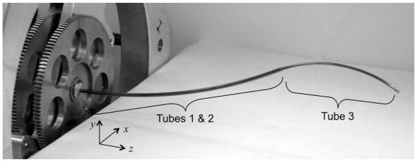
Three-tube concentric-tube robot.
Fig. 10.
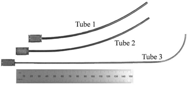
Tubes comprising the robot. Tubes 1 and 2 form a variable-curvature balanced pair that dominates tube 3. Ruler shows units in millimeters.
The diameters of the three tube sizes used in all of the experiments are given in Table II. To solve the forward kinematics, (42) requires the relative stiffness of the tubes as well as the ratio of bending to torsional stiffness for each tube. Given that the tubes are of the same alloy and were processed similarly, the relative stiffness of the tubes should be computable as the ratio of moments of inertia. Stacking the tolerances for inner and outer diameters of tube pairs, however, produces large variations in stiffness ratio. Instead, calibrated stiffness ratios were computed from (8) by measuring the individual tube precurvatures and the pairwise combined curvature for αi(s) = π using a camera-measurement system (Vision Appliance, Dalsa, Inc.). Note that this equation is valid for torsionally compliant tubes in this configuration if they satisfy (38). The ratio of bending to torsional stiffness is given by (22) and was computed using a value of ν = 0.3.
TABLE II.
Tube Stock Used in Experiments
| Tube | 1 | 2 | 3 |
|---|---|---|---|
| Outer Diameter (mm) | 2.77+/−0.01 | 2.41+/−0.01 | 1.85+/−0.01 |
| Inner Diameter (mm) | 2.55+/−0.01 | 1.97+/−0.01 | 1.65+/−0.01 |
For these tube dimensions, tip deflection due to gravity (<0.3 mm) was within the measurement error of the camera system (±0.5 mm), and therefore, its effects were neglected in the experiments.
For clarity, the modeling error associated with the outer pair of tubes is considered separately in the first section below. The following section characterizes the error associated with the kinematic variables of the third tube {θ3, l3}. Finally, total error for the three tubes is reported for a range of configurations in the robot’s workspace.
A. Rotation of Balanced Tube Pairs
To validate the behavior predicted in Fig. 8, tests were performed on three tube pairs (labeled A, B, and C) of identical cross sections (Tubes 1 and 2 stock) and length but of different precurvatures, as shown in Fig. 11 and described in Table III. Each tube is glued into a collar as shown and mounted in the motor-drive system, as shown in Fig. 12 and described in [13]. Motor-positioning accuracy is better than 0.1°. Equation (34) must be adjusted to relate α2(0) measured at the proximal end of the curved portion of the tubes to the relative angle measured by the motor encoders at the tube collars α2m. This is given by
| (50) |
Fig. 11.
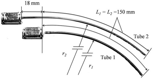
Dimensions of tube pairs.
TABLE III.
Balanced-Pair Tube Parameters
| Tube Pair | A | B | C |
|---|---|---|---|
| r1 (mm) | 242 | 154 | 93 |
| r2 (mm) | 260 | 154 | 93 |
|
Calibrated stiffness ratio
(tube 2 / tube 1) |
1.28 | 1.53 | 1.53 |
Fig. 12.
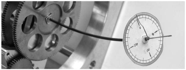
Tube pair showing graduated disk, twist pointer, and tangent pointer.
Unlike (34), this computation requires the stiffness ratio of the tubes. This ratio was computed using the method described earlier, and as reported in Table III, it was found to differ between tube pairs.
To measure the twist at the distal end of the tubes α2(L),a circular graduated disk was attached over the last 2 mm of the outer tube (see Fig. 12). A 2-cm-long straight wire was attached to the tip of the inner tube to enable measurement of the tip tangent direction. A twist pointer was attached perpendicular to this wire adjacent to the disk for twist measurement and zeroed for the configuration in which the curvature of the tubes is aligned. The error in measuring tip angle was estimated to be ±2°.
1) Torsional Twisting
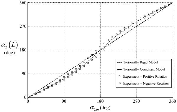
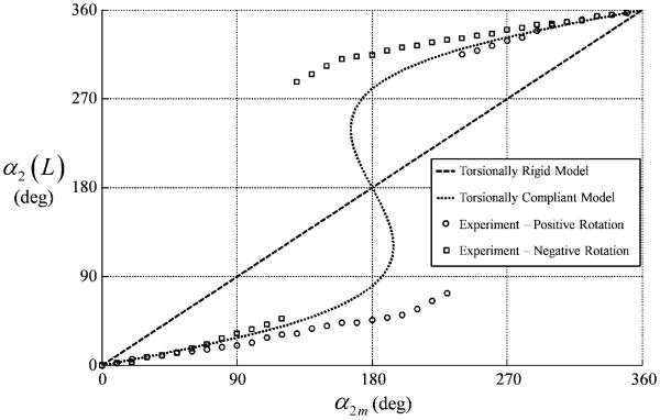
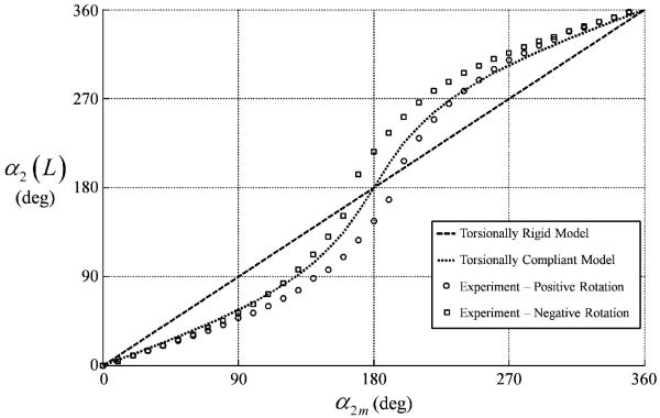
Figs. 13-15 compare the torsionally-rigid and -compliant models with experiment for the three tube pairs. The torsionally-rigid model is a line of unit slope while the torsionally-compliant model obtained from (34) and (50) predicts s-shaped curves. Experimental data was collected by rotating the tube pairs quasistatically through a complete revolution in the positive and negative directions. This data produced an envelope of the possible reachable values of (α2m, α2(L)). The envelope is due to unmodeled phenomena. While not shown, it was demonstrated experimentally that the entire interior of the envelopes in Figs. 13 and 14, including the point (α2m, α2(L)) = (π, π), is reachable and stable. In contrast, there are stable and unstable portions of the envelope in Fig. 15.
Fig. 13.
Tip versus motor twist angle for tube pair A.
Fig. 15.
Tip versus motor twist angle for tube pair C.
Fig. 14.
Tip versus motor twist angle for tube pair B.
These figures clearly demonstrate the predictive capability of the torsionally compliant model in comparison with the rigid model. They also validate that twist, and thus, deviation from the rigid model increases with increasing curvature. Stable rotation is also successfully predicted for the tube pairs of Figs. 13 and 14.
In each direction of rotation, α2(L) initially lags α2m, but, in agreement with the torsional model, α2(L) subsequently increases faster than α2m such that α2m = α2(L) = π is a valid solution. In contrast, Fig. 15 exhibits a “snap-through” instability. In this case, the lag in α2(L) continues beyond α2m = π until α2(L) suddenly transitions through π to reach the other stable branch of solutions.
In contrast to both models, however, experiment shows that every nonzero value of α2m (excluding the unstable region of Fig. 15) can produce the range of values of α2(L) that lie inside the experimental envelope. The specific value achieved depends on the history of motion of α2m. Identifying the physical origin of this phenomena and modeling it is beyond the scope of this paper. For the purpose of evaluating tube-tip location error below, the average tip location is computed from the boundaries of the envelope.
2) Tip-Location Error
While Figs. 13-15 show that torsional twisting of the tubes does occur, they do not reveal the relative error of the models in predicting tube-tip position and tangent direction. These quantities were measured using a stereo-camera system (Vision Appliance, Dalsa, Inc.) during the twist experiments described earlier. The tangent direction at the tip was computed from the coordinates of the points at the base and tip of the tangent pointer of Fig. 12. To evaluate model error, the average location of the tip is computed from the two boundaries of the envelope and compared to the predicted value.
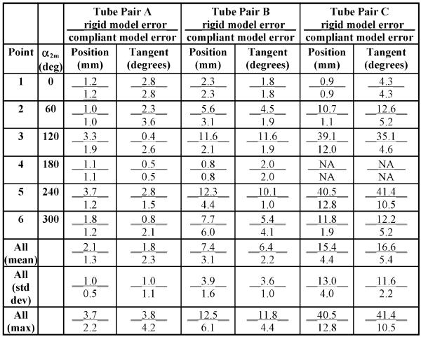
Table IV reports position- and tangent-direction error for the three sets of tubes at six values of α2m. The mean, standard deviation, and maxima are also reported for the complete datasets of Figs. 13-15. To visualize the workspace of the tube pairs, Fig. 16 depicts the torsionally rigid solutions for tube pair B at the six values of α2m reported in the table.
TABLE IV.
Tube-Pair Tip Position and Tangent Error
|
Fig. 16.
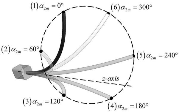
Tube pair B workspace. Depicted configurations are computed using the torsionally rigid model.
As can be seen from Figs. 13 and 14 and Table IV, the torsionally rigid and compliant models are in agreement for stable tube pairs at α2m = {0, π, 2π}. For those values of α2m at which torsional twisting is largest α2m ≈ {120, 240}°, the model predictions diverge significantly, and as shown in Table IV, the torsional model is much more accurate. For example, at α2m = 240°, the rigid and torsional-modeling errors of tube pair B are 12.3 versus 4.4 mm in position and 10.1 versus 1.0° in tangent direction.
The effect of tube curvature on the models can be observed by comparing the increasing divergence between the models across Figs. 13-15. The effect on model error can be seen by comparing the columns of the three tube pairs in Table IV. While error grows with increasing curvature for both models, the torsionally compliant model is substantially more accurate.
Figs. 13 and 14 also show how the magnitude of the experimentally observed, but unmodeled, twist envelope varies from zero when α2m = {0, 2π} to a maximum when α2m = π. This envelope is the major source of error observed in the compliant model.
B. Rotation and Translation of Tube 3
The models were evaluated for tube 3 inserted inside tube pair B of Table III. For convenience, the parameters of all three tubes are given in Table V. As depicted in Fig. 10, the proximal section of the third tube is straight while its distal section is of constant curvature. As noted in the table, the curved portion of Tube 3 was found to have a lower measured stiffness than its straight portion.
TABLE V.
Tube Parameters
| Tube | 1 | 2 | 3 |
|---|---|---|---|
| Outer Diameter (mm) | 2.77+/−0.01 | 2.41+/−0.01 | 1.85+/−0.01 |
| Inter Diameter (mm) | 2.55+/−0.01 | 1.97+/−0.01 | 1.65+/−0.01 |
|
Sections of constant pre-
curvature listed base to tip (length, mm; radius, mm) |
(l=150; r=154) | (l=18; r=∞) (l=150; r=154) |
(l=186; r=∞) (l=57; r=35) |
|
Calibrated stiffness (relative
to Tube 1) |
1 | 1.53 | 0.21 (straight) 0.07 (curved) |
|
Maximum % strain to
straighten curved section |
0.57 | 0.46 | 2.64 |
The workspace generated by the translation and rotation of the third tube relative to the outer pair is illustrated in Fig. 17. Since the outer pair is substantially stiffer, tube 3 does not deform the outer pair very much as it rotates with respect to them, and thus, its tip traces out a path that is close to circular.
Fig. 17.
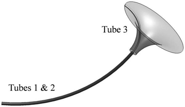
Workspace generated by rotating and translating tube 3 with respect to the outer pair.
Twist in the third tube was experimentally measured with α2m = 0 for three extension lengths l3 = 0, 30, 57 mm, corresponding to the tube being fully retracted, partially extended, and fully extended. Results are shown in Fig. 18, together with the predictions of the torsionally compliant model. As before, data were recorded for both directions of rotation revealing an envelope of reachable, stable solutions.
Fig. 18.
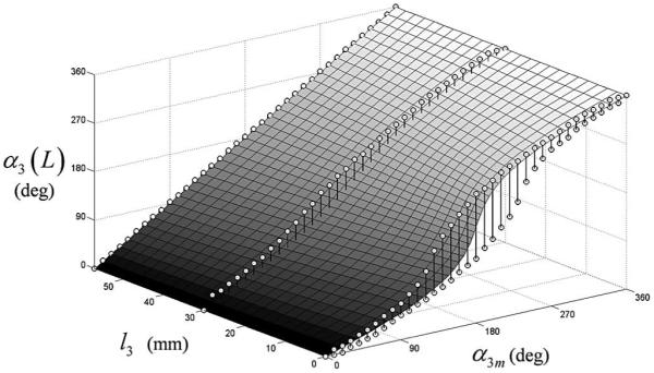
Tube 3 tip twist angle versus motor twist angle and extended length for α2m = 0. Circles are experimental data points. Surface denotes prediction of torsionally compliant model.
In agreement with Fig. 18, the torsionally compliant model predicts that, for any fixed values of α2m and α3m, twistin the third tube should increase from zero, when its curved section is fully extended beyond the tip of the outer tube pair (l3 = 57 mm) to a maximum, when its curved length is fully retracted inside the curved outer pair (l3 = 0 mm). Thus, the rigid and compliant models are in agreement at full extension but predict substantially different results as the inner tube is retracted into the outer pair.
C. Modeling Error Over 3-Tube Robot Workspace
This section reports overall model error for the robot of Fig. 9 using the tubes of Table V. As described earlier, the kinematic input variables associated with deformation of the tubes are {α2m, α3m, l3}. The workspace associated with these variables can be envisioned by combining the motion of the outer tube pair in Fig. 16 with that of the inner tube depicted in Fig. 17. Robot tip position and tangent direction were measured at 128 configurations in this workspace for the following values of {α2m, α3m, l3}:
| (51) |
The two values of l3 correspond to the curved portion of the third tube being fully retracted and half extended from the outertube pair. To take into account the effect of motion history on tip location, two measurements were taken at each configuration corresponding to positive rotations of α2m and both positive and negative rotations of α3m. Values associated with negative rotations of α2m were calculated assuming symmetry. Model error was computed at each configuration using the average experimental tip location calculated from the two measured and the two calculated locations.
Table VI compares tip position and tangent errors for the torsionally-rigid model (8) and the torsionally compliant model (42)-(44). The inclusion of torsion substantially reduces the mean, variance, and maximum of the position error. As can be inferred from Table IV, substituting more highly curved tubes would produce a larger difference between the models.
TABLE VI.
Robot Tip Error
| Rigid Model Error |
Compliant Model Error |
Error Reduction | ||||
|---|---|---|---|---|---|---|
| Position (mm) |
Tangent (deg) |
Position (mm) |
Tangent (deg) |
Position (mm) |
Tangent (deg) |
|
| Mean | 8.4 | 10.8 | 4.2 | 8.6 | 4.2 | 2.2 |
|
Std.
Dev. |
4.7 | 5.4 | 2.0 | 4.1 | 2.7 | 1.3 |
| Max. | 18.6 | 29.8 | 8.3 | 20.2 | 10.3 | 9.6 |
The largest contributor to error in the torsionally compliant model is the experimentally observed history dependence of tube twist. It is likely that this dependence is due to one of the modeling simplifications, e.g., ignoring cross-section shear, axial elongation, nonlinear elasticity, and friction.
Additional sources of error include uncertainty in tube parameters and the finite clearance between tubes 2 and 3 at the distal end of tube 2.
VI. Real-Time Position Control
To demonstrate real-time implementation of the compliant model, as described in Section IV-A, a teleoperation system using the robot shown in Fig. 9 and tube properties of Table V was implemented using the controller shown in Fig. 19. The system includes a master arm comprised of a PHANTOM Omnihaptic device (Sensable Technologies, Inc.), a slave arm consisting of the concentric tube robot, and master and slave controllers. In the case shown and described here, the robot consists of the three tubes shown in Fig. 10 and possesses 5-DOFs. As described earlier, the outer pair is of the balanced stiffness, variable-curvature type (see Fig. 3). Its kinematic input variables consist of tube rotation angles θ1, θ2, and a single translation variable for the pair l1 = l2. The innermost tube is dominated by the outer pair (see Fig. 2) and its kinematic variables are θ3, l3. The five kinematic inputs are used to control the robot’s tip position and tangent direction.
Fig. 19.
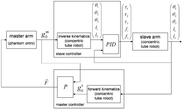
Teleoperator block diagram.
In Fig. 19, the slave controller receives the position and tangent direction of the tip of the master arm (represented by ) and calculates the inverse kinematics of the concentric-tube robot using the method described in the preceding section. Then, a set of PID controllers calculate the torques/forces applied to the tubes of the robot. The master controller reads the tube configuration of the robot and calculates the position and tangent vectors of its tip. The force feedback provided to the master is governed by a proportional-control law based on the Cartesian position error between the master- and slave-tip positions.
The teleoperator system of Fig. 19 is implemented by a multithreaded process under Windows 2000. While Windows 2000 does not natively support hard real-time scheduling, it does support soft real-time scheduling with a time-critical thread priority. When used appropriately, a time-critical thread may be used to maintain a regular 1 kHz update rate with sufficiently low timing variations to be used for closed-loop control. For this particular controller, the slave mechanism bandwidth is less than 10 Hz, and therefore, soft real-time implementation of a 1 kHz control loop was more than sufficient.
The process includes two time-critical user-mode threads running at 1 kHz that implement the controllers and an application thread that updates a graphical user interface (not shown). One of the time-critical threads executes the PID controller of the slave arm, and the other executes the master controller and inverse-kinematics block of the slave controller. The separation of threads eases integration between the master with its IEEE-1394-based interface and the slave controlled through a Quanser Q8 data acquisition board with its real-time input–output subsystem support accessed through the hardware in the loop software development kit (HIL SDK).
A. Forward Kinematic Model
The method of Section IV-A was used to arrive at a functional approximation of the forward-kinematic model. Removing the rigid-body degrees of freedom, the reduced set of kinematic input variables is given by {α2, α3, l3}. Solving (42) and (44) as an initial value problem, the resulting curvature was integrated backward in arc length from L to 0 to get g1(α2(0), α3(0), l3) for a uniform 40 × 40 × 40 grid of {α2(L), α3(L), l3}. This dataset was used to construct a second-order product series (47) for each component of the position and tangent vectors using a wavelength of . The resulting functional approximations, where each is defined by 125 constant coefficients, were evaluated against a second dataset constructed using grid values midway between those of the original set. In this evaluation, the average tip-position error was 0.025 mm (0.1 mm maximum), and the average tip-tangent error was 0.02° (0.06° maximum). This approximation error is insignificant in comparison to modeling error.
B. Inverse-Kinematic Model
Inverse kinematics were implemented, as described in Section IV-B. Tube lengths and precurvatures limit maximum tip position and orientation errors to approximately 200 mm and π rad, respectively. For convenience of interpretation, the scaling factor of γ = (180 mm)/(π rad) was selected yielding a tangent error magnitude in degrees.
Our current unoptimized implementation of the Gauss–Newton method can perform eight iterations in 0.5 ms; however, convergence to the accuracy of the functional approximation is usually achieved in five or fewer iterations. This fits easily within the 1 ms cycle time of our controller.
In addition, the inverse kinematic implementation enforces continuity of the inverse solution and enforces joint limits on the tube extension variables l1 = l2 and l3.
C. Results
Performance of the teleoperation system was evaluated for a task that consisted of touching a sequence of nine 2-mm-diameter beads embedded in the faces of three dodecahedral dice suspended on posts, as shown in Fig. 20. This task requires the operator to control both the tip position and tangent direction to contact the beads. As shown in the accompanying video, teleoperation is smooth and responsive.
Fig. 20.
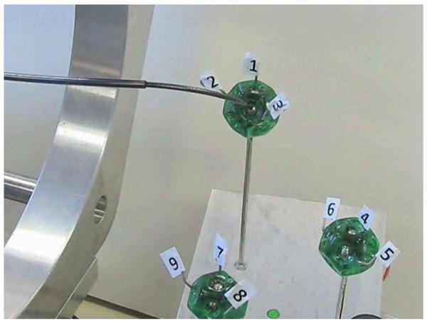
Teleoperated real-time position control task. Touching sequence of nine silver beads embedded in dice involves controlling both position and tangent direction of robot tip.
Since the inverse kinematic solver converges within each time step, trajectory-following error is due to kinematic-modeling error and drive-system bandwidth limitations. Steady-state control error is due only to modeling error.
VII. Conclusion
Concentric tube robots are a novel technology that has broad potential in minimally invasive surgery. The design principles presented in Section II provide the tools to produce concentrictube robots that exhibit stable motion, possess kinematically decoupled links, and are capable of snaking through curved passages. The authors are currently using the principles described in this paper to design such robots for surgery inside the beating heart and inside the brain.
The new torsion-flexure kinematic model of Section III is completely general. It can be used to compute the resultant shape of any number of tubes of arbitrary cross section and precurvature while also predicting unstable tube configurations. Furthermore, it is substantially more accurate than prior models with its comparative accuracy increasing with both tube length and curvature. Using only geometric and mechanical parameters obtained from simple static measurements, the new model reduced tip-position error by 50% to 4.2 ± 2.0 mm for a 200-mm-long robot. The major remaining source of error is an experimentally observed dependence on motion history that is the subject of future research.
While the kinematic model is a two-point boundary-value differential equation, Section IV provides a technique for pre-computing an accurate functional approximation. This section also details an online root-finding method for implementing real-time position control. Unoptimized control code running on a PC was easily able to compute the three-tube inverse-kinematic solution at 1 kHz rate. Thus, both analytically and numerically, the approach provides the capacity for extension to robots with greater numbers of tubes. It can also be easily adapted to future kinematic models that include currently neglected effects such as friction and nonlinear constitutive behavior.
Acknowledgments
This work was supported in part by the National Institutes of Health under Grant R01HL073647 and Grant R01HL087797 and by the Wallace H. Coulter Foundation. This paper was presented in part at the IEEE International Conference on Robotics and Automation, Kobe, Japan, May 2009. This paper was submitted in part to the forthcoming IEEE International Conference on Robotics and Automation, Anchorage, AK, May 2010.
Biography

Pierre E. Dupont (M’99–SM’03) received the B.S., M.S., and Ph.D. degrees in mechanical engineering from Rensselaer Polytechnic Institute, Troy, NY, in 1982, 1984, and 1988, respectively.
From 1988 to 1990, he was with the School of Engineering and Applied Sciences, Harvard University, Cambridge, MA, as Postdoctoral Fellow. He subsequently was with Boston University, Boston, MA, where, until recently, he was a Professor of mechanical engineering and biomedical engineering. He is currently with the Children’s Hospital Boston and Harvard Medical School, Boston, as Director of Pediatric Cardiac Bioengineering and is engaged in the development of instrumentation and imaging technology for minimally invasive surgery.
Prof. Dupont has served on many committees of the IEEE Robotics and Automation Society, including the Administrative Committee. He has also served as an Associate Editor for the Transactions on Robotics and Automation and the Transactions on Robotics. He is currently an Associate Vice President for Publications and a member of the Management Committee of the IEEE Transactions on Haptics.

Jesse Lock received the B.A. degree in english from Amherst College, Amherst, MA, in 1997 and the M.D. degree from Albany Medical College, Albany, NY, in 2002. He is currently working toward the Ph.D. degree in biomedical engineering with Boston University, Boston, MA.
He spent a year of clinical pediatric research at Stanford University, Stanford, CA. He completed his residency in pediatrics at Oregon Health Sciences University, Portland, in 2005. He subsequently enrolled in a transitional engineering program at Boston University. His research interests include robotics and medical devices as they pertain to pediatric health care.
Dr. Lock is a recipient of a National Institutes of Health National Research Service Award Fellowship.

Brandon Itkowitz received the B.S. degree in computer systems engineering and the M.S. degree in electrical engineering from Boston University, Boston, MA, in 1999 and 2008, respectively.
From 1999 to 2008, he was with SensAble Technologies, Woburn, MA, as a Lead Software Engineer. He has two patents pending related to the OpenHaptics Toolkit. He is currently with the Applied Research Group of Intuitive Surgical, Inc., Sunnyvale, CA, as a Senior Software Engineer. His research interests include human–computer interaction, surgical robotics, haptic rendering, computer graphics, and computational geometry.

Evan Butler (S’08) received the B.S. degree in physics in 2007 from Boston University, Boston, MA, where he is currently working toward the M.S. degree in mechanical engineering with special focus on control systems.
His research interests include medical robotics and intelligent flight-control systems.
Mr. Butler is a recipient of the National Aeronautics and Space Administration Graduate Students Research Projects Fellowship.
Appendix A
Following the presentation of [21], the Jacobi elliptic functions can be defined in terms of the integral
| (52) |
with u, . The following three Jacobi elliptic functions can be used to generate the remaining nine functions:
| (53) |
The functions used in the paper and Appendix B are
| (54) |
Since Jacobi elliptic functions involving any real values of m can be expressed in terms of Jacobi-elliptic functions with 0 ≤ m ≤ 1, it is sufficient to consider m in this interval. Using the terminology of [21], m and m1 are referred to as the parameter and complementary parameter, respectively, and
| (55) |
Additional insight into the functions of (54) can be gained by evaluating them at the limiting values of the parameter m
| (56) |
In the derivation next, the following formulas for derivatives are used [21]:
| (57) |
| (58) |
Appendix B
Equation (33) is shown here to satisfy differential equation (24). For brevity, (33) is rewritten here in the compact form
| (59) |
| (60) |
in which
| (61) |
| (62) |
| (63) |
Differentiation of (59) is performed using (57)
| (64) |
| (65) |
Substituting (60) and the derivative of (63) into (65) yields
| (66) |
Note that differentiating (60) instead of (59) also produces (66). Differentiating a second time using (58) and (63) results in
| (67) |
Recognizing the expressions in parentheses as (59) and (60) gives the differential equation (24)
| (68) |
Footnotes
This paper has supplementary downloadable material available at http://ieeexplore.ieee.org, provided by the authors.
Contributor Information
Pierre E. Dupont, P. E. Dupont was with the Department of Mechanical Engineering, Boston University, Boston, MA 02215 USA. He is now with the Department of Cardiovascular Surgery, Children’s Hospital Boston, Harvard Medical School, Boston, MA 02115 USA (pierre.dupont@childrens.harvard.edu).
Jesse Lock, J. Lock is with the Department of Biomedical Engineering, Boston University, Boston, MA 02215 USA (lockj@bu.edu).
Brandon Itkowitz, B. Itkowitz was with the Department of Electrical and Computer Systems Engineering, Boston University, Boston, MA 02215 USA. He is now with Intuitive Surgical, Inc., Sunnyvale, CA 94086-5304 USA (bitkowitz@gmail.com).
Evan Butler, E. Butler is with the Department of Mechanical Engineering, Boston University, Boston, MA 02215 USA (evanb@bu.edu).
References
- [1].Madhanir A, Niemeyer G, Salisbury JK., Jr. The black falcon: A teleoperated surgical instrument for minimally invasive surgery; Proc. IEEE/RSJ Int. Conf. Intell. Robots Syst.; Victoria, BC, Canada. 1998.pp. 936–944. [Google Scholar]
- [2].Xu K, Simaan N. An investigation of the intrinsic force sensing capabilities of continuum robots. IEEE Trans. Robot. 2008 Jun;24(3):576–587. [Google Scholar]
- [3].Degani A, Choset H, Wolf A, Zenati M. Highly articulated robotic probe for minimally invasive surgery; Proc. IEEE Int. Conf. Robot. Autom.; Orlando, FL. 2006; pp. 4167–4172. [DOI] [PMC free article] [PubMed] [Google Scholar]
- [4].Camarillo D, Milne C, Carlson C, Zinn M, Salisbury JK. Mechanics modeling of tendon-driven continuum manipulators. IEEE Trans. Robot. 2008 Dec.24(6):1262–1273. [Google Scholar]
- [5].Meeker DC, Maslen EH, Ritter RC, Creighton FM. Optimal realization of arbitrary forces in a magnetic stereotaxis system. IEEE Trans. Magn. 1996 Mar.32(2):320–328. [Google Scholar]
- [6].Murray R, Li Z, Sastry S. A Mathematical Introduction to Robotic Manipulation. CRC; Boca Raton, FL: 1994. [Google Scholar]
- [7].Ebrahimi R, Okzawa S, Rohling R, Salcudean SE. Handheld steerable needle device. Proc. Med. Image Comput. Comput. Assist. Intervent. 2003:223–230. [Google Scholar]
- [8].Loser M, Navab N. A new robotic system for visually controlled percutaneous interventions under CT fluoroscopy. Proc. Med. Image Comput. Comput.-Assist. Intervent. 2000:887–896. [Google Scholar]
- [9].Loser M. Dr. Ing. dissertation. Microsystems Technol., Univ. Freiburg; Freiburg, Germany: 2005. A new robotic system for visually controlled percutaneous interventions under X-ray fluoroscopy or CT-imaging. [Google Scholar]
- [10].Sears P, Dupont P. A steerable needle technology using curved concentric tubes; Proc. IEEE RSJ Int. Conf. Intell. Robots Syst.; Beijing, China. 2006.pp. 2850–2856. [Google Scholar]
- [11].Webster RJ, Okamura AM, Cowan NJ. Toward active cannulas: Miniature snake-like surgical robots; Proc. IEEE/RSJ Int. Conf. Intell. Robots Syst.; Beijing, China. 2006.pp. 2857–2863. [Google Scholar]
- [12].Sears P, Dupont P. Inverse kinematics of concentric tube steerable needles; Proc. IEEE Int. Conf. Robot. Autom.; Roma, Italy. 2007; pp. 1887–1892. [DOI] [PMC free article] [PubMed] [Google Scholar]
- [13].Itkowitz B. M. S. thesis. Dept. Elect. Comput. Eng., Boston Univ.; Boston, MA: 2007. Teleoperation of concentric tube manipulators. [Google Scholar]
- [14].Webster RJ, III, Romano JM, Cowan NJ. Kinematics and calibration of active cannulas; Proc. IEEE Int. Conf. Robot. Autom.; 2008.pp. 3888–3895. [Google Scholar]
- [15].Webster RJ, III, Swensen JP, Romano JM, Cowan NJ. Closed-form differential kinematics for concentric-tube continuum robots with application to visual servoing; presented at the 11th Int. Symp. Exp. Robot.; Athens, Greece. 2008. [Google Scholar]
- [16].Dupont PE, Lock J, Butler E. Torsional kinematic model for concentric tube robots; Proc. IEEE Int. Conf. Robot. Autom.; Kobe, Japan. 2009; pp. 3851–3858. [DOI] [PMC free article] [PubMed] [Google Scholar]
- [17].Bishop RL. There is more than one way to frame a curve. Amer. Math. Monthly. 1975 Mar.82(3):246–251. [Google Scholar]
- [18].Antman SS. Nonlinear Problems of Elasticity. Springer-Verlag; New York: 1995. [Google Scholar]
- [19].Pai D. Strands: Interactive simulation of thin solids using Cosserat models. Proc. Eurographics. 2002;21(8):347–352. [Google Scholar]
- [20].Trivedi D, Lofti A, Rahn C. Geometrically exact models for soft robotic manipulators. IEEE Trans. Robot. 2008 Aug.24(4):773–780. [Google Scholar]
- [21].Abramowitz M, Stegun IA. Handbook of Mathematical Functions with Formulas, Graphs and Mathematical Tables. Dover; New York: 1970. 9th printing. [Google Scholar]
- [22].Crouch PE, Grossman R. Numerical integration of ordinary differential equations on manifolds. J. Nonlinear Sci. 1993;3(1):1–33. [Google Scholar]
- [23].Park J, Chung W-K. Geometric integration on Euclidean group with application to articulated multibody systems. IEEE Trans. Robot. 2005 Oct.21(5):850–863. [Google Scholar]


